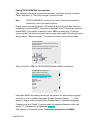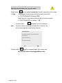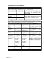
1
TECOTHERM NEO MEDICAL EQUIPMENT for Thermo-Regulation and Monitoring Instructions for Use Caution: Federal law restricts this device to sale by or on the order of a physician Revision November 2015 Applicable for software version 062/02.16 and higher Inspiration Healthcare Ltd Gildor House, West Street, Earl Shilton, Leicester, Leicestershire, LE9 7EJ, UK T +44 (0) 1455 840555 F +44 (0) 1455 841464 E [email protected] W www.inspiration-healthcare.com Page 1 of 60 Contents and abbreviations 1. 1.1 1.2 1.3 1.4 2. 3. 4. 5. 6. 6.1 7. 7.1 7.2 7.3 7.4 7.5 7.6 7.7 7.8 7.9 7.10 7.11 7.12 8 8.1 8.2 8.3 8.4 8.5 8.6 8.7 9 9.1 9.2 9.3 10 10.1 10.2 10.3 page Preface .............................................................................................. 4 Intended Use ............................................................................... ...... 4 Indications for Use………………………………………………………… 4 Contraindications for Use ................................................................... 4 Operators Profile ................................................................................ 4 Information for Customers, Service & Technical support .................... 5 Symbols, Indications ......................................................................... 6 Warnings & Precaution ………………………………………………....... 7 Safety & Reliability………………………………………………………… 8 TECOTHERM NEO Operating Function……………………………….. 10 Fallback mode……………………………………………………………… 10 TECOTHERM NEO Thermoregulation System………………………. 11 TECOTHERM NEO Operating Modes………………………………….. 11 TECOTHERM NEO System Information ............................................. 13 Modules and Main Components……………………………………………14 Alarm System and Monitoring Features…………………………………...16 Indicators and Operation Key elements, Display screen………………..17 TECOTHERM NEO Rear Face…………………………………………….18 Indicating Temperatures…………………………………………………….18 External Temperature Probes ............................................................. 20 Fill- up set for Filling/Refilling fluid…………………………...…………….21 Mattresses .......................................................................................... 22 MENU and the User Interface / USB connection ................................. 24 Treatment Data Selection and Transfer/USB Socket…………………….25 TECOTHERM NEO System Putting into operation .............................. 26 Initial Set up/Initial Operation............................................................... 26 Pre-operation Check up ...................................................................... 26 Initial Operation ................................................................................... 27 Stop operation/Turn off device ............................................................ 32 TECOTHERM NEO System: Filling/Refilling Procedures .................... 33 Draining a used mattress .................................................................... 35 Application of mattresses to patients ................................................... 35 Hygienic Requirements ....................................................................... 36 Cleaning and Disinfecting TECOTHERM NEO .................................... 36 Mattresses, thermally insulated hoses, tubing ........................................ 36 Temperature Probes ........................................................................... 36 Storage and Transport ........................................................................ 37 Storage of the TECOTHERM NEO device .......................................... 37 Storage of Mattresses ......................................................................... 37 Transport ............................................................................................ 37 Page 2 of 60 11 11.1 11.2 11.3 11.4 11.5 11.6 12 12.1 12.2 12.3 12.4 13 14 15 Alarm system, malfunctions, incident management…………….............38 System Alarm, System Failure ............................................................ 40 Temperature Alarm ............................................................................. 43 Flow rate alarm ................................................................................... 46 Alarm Fluid level low ......................................................................... 49 Alarm No Mains Power ...................................................................... 51 Fluid escapes from the TECOTHERM NEO System ........................... 53 Service, preventive maintenance, Software Update ............................. 54 Service & Maintenance ....................................................................... 54 Replacement of fluid in the device ....................................................... 54 Check/calibration of temperature probes ............................................. 55 Software Update ................................................................................. 55 Disposal .............................................................................................. 56 Technical Data, TECOTHERM NEO Specification .............................. 57 EMC guidance for TECOTHERM NEO ............................................... 58 Abbreviations IfU BCT SF Mattress Page 3 of 60 Instruction for Use Body Core Temperature, as measured via the Rectum or Esophagus using appropriate temperature probes System Failure Aqua Wrap/Mattress 1. Preface 1.1 Intended Use The Thermo-Regulation System TECOTHERM NEO is designed for controlled cold & heat treatment procedures. By means of a mattress, cold and heat is provided to the patient, depending on the therapy objective. The operator should be familiar with the operation modes and capabilities of the TECOTHERM NEO. Prior to use, carefully read this Instructions for Use (IfU). Note: The Manufacturer carries responsibility for basic safety, reliability and capability of the TECOTHERM NEO system only when local electrical installation fully meets the requirements of the IfU. operation is performed by authorized personnel. TECOTHERM NEO is operated according to the instructions and statements in this IfU. 1.2 Indications for Use The TECOTHERM NEO is a temperature management system for pediatric patients, indicated for controlling and monitoring patient’s temperature through conductive heat transfer. 1.3 Contraindications for Use No general contraindications are known. For possible adverse effects study the relevant treatment and therapy protocols. Avoid direct contact of mattress with fresh or non-closed wounds, infectious areas, areas with ulceration and abscesses, rash and burns. 1.4 Operators Profile TECOTHERM NEO is intended for use by healthcare professionals only. Operating a TECOTHERM NEO requires: Experience in using life support and life sustaining equipment Experience in using medical electrical equipment Operator must be trained in the use of the TECOTHERM NEO before operating the device. Note Operator should carefully check all set parameters for correctness before starting the treatment. Page 4 of 60 2 Information for Customers Service & Technical support For Technical Support please contact: Inspiration Healthcare Ltd Phone: +44 - 1455 840555 Fax: +44 - 1455 841464 E mail: [email protected] Inspiration Healthcare Limited or authorized representatives will instruct the operation personnel prior to putting the equipment into operation. Additional information, technical support, additional manuals may be requested from Inspiration Healthcare Limited and any authorized distribution partner. Authorized Distributor in the USA: Maxtec 2305 South 1070 West Salt Lake City Utah 84119 USA Phone: 385 549 8070 Fax: 801 943 6090 www.maxtec.com Manufactured for Inspiration Healthcare Limited by: TEC COM GmbH Am Krümmling 1, Eingang B, D-06184, Kabelsketal OT Zwintschöna, Germany Type label TECOTHERM NEO Serial Number 2013 / 07 / 01 100-130 / 200-240 VAC 50-60 Hz max. 350 VA Class: I IP20 Made in Germany Fuses: 5x20mm 250VAC 100-130V: S4AH / T4AH 200-240V: S2,5AH / T2,5AH Manufacturer: TEC COM GmbH, Am Krümmling Eingang B, D-06184 Kabelsketal OT Zwintschöna Germany 0494 Page 5 of 60 3. Symbols, Indications Important Information Attention, Caution, Warning Electrical Hazard ! Do not touch contacts! Applied Part Type BF Consult Instructions for Use BCT (Rectal) Temperature Sensor socket Skin Temperature Sensor socket Key “Turn On” System failure Temperature Alarm Alarm No or restricted Flow Alarm Low fluid level Symbol AUDIO paused No Mains Power (separate LED indicator) Internal System Failure (separate LED indicator) Page 6 of 60 4. Warnings & Precautions Warnings Do not modify the TECOTHERM NEO in any way. Do not open the device! Risk of electrical shock. Repair and maintenance are restricted to authorized personnel only! The TECOTHERM NEO device must be plugged to the mains using shockproof sockets. Mains voltage must be 100-130V or 200-240V with 50-60 Hz. Use only cord supplied with the device or a medical grade approved equivalent cord not longer than 2.5 m. Caution: During operation and treatment: The operator must not simultaneously touch the patient and metallic device parts (plug/connector sockets, fuse contacts, grounded connected parts at the device rear). Both temperature probe sockets on the front of the device and the USB socket on the rear are marked with ESD warning symbols. They are sensitive against discharge of static electricity, their electrical contacts should not be touched with the fingers or tooling. When connecting probes or USB stick to their sockets the following precautionary procedure is required: Before plugging, touch the fan protective grid at the rear with your other hand. For a reliable and safe operation use only original components, applied parts and spare parts supplied or recommended by Inspiration Healthcare Limited or the Authorized Representative. Only Sterile Water should be used as circulating fluid. Use only temperature probes in accordance with IfU and with the technical specification of the manufacturer. Applying different probes may lead to incorrect and wrong temperature data. This is likely to put patients at significant risk! Ensure that probes are properly connected to the TECOTHERM NEO socket marked "R" (for Body Core Temperature) and “S” (for Surface Temperature). Ensure that Rectal and Skin Temperature Probes are correctly placed in/on the patient and are properly secured. Do not use TECOTHERM NEO with, or in presence of flammable agents. Page 7 of 60 5. Safety & Reliability Warning: Substitution of original parts or components of the TECOTHERM NEO system by parts or components which are not licensed by Inspiration Healthcare Limited or the Authorized Representative is likely to put the system and the patient at risk! Precautions Notes: Therapeutic Induced Total Body cooling is a systemic treatment method. Select target temperatures cautiously. Re- warming: Select low re-warming rates to smoothly reach normal BCT of 37°C. Patient body mass may severely influence re-warming. The larger the mass, the slower the re-warming. Portable and mobile RF communication equipment can affect medical electrical equipment. Observe the recommended separation distances in the EMC tables. The TECOTHERM NEO device should be subject to regular maintenance and service. Refill sterile water regularly every 2 months, see section 8.5. Note: Circulation may stop, fluid flow stops. In such cases mattresses may cool patient down slowly. During treatment, (re- warming phase) patient may suffer from extraction of body heat back into the mattress. This must be addressed without delay. The operator or the user should not apply other cleaning, disinfecting and decontamination procedures than those recommended by the manufacturer. If in doubt contact your local representative. Precaution Notes for Placement Location The TECOTHERM NEO device should not be used adjacent to or stacked with other equipment. The unit must be placed in such a way that it could be easily disconnected from mains power. Removing the mains plug must always be possible. The unit must be placed horizontally onto a support. The system is fan cooled. Sufficient space must be allocated so that a free flow of air from all sides can reach the bottom of the device when it is in operation. Device should be located so that there is a distance of at least 15cm between rear face and a wall or another limiting surface to ensure free outflow of the cooling air. Do not place the device into small cabinet or onto small scale boards. Do not cover the device! The unit should be placed to avoid blowing air towards the patient. The unit should be placed so that visual alarms are clearly seen and acoustic alarms are clearly audible. Do not place mattresses and hoses onto hot or warm surfaces during operation. Do not operate the device near intensive heat sources. Page 8 of 60 Attention: Leave enough space around the TECOTHERM NEO so as not to obstruct passage of personnel. Ensure that hoses, cable cord, temperature probes etc. do not form obstacles. Ensure that placement of TECOTHERM NEO does not create hazards for hands and fingers, or any other injuries. Check mattress for visible damage. Note: Place mattress onto a 10-20 mm thick foam material that has good thermal insulation during operation. Using an incubator When using an incubator to perform treatment: Ensure there is enough space to properly place mattress. Otherwise kinking of tubing may occur. Place the hoses with as few bends as possible. Fasten the hoses in such a way to avoid kinking of the tubing near the mattress. Note: Place mattress onto a 10-20 mm thick foam material that has good thermal insulation during operation. Note: Do not put mattress directly onto compact silicon inlays used in incubators. Attention: Ensure that incubator heaters are shut off! Ensure that there is no forced air circulation. It may cool down the patient in a re-warming phase of the treatment. Indications for hazardous substances TECOTHERM NEO does not contain parts or substances originating from derivatives of blood or human/animal tissues. TECOTHERM NEO does not contain parts made of Latex or its derivatives. TECOTHERM NEO Applied Parts do not contain phthalates. Thermalizing Fluid is sterile water. Skin contact with sterile water is harmless. Ambient Conditions To ensure proper operation in normal use, pay attention to the following conditions Protection The device should be protected from dampness and wetness Do not operate device in rooms where flammable mixtures of anesthesia gases with oxygen, N2O or air may evolve. To have full cooling power, ambient temperature should not exceed 27°C. Otherwise the TECOTHERM NEO system may not achieve the lowest possible set temperature. Relative Humidity during treatment should be within a range of 30% - 80%. Ensure that during treatment/operation, no installations or devices are operating or are intended to operate next to TECOTHERM NEO which produce ultraviolet radiation, intense infrared radiation, strong electromagnetic radiation or mechanical shocks/vibrations. Page 9 of 60 6. TECOTHERM NEO Operating Function 6.1 Fallback mode If BCT measurements occur outside the range of acceptance, TECOTHERM NEO will stop operating as a physiologic closed-loop circuit and instead switch into fallback mode. Different criteria apply during treatment phases when the patient’s temperature is to be gradually adjusted at a pre-determined speed. It is known that in this case the mattress temperature will gradually change, at the same speed, albeit with a certain delay with regard to the pre-determined Body Core Temperature. In practice, however, the mattress temperature will not always need to be exactly 1° above the BCT and depending on the patient it may be even higher, as well as lower, than the BCT. User-Defined Treatment Profiles Within “Servo Control Complete Treatment Mode“ the user can set and store up to 9 (user-defined) Treatment Profiles. When changes are made to the default temperatures or times before the start of treatment, the user is given an option to save this new settings as a treatment profile. If selecting this option, the new settings will get the next free treatment profile number (1 to 9) for identification. If the starting point for the changes was a previously generated treatment profile, it can be redefined instead of creating another new treatment profile. After a treatment profile has been saved, there is a further option to store this profile as a future default. Once the user has created at least one treatment profile, when selecting the “Servo Control Complete Treatment Mode” in addition to the displayed temperatures and times corresponding to the profile declared as standard, the option to choose another profile will be offered. The process of creating a treatment profile can be canceled at any time. In any case, the treatment will always be performed using the settings that are shown on the display at the time of pressing the "Start" button. During treatment, temperature and time settings can be changed if necessary by pushing the "Options" button. However, these changes cannot be saved in profiles during the course of treatment. Page 10 of 60 7 TECOTHERM NEO Thermo-Regulation System Components and accessories: TECOTHERM NEO device Applied part (mattress) Temperature probe with connector Hose set, thermally shielded to connect application parts to the device Fill-up set, includes necessary components for filling/re- filling Electrical Power cord, up to 2,5 m Warning: Accessories specified for use with TECOTHERM NEO should not be used with other medical electrical equipment or systems. Optional accessories: Fluid Emptying Aid for mattress Storage boxes Chlorine Dioxide tablets for routine cleansing (available from device supplier) Treatment temperatures are strictly limited Body Core Temperature 32°C/38°C (lower limit/upper limit) in the treatment modes I and II Mattress temperature 12°C/39C Device internal temperature alarm limits: 10°C lower limit/41°C upper limit 7.1 TECOTHERM NEO operating modes Three treatment and operation modes of TECOTHERM NEO I Programmable Complete Treatment Mode (Servo controlled mode) II Servo Control Mode (constant rectal temperature) III Constant Mattress Temperature Mode Note: The operator can permanently follow the Body Core Temperature on the display screen. Treatment Mode I Programmable Complete Treatment Mode (Servo controlled mode) System is designed for cooling/heating and regulating the temperature of the patient. Treatment mode I allows selecting and setting target Body Core Temperatures within a range 32°C to 38°C. To start treatment follow and observe the instructions in the MENU. NOTE: All parameters can be changed from set position at ANY TIME should the need arise. Changes will be stored on the TECOTHERM NEO and can be seen on later analysis. In treatment mode I all temperatures/time dates are recorded/logged and can be read out/transferred to a USB stick, see section 7.13 for the USB port. Page 11 of 60 Treatment Mode II SERVO CONTROL Constant Rectal (BCT) Temperature Mode Target Body Core Temperatures 30° to 38°C. Each treatment section will result in the temperature being maintained until operator intervention. To start treatment follow the instructions of the MENU. Treatment section 1 Cooling-Down or Warming Phase Treatment section 2 Maintenance Phase NOTE: TECOTHERM NEO will not alarm the end of any section. The operator must observe whether the intended time of treatment has elapsed. Treatment Mode III NON-SERVO CONTROL Constant Mattress Temperature Mode When TECOTHERM NEO is run in the Constant Mattress Temperature Mode, to change body core temperature, an independent temperature measurement is required. Selectable mattress temperature range is 12°C to 39°C. In Treatment Mode III the operator is fully responsible for performing and selecting a treatment procedure. He has to select appropriate mattress temperatures and treatment times for cooling and re-warming. Attention Only the Mattress temperature is permanently displayed on the screen in the display feature (LARGE SIZE NUMBERS). Treatment Procedure Section 1 Cooling: Start treatment following the MENU instructions. Treatment section 2 Re- Warming NOTE: Patient body mass may severely influence the re-warming. The larger the mass the slower the re-warming. All temperatures/time dates are recorded/logged and can be read out/transferred to a USB stick, see section 7.13, USB port. Page 12 of 60 7.2 TECOTHERM NEO Thermo-Regulation and Monitoring system Information. For the TECOTHERM NEO no ESSENTIAL PERFORMANCES have been determined. TECOTHERM NEO is a light- weight, efficient and powerful Thermo-Regulation and Monitoring system Options Dimensions Mass / Weight Operation modes: Cooling/Warming, Normothermia 375 x 190/ 215 x 310 mm (W x L x H) 7,2 kg I Servo Control Complete treatment mode II Servo Control Constant Rectal Temperature III Constant Mattress Temperature Mattress temperatures for Total Body cooling / warming children up to 50 kg body mass +12°C to + 39°C Temperature constancy 0,3 °C Temperature accuracy 0,1 °C Body Core Temperature control range I 32°C.. 33,5°C..38°C II 30°C…. 38°C Hydraulic circulation system Fluid Reservoir capacity Fluid flow rate in operation Circulation System pressure Electrical power consumption sterile water approx. 250 ml up to 300ml/ min, with mattress up to 500 ml/ min short circuited max. 0,5 bar < 350 W (mains 100-130V / 200-240V 5060Hz) Applied Parts Rectal Probes TCM1837A single use. TC-D-RB2A reusable. Skin Probes TC-D-SO6-RGA reusable. Adaptor cable for disposable rectal probe TC989803162-601 reusable. Cool Wrap TC-MATT-NEO Material Dimensions Volume Mass (empty) Reusable, Manufacturer Inspiration Healthcare PUR polyurethane, transparent 620 x 420 mm 300 - 350 ml fluid 155 g Cool Wrap TC-MATT-DISP Material Dimensions Volume Mass (empty) Single Use, Manufacturer Inspiration Healthcare PUR polyurethane, coated 620 x 420 mm 300 - 350 ml fluid 220 g Page 13 of 60 7.3 Modules and Main Components Central Cooling / Warming Module Hydraulic Module for controlled circulation of fluid Micro Computer controlled Operating and Control Board, MENU, user interface Display for visualization of MENU operations and treatment / therapy scenario. Alarm and monitoring system Temperature probes Detailed software is implemented. Indicators and operation key elements/buttons are clearly arranged at the front panel. Mains socket and sockets for USB are positioned at the rear side. Figure TECOTHERM NEO Device Central Cooling/Warming module The Central Cooling/Warming module is a thermoelectric based unit which cools or warms the circulating fluid. This module is controlled and monitored by means of a microcomputer in the Control Board and supplied by a modern efficient switching power supply. It is fan cooled to remove heat produced by the Peltier elements. It is operating exactly to reach the target temperatures adjusted by the operator, and hold them constant according treatment protocol. Page 14 of 60 A large display serves as the user interface. MENU operations and treatment modes are visualized on the display screen. The operator either selects, confirms or modifies treatment modes, treatment options, operations and settings using MENU operation Arrow Keys to move to MENU entries. Pushbuttons below the display screen enable performing instructions like Select, Confirm, Cancel, Apply, Start etc. Currently selectable instructions and entries are highlighted turquoise. Display with MENU Arrow Cursor Arrow keys Page 15 of 60 7.4 Alarm System and Monitoring Features Alarm symbols shown on the display are indicating system errors and failures System failure. SF Temperature Alarm. Alarm No or restricted flow Low fluid level Audible alarm, paused TECOTHERM NEO is equipped with detailed alarm and monitoring elements. Main purpose is monitoring and detection of temperatures and flow of the circulating fluid, of internal temperatures in the Central Cooling/Warming module, of the temperature limits, mains power failure. When detecting deviations from the limits and/or failures the alarm system initiates optical and audible alarms, and the above shown indicators appear on the screen. Details on indicators see section 7.5. SF Mains Power failure and certain internal system failures are indicated by LED indicators in the lower front panel, just below the display screen. For details see section 11 Alarm System. Mains Cable Cord TECOTHERM NEO is powered via a medical grade cord to a shock-proofed mains socket with 100-130V or 200-240V and 50-60Hz. Cord should be up t o 2.5 m long and approved for shock proofed sockets only. Page 16 of 60 7.5 Indicators and Operation Keys, Display screen Figure TECOTHERM NEO front panel view (1) Pushbutton to power the device on, marked ”I“ (S) Temperature Probe Socket Skin Probe (R) Temperature Probe Socket Rectal (Body Core Temperature) Probe (4) LED Indicator Mains Failure (5) LED Indicator System Failure “SF” (T 1) Pushbutton for MENU operations, meaning indicated on display (T 2) Pushbutton for MENU operations, meaning indicated on display (T 3) Pushbutton for MENU operations, meaning indicated on display (T 4) Pushbutton Arrow Key: menu upwards or increase value (T 5) Pushbutton Pausing Audible Alarm (T 6) Pushbutton Arrow Key: menu downwards or decrease value (6) Female Coupling / socket for connecting hoses or mattresses (7) Female Coupling / socket for connecting fill- up set Page 17 of 60 7.6 TECOTHERM NEO Rear Face (8) Mains Socket (9) USB socket 7.7 Indicating Temperatures Running the 3 main treatment modes, treatment temperature is shown on the screen in a large size (display feature LARGE SIZE NUMBERS). Rectal temperature is displayed when selecting treatment mode I or II. temperature is shown when selecting treatment mode III. Mattress Treatment modes I and II As long as measured temperature deviates more than 0.5 °C from the Set Point the temperature is appearing RED. So, for example, if Set Point is 33.5°C a measured temperature of 36.4°C is displayed RED. Only when deviation is < 0.5°C color changes to GREEN. Page 18 of 60 36.4 33.4 Set Point 33.5 Set Point 33.5 Treatment mode III As long as measured Mattress Temperature deviates more than 0.5 °C from the Set Point the mattress temperature is appearing RED. So for example if Set Point is 30.0°C a measured temperature of 34.1 °C is displayed RED. Only when deviation is < 0.5°C color changes from RED to BLUE. 34.1 30.2 Set Point 30.0 Set Point 30.0 60 seconds after starting treatment in each of the main treatment modes the display feature DIAGRAM is changed to the feature LARGE SIZE NUMBERS. Here shown for treatment mode II Servo Control Constant rectal temperature. 23.03.2010 35 35 30 30 25 25 20 20 15 15 1 Page 19 of 60 33.6 hour Set Point 33.5 7.8 External Temperature Probes Patient Temperatures should be measured using approved calibrated Temperature probes. TECOTHERM NEO applies a Rectal Temperature probe and a Skin temperature probe: Reusable Rectal Probes (pediatric) Type TC-D-RB2A, autoclavable Single-Use Rectal Probe Adaptor Cable for TCM1837A Type TCM1837A TC989803162-601 Reusable Skin Probe (pediatric) Type TC-D-S06-RGA, with REDEL connector, autoclavable. NOTE Rectal probe and Skin probe connectors have their individually mating sockets R and S! Ensure correct connections! Body core temperature BCT is measured with the rectal probe. Ensure that the probe is correctly inserted in the patient and that it is properly secured. Also ensure that the probe is properly connected to the TECOTHERM NEO socket marked R ! The second temperature probe (reference probe) is plugged to the TECOTHERM NEO socket S . It independently monitors a second patient temperature. Figure Page 20 of 60 TECOTHERM NEO with Temperature Probes 7.9 Fill-up Set for Filling/Refilling Sterile Water Fill-up set is a 500 ml fluid container made of HD polyethylene or of polypropylene material, marked every 50ml. The cap has two connecting adapters made of polyurethane tubing equipped with male QDC couplings. To fill–up/refill TECOTHERM NEO device, male connectors are plugged into ports (7) in the device front panel, section 7.3. Figure Fill- up set Female connectors Page 21 of 60 Non- Return Valve 7.10 Mattress (pictured on following page) For transfer of cold and heat to a patient within total body treatment, disposable wrap mattresses are used. All have connector parts connecting them to the hoses, limited to working pressure 0.5 bar. The working pressure is limited to 0.5 bar. For positioning the mattress, use the felt fixation tapes. Tapes are fed through eyelets at right and left sides of the wrap then forming a loop. Both tape ends are knotted. The operator may select by choosing the appropriate loop length to what extent the patient is wrapped. Page 22 of 60 620 mm Page 23 of 60 7.11 MENU and the User Interface/USB connection TECOTHERM NEO provides a comfortable Man-Machine Interface: MENU as the User Interface, display screen as Visual Interface and Pushbuttons/Keys to move along the MENU instruction entries. Display visualizes MENU operations and treatment procedures The operator either selects, confirms or modifies treatment modes, treatment options, operations and parameter settings using the Arrow Keys to move to MENU entries. Such active entry is colored turquoise. Direction of movement corresponds to the arrow keys., Pushbuttons below the display screen enable instructions like Select, Confirm, Cancel, Apply, Start etc. TECOTHERM NEO Main MENU always serves as a Starting point for navigation. Using Main MENU the operator selects a Menu language: entry Language, see section 8.3. Entries at the MENU left side are accessible for the operator except entry SERVICE. Access to entry SERVICE is only for service personnel using a password. TECOTHERM NEO Main Menu Highlight and Select Function Required: Servo controlled complete treatment mode Servo control mode (constant rectal temperature) Constant Mattress Temperature Mode Alarm check Export treatment data Service Language Power Off Ser.-Nr. 2010/08/01 Rev. 023/01.32 Select Alarms and errors are indicated optically by ICON symbols SF Page 24 of 60 Important entries, instructions, notes and failures are displayed as turquoisehighlighted Pop- Up Windows TECOTHERM NEO A check of the internal functions has been performed and did not detect any malfunction. Now the alarm functions will be checked. Can you see the various Symbols and clearly hear the two alarm sounds? ERROR It is not allowed to run the device without working alarm functions. It will shut off in 30 seconds (press "Confirm" to shut off immediately). No Yes Important conditions and preconditions to perform treatments are displayed on the screen. The operator has to Confirm or Cancel. Servo controlled complete treatment mode NOTE: A rectal probe is required to be inserted prior to treatment. Please ensure its correct placement prior to starting treatment. For reference, an additional skin temperature probe is strongly recommended. Please confirm the requirement for a rectal probe by pressing the "Confirm" button! 7.12 Treatment Data Selection and Transfer/USB socket To read out and export treatment data and data log files select Entry Export Treatment Data in the Main MENU. To perform export, plug a USB stick into the USB port (9) at the rear side of the device. Then follow MENU instructions. The operator gets an indication on the screen whether data export was successful. After successful export, unplug USB stick. Page 25 of 60 8 TECOTHERM NEO System Putting into Operation 8.1 Initial Set Up/Initial Operation The manufacturer or authorized service personnel should initially set up the TECOTHERM NEO system. The operators should be trained how to run the system. 8.2 Pre-operation Check Caution Ensure that power cord matches the shockproof socket at site (100-130V or 200-240V, 50-60Hz). Caution Ensure that correct temperature probes have been prepared and prepositioned. Caution Ensure mattress has been prepared and prepositioned. Prior to putting the system into operation, check the conditions of section 5 to ensure safe and proper operation: Warning: For a reliable and safe operation use only original components and applied parts (mattress) supplied by the manufacturer. Otherwise proper and safe operation cannot be guaranteed. Check that only sterile water is used as circulating fluid. Check mattress for visible damage. Check whether the correct temperature probe is prepared. Its connector must match the socket “R” at the device front panel. Without rectal temperature probe plugged to port “R” it is not possible to start treatment modes I and II. If all of these preconditions are fulfilled, the device can be put into operation. Page 26 of 60 8.3 Initial Operation If mattress is positioned in an incubator read notes in section 5. Plug the cable cord into rear socket (8). Then plug the system to the mains into shockproofed socket. Fuse data see section 13, Technical Data, and type label. Note: Immediately after plugging to mains TECOTHERM NEO is in its Standby mode. Key (1) is lit green. Next Step: Connect mattress to the TECOTHERM NEO Prior to connecting check whether mattress is filled completely. If empty or only partially filled, see section 8.5 for filling instructions. defects like punctures and flaws are possible. If fluid escapes replace defective mattress. tubing is kinked or likely to kink. Connect QDC couplings of hoses to the QDC counterparts of the mattress. Then plug to the ports at the device right lower front part, see figure. If they do not engage properly, push metallic unlocking keys at the QDC, then repeat plug procedure. Figure Connection to ports Unlocking Keys Note: To unlock push metallic unlocking keys downwards. Place completely filled mattress onto a 10-20 mm thick plastic-foam material that has good thermal insulation, e.g. in a prepared incubator. Page 27 of 60 Connecting Temperature Probes to TECOTHERM NEO device NOTE: For treatment modes I and II a rectal probe is required. NOTE: Ensure that only correct probes are used. Patient temperature measurement must be accomplished only with probes approved by Inspiration Healthcare Limited or the Authorized Representative. Only these have been tested as required and ensure a sufficiently accurate and reliable temperature measurement even in an unfavorable electromagnetic environment. Using other temperature probes could put the patient at risk! Reusable Rectal Probes (pediatric) Rectal Probes (pediatric) Type TC-D-RB2A, autoclavable Single-Use Rectal Probe Adaptor Cable for use with TCM1837A TCM1837A TC989803162-601 Reusable Skin Probe (pediatric) Type TC-D-S06-RGA, with REDEL connector autoclavable. NOTE: Rectal probe and Skin probe connectors have their individually mating sockets R and S ! NOTE: Not all accessories will be available in all markets due to regulatory compliance If patient is prepared for treatment: Ensure that the rectal probe is correctly plugged to its socket “R”. Probe must be correctly inserted in the patient and properly secured. If a skin probe is used plug it correctly to its socket “S”. Place it correctly at the abdomen or at the forehead and secure it. Page 28 of 60 Putting TECOTHERM NEO into operation After completing the above mentioned preparations the system is ready to operate: Press Pushbutton (1). The lit key changes to intensive Green. Note TECOTHERM NEO is running a self- test to check internal functions followed by a test of the alarm functions. Display screen must be illuminated, LED indicators (4) and (5) must flash. Device is emanating an intensive BEEP, followed by a blue flash of the T5 button and intensive double BEEP. The operator is asked to confirm YES by pressing key T3, that the various symbols can be seen and two alarm sounds clearly heard. Should anything be wrong, answer NO pressing key T1 or simply do nothing. Device will shut down. TECOTHERM NEO A check of the internal functions has been performed and did not detect any malfunction. Now the alarm functions will be checked. Can you see the various Symbols and clearly hear the two alarm sounds? SF After confirmation YES the TECOTHERM NEO Main MENU is displayed. TECOTHERM NEO Main Menu Highlight and Select Function Required: Servo controlled complete treatment mode Servo control mode (constant rectal temperature) Constant Mattress TemperatureMode Alarmcheck Export treatment data Service Language Power Off Ser.-Nr. 2010/08/01 Rev. 023/01.32 Select Using Main MENU and pushing arrow keys the operator can select entry Language and is led to a list of available languages (English, Deutsch, Espanol, ….. ). After selection, display screen promptly shows the Main Menu in the selected language. Pushing arrow keys T4 and T6 you may select the operation/treatment mode, see section 7.1. Selected entry is highlighted turquoise. After selection of a treatment mode: Follow the Instructions in the MENU. Page 29 of 60 Adjustment of treatment parameters, treatment start In main menu, select one of the treatment modes, details see section 7.1: I Programmable Complete Treatment Mode (Servo controlled mode) II Servo Control Mode (constant rectal (BCT) temperature) III Constant Mattress Temperature Mode All treatment modes are specified by their respective menus. Note: Pay attention to the entries highlighted turquoise. Entry instructions are requesting adjustment to treatment temperatures and times/durations pushing the arrow keys once or repeatedly. Having selected treatment mode and accepted default values or modified the relevant treatment parameters, and having positioned the patient on the mattress, press Start button. Treatment begins. In treatment modes I and II, the measured rectal (BCT) temperature must be within 29°C to 39°C. Otherwise, Start will be denied because rectal (BCT) temperatures outside this range are regarded to be unacceptable (measured incorrectly). Treatment is started TECOTHERM NEO is programmed to reach target temperature as soon as possible if no other rate input is chosen by the operator (time to reach final temperature > 0 h). The operator may observe the temperature – time profile in the display feature DIAGRAM and actual temperature values in the small parameter boxes in the upper part. Independent of treatment mode, feature DIAGRAM changes after 60 seconds automatically to feature LARGE SIZE NUMBERS. Page 30 of 60 Treatment is running Treatment is running according to, and depending on, selected treatment mode and applied treatment parameters. All treatment data like temperatures/time dates are automatically recorded/logged and can be read out/transferred to a USB stick. During treatment, the operator should, from time to time, monitor patient temperatures. This is especially important during transition from cooling (section 3) to re warming (section 4). NOTE: All parameters can be changed from set positions by pushing key T3 Options and selecting entry Change the current settings, see below. Pushing T1 (Back) returns the system to its original settings. Options during operation The current operation continues to run. Highlight and select the desired option: Changes the current settings Immediately start the re-warming phase End treatment and save data Alarmcheck Back Select End treatment When treatment approaches the end, the operator may continue with a treatment. Otherwise following the MENU instructions he is requested to select the instruction End Treatment and save data using the arrow keys. Final temperature is currently unchanged Highlight and select the desired option: End treatment and save data Back Select Doing so returns to the main menu. From there, another treatment can be started, export stored treatment data or turn off the device. Page 31 of 60 Display and export of treatment data To read out and export treatment data and data log files select Entry Review and export of treatment data in the Main MENU. This submenu offers 3 options: Export new treatment data Export all treatment data Select, review and export particular treatment data. Here, "new treatment data" means all those treatments which never have been exported so far, including in any case a possibly just only finished treatment. Option "Select, review and export particular treatment data" provides a comfortable possibility to graphically represent the complete progress of an earlier treatment identified by date and time at which it has been started. If necessary, this data can then be copied to a USB stick. To find a specific patient record, the user must first select the year of the treatment, then the month, the day and finally the specific treatment itself. Should there be more entries than available lines, the list automatically scrolls when the last (or the first) line is reached. The function can also be used to simply display the graphics, without actually exporting the data at the end. To perform export plug an USB stick into the USB port (9) at the rear side of the device. Then follow MENU instructions. The operator gets a message on the screen notifying the user whether or not data export was successful. After successful export unplug USB stick. 8.4 Stop operation / Turn off device To stop or to interrupt operation turn back to the TECOTHERM NEO Main MENU. Then push Arrow Key ▼ to move to entry Power off and finally push button “Select”. Page 32 of 60 TECOTHERM NEO Main Menu Highlight and Select Function Required: Servo controlled complete treatment mode Servo control mode (constant rectal temperature) Constant Mattress TemperatureMode Alarmcheck Export treatment data Service Language Power Off Ser.-Nr. 2010/08/01 Rev. 023/01.32 Select After a few seconds device is shut off. NOTE Push button (1) is lit (but dimmed) as long as system is plugged to mains. Only unplugging the mains will cause green push button light to turn off. Disconnection from mains: Unplug the cable cord from the mains shock-proofed socket or from the rear socket (8). 8.5 TECOTHERM NEO system: Filling/Refilling Procedures TECOTHERM NEO’s hydraulic module is equipped with an internal fluid tank of 250 ml volume containing circulating fluid. This container is prepared and prefilled by the manufacturer ready for operation. To ensure a safe operation and a proper fluid circulation prior to each treatment fill/refill device and mattress properly and correctly. Attention: Do not use a partially filled mattress in hypothermia treatment. Procedures: Preparation of fresh mattress: Check mattress for defects and damage. Place mattress horizontally spread onto a plane support (table). Connect QDC couplings of hoses to the mattress QDC counterparts. Then plug to the ports (6) at the device right lower front part, see section 8.3 of this IfU. Preparation of fill-up set, see also section 7.9 of this IfU. Check fill-up set for defects, damages & leaks. Fill-up fluid bottle with sterile water up to the mark 450 ml. After filling close bottle cap tightly. Filling/Refilling Connect QDCs of the fill-up bottle to the refill port QDC counterparts (7) at the device front face. Put TECOTHERM NEO device into operation, see section 8 of this IfU. In Main MENU, select desired Treatment Mode and start operation. Page 33 of 60 Now lift fill-up bottle and turn it until cap is directed downwards. Attention: If Flow rate alarm appears ignore it or push key T5 to silence audible alarm (AUDIO paused, appears at the display.) Fill up until air bubbles inside the fill-up bottle disappear. Then disconnect bottle QDC from ports (7) To remove residual air bubbles in the mattress via mattress tubing outlet, move and swing mattress slightly after filling operation. Re-fill the fluid bottle with sterile water and connect it again as described above. Continue filling up until air bubbles inside the fill-up bottle disappear again. If audible alarm is active silence it by pushing blue button T5. Close open Pop-Up window if activated. Continue TECOTHERM NEO operation for 1 min. If within this time period alarm “No Flow” appears or reappears, follow the instructions in the display Pop-Up window.. End procedure as described above. TECOTHERM NEO system is ready to start the intended treatment. Refilling TECOTHERM NEO device during treatment TECOTHERM NEO device is put into operation, mattress is correctly connected and treatment is properly running. During treatment symbol Low liquid level appears. Low fluid level may be caused by loss of sterile water. Lack of fluid or low fluid level is indicated by the symbol appearing at the screen accompanied by an audible alarm. Button T5 is lit blue. A refill/top-up of fluid is required. Proceed as follows 1. Push key T5 to silence audible alarm. AUDIO paused, appears at the display. 2. If not prepared fill the fill-up fluid bottle with sterile water up to the upper mark 450 ml. After filling close bottle cap tightly. 3. Turn bottle until cap is directed downwards and keep in this orientation until the whole fill-up procedure is finished. 4. Connect QDC of the fill-up bottle to the refill port QDC counterparts (7) at the device front face. C h eck connection of QDCs of the fill-up bottle to the ports of QDC counterparts. Attention: If alarm No Flow appears ignore it or push button T5 again. 5. Refill until symbol disappears, continue filling until rising air bubbles in the bottle disappear. 6. Disconnect QDC connectors of the fill-up bottle from the device. If alarm Low fluid level reappears repeat refilling procedure as described. Page 34 of 60 Attention: Frequent or permanent appearance of the alarm indicates a malfunction or system failure. Please, follow sections 11.4 and 11.6. Replacement of Sterile Water see section 13.3 8.6 Draining a used mattress First drain fluid from the inner container; Disconnect hoses Connect the empty Re-fill bottle instead, with cap upwards Start mattress mode and wait until all liquid is in the bottle Ignore (or mute) any flow alarm or fluid level alarm Disconnect bottle, discard fluid and connect again as described Now drain fluid from the mattress 8.7. Connect mattress to the refill port couplings (7) at the device front face, turn mattress upwards Wait for about 1 minute until all the liquid is drained from the right half of the mattress Disconnect mattress and re-connect with connectors swapped, turn mattress upwards Wait for about 1 minute until all the liquid is drained from the mattress Disconnect mattress Disconnect Re-fill bottle, discard fluid. Application of mattresses to patients Dimensions: Mattress TC-MATT-DISP/TC-MATT-NEO Attention: 440 x 620mm Do not kink hose set and tubing! Do not fold mattress! Kinking and folding will stop fluid circulation and hence cooling or warming operation of the TECOTHERM NEO system. Alarm No Flow may appear. For further details see section 11.3. Before applying to human body pay attention to the following items Use only mattresses specified by the manufacturer. Mattresses must not be touched with sharp or tipped objects due to risk of puncture damage. Liquid may escape! Attention: Page 35 of 60 Avoid direct contact of mattress with non-closed wounds, infectious areas, areas with ulceration and abscesses, rash and burns. Application Place mattress horizontally spread onto a plain support. Ensure that mattress and ports (6) are on the same level, approximately. Place mattress onto a 10-20 mm thick thermally insulating layer for ensuring good thermal insulation during treatment. 9. Hygienic Requirements 9.1. Cleaning and Disinfecting TECOTHERM NEO Attention: Prior to cleaning and disinfecting, switch off system and unplug from mains! The external cleaning and disinfecting of the device including hoses should be performed using a damp sponge or cloth soaked with a liquid disinfectant, or a spray disinfectant in combination with a dry cloth. Clean and disinfect device bottom side (ventilation holes) once every 1-2 months and just before treatment as a part of the system preparation. Inspect once every three months that air ventilation holes in the device bottom are not covered and are free from dust. Remove fluff and dust using a small vacuum cleaner. 9.2 Mattresses, thermally insulated hoses, tubing Used Disposable Mattresses must be discarded as hazardous waste. Attention: Do not sterilize Reusable Mattresses. Attention: When the mattress has been in contact with blood or human secretion, during treatment, it must be replaced. Attention: Reusable mattresses should only be used in combination with thin fabric protective interlayer with plastic coating at bottom side. Interlayers are TECOTHERM NEO accessories and can be supplied by the distributors or the manufacturer. Such protective interlayer is disposable single-use product. 9.3 Temperature Probes Reusable Temperature Probes must be disinfected and sterilized after treatment as usual in clinical practice. For details read IfU of the manufacturer of the probes. Caution: Keep cable connectors dry to ensure proper probe and device operation! Do not dip them into liquids! Page 36 of 60 10. Storage and Transport 10.1 Storage of the TECOTHERM NEO Device Device: The TECOTHERM NEO should be stored in a closed cabinet to protect it against mechanical damage and dust. Put it onto a solid surface horizontally standing on feet. Store in dry ambient conditions. Mains cable: Keep cable near by the device. Put it into a separate plastic storage bag. Close bag. Fill- up Set: The empty set is supplied in a box or bag. Put filled or partially filled set into the set box, beside the basic unit. Keep cap tightly closed to avoid leakage of coolant fluid. Protect QDC couplings against mechanical damage. Store in dry ambient conditions. Hoses: Hoses are supplied in a closed airtight plastic envelope or a closed box. Keep it closed until preparing TECOTHERM NEO for operation. After use, disinfect hoses and put them back into the box or the plastic envelope. Keep hoses near the device. 10.2 Storage of mattresses Unused mattresses should be stored in the original box or package. Store in a dry and dark environment. Storage time for empty fresh mattresses in the closed storage box or envelope should be no more than 3 years. 10.3 Transport TECOTHERM NEO is a light- weight system with weight 7,2 kg when the fluid reservoir is full. Carry it to move the device over short distances or use an appropriate trolley. When carrying do not touch or damage display screen. Page 37 of 60 11. Alarm system, malfunctions, incident management Five (5) alarm functions are activated during operations to indicate any malfunction of the system. Alarms during operations are indicated by an acoustic signal, and a corresponding symbol o n the display. The push-button T5 will light up at the same time and may be used to switch the acoustic alarm to mute, for a period of eight (8) minutes. Alarm functions are all of medium priority. No patient-assigned alarms exist. The alarm “No mains power/No system voltage” has a sound level of dB(A) 63 approximately, the other alarms of dB(A) 57, approximately. Interruption of power supply does not influence or alter the alarm settings. They are automatically restored when power is on and alarm cause persists. Assignment of alarm functions to failures and conditions: SF System alarm - Internal system failure. Temperature alarm - System operation temperature deviation of more than 0,5°C from set temperature. No flow- No or very restricted circulation of the fluid. Fluid level low- Fluid deficit in the internal fluid container. AUDIO paused. No mains power- No system voltage due to mains power failure. Alarm No Mains Power appears when device operation is stopped due to lack of electrical power. Hence this kind of alarm cannot be displayed at the display screen. This failure is indicated optically by a separate LED lit indicator (4) at the device lower front side, see section 7.3, and by a separate intensive audible alarm. This alarm can be silenced finally pushing key T5 AUDIO paused. Page 38 of 60 NOTE Whenever an alarm appears, first push key T5 to silence audible alarm (AUDIO paused, appearing at the display.) is After Switch On of the TECOTHERM NEO the operational readiness of the alarm system is automatically checked through self-testing. Display screen is showing the Information TECOTHERM NEO A check of the internal functions has been performed and did not detect any malfunction. Now the alarm functions will be checked. Can you see the various Symbols and clearly hear the two alarm sounds? SF Confirm YES when you see the various symbols and clearly hear the two alarm sounds. If not press NO. The display then shows a Pop Up window ERROR. It is not allowed to run the device without working alarm functions. TECOTHERM NEO will shut off at after 30 seconds. TECOTHERM NEO A check of the internal functions has been performed and did not detect any malfunction. Now the alarm functions will be checked. Can you see the various Symbols and clearly hear the two alarm sounds? ERROR It is not allowed to run the device without working alarm functions. It will shut off in 30 seconds (press "Confirm" to shut off immediately). No Yes Push key T3 Confirm to immediately shut off device! Page 39 of 60 Operator can check alarm functionality at any time during treatment using MENU. First push key T3 Options and then use arrow keys to highlight this function. Options during operation The current operation continues to run. Highlight and select the desired option: Changes the current settings Immediately start the re-warming phase End treatment and save data Alarmcheck Back Select In critical cases, a detailed text display with instructions will appear. This text field will give information concerning the nature of the fault, as well as providing instructions as to what measures need to be taken to eliminate the problem. This text field will not disappear automatically, even though the AUDIO alarm might have been silenced. It must be closed using push button T3, this allows sufficient time for the information to be read and understood by the operator. 11.1 System Alarm, System failure SF System Alarm is caused by a serious internal failure. Two (2) SF alarm features are used: 1 2 Caution Symbol is displayed at the screen, display feature DIAGRAM, accompanied by acoustic alarm. System alarm SF LED (5) in the lower part of the front panel. The LED pictogram is activated accompanied by acoustic alarm. System failures will not be reset automatically, Device cannot be used in this error state. Page 40 of 60 We draw your attention to a very rare event System alarm 1. Step SF can be released accidently. Symbol is appearing at the screen. Unplug mains connector from the device socket at rear side TECOTHERM NEO is switched OFF. Wait 5 seconds. Plug mains connector back to the device socket TECOTHERM NEO is switched If System alarm Note: SF ON. disappears continue treatment. Previous treatment continues normally after confirming Yes at the screen appearing when power returned: TECOTHERM NEO Power failure during treatment - do you wish to continue with previous treatment? Confirm to continue with "Yes" or Start a new treatment with "No". If System alarm SF remains or appears again after a short time Shut off device by unplugging Mains cable Page 41 of 60 SF Symbol System Alarm is displayed at the screen. Caused by Failure in the TECOTHERM NEO system - Defective Central Cooling Module - Defective pump - Temperature exceeding internal limits - Communication problems between Operational System and Control system Measures Step1 has been carried out, but did not solve the problem: Shut off device by unplugging Mains cable Or NOTE: Push key T3 Options, end treatment and return to the Main MENU. Pushing key T6 select Power Off and turn off device. Device cannot be turned back on. TECOTHERM NEO Main Menu Highlight and Select Function Required: Servo controlled complete treatment mode Servo control mode (constant rectal temperature) Constant Mattress TemperatureMode Alarmcheck Export treatment data Service Language Power Off Ser.-Nr. 2010/08/01 Rev. 023/01.32 Select Device cannot be used. Contact your local service provider, for assistance. If possible, replace TECOTHERM NEO device with a spare unit. Put it into operation according to IfU. SF System Alarm SF Alarm feature 2 LED (5) in the lower part of the front panel is activated. In case a serious communication error between Operational Board and subordinated Control Board, after 10 seconds the Control Board creates an acoustic alarm, and SF LED (5) is lit. System continues operating with the set parameters unless operator silences audible alarm pushing key T5 AUDIO paused. Then, another 10 seconds later the Control Board will switch off the device. The operator can now analyze the situation and make an attempt to restore device operation by turning it ON again. In any case subsequently contact your service partner. Page 42 of 60 11.2 Temperature alarm Temperature alarm The display changes from Temperature indication LARGE NUMBER to DIAGRAM feature indicating the alarm symbol. Audible alarm also appears. Servo controlled complete treatment mode Servo controlled complete treatment mode 32.7 33.5 Mattress Temperature SetTemperature RectalTemperature 32.7 Skin Temperature Elapsed time of cooling phase 02:34 of 72 hours 36.8 ----08:55:42 25 15 Set Point 33.5 Current Measured Temperature Temperature alarm, alarm paused Caused by Temperature probe disconnected from the device or sensor break Temperature probe is detached from patient System operation temperature deviates more than 0,5°C from set temperature. Mattress temperature incorrectly measured Fan cooling insufficient Power of Central Cooling Module insufficient. NOTE When alarm appears push key T5 to silence audible alarm (AUDIO paused, appears at the display) There are now 8 minutes to resolve the problem. Elimination/ Management Attention: Check immediately whether Temperature probe is correctly connected to the device and the patient. The operator should check and analyze the temperature profiles in the DIAGRAM feature. Look first at the temperatures in the upper part of the display and check whether indicated temperatures are corresponding to the treatment section temperature settings and are plausible and make sense. Page 43 of 60 In all following cases 1 – 5: If possible replace TECOTHERM NEO device by a replacement unit or a spare unit. Put new system into operation following IfU. Case 1 There is no indication of patient temperature, in the -----DIAGRAM feature Device immediately switches to FALLBACK MODE, and a decision on the future progression of the mattress temperature is required. Measure Check whether Temperature Probe is plugged correctly to the socket R. If not, rectify. If cause is eliminated, rectal temperature reappears in the information box. Observe display until measured temperature approaches the set temperature. If no success, probe may have a sensor break or is electrically short circuited. In this event, replace probe with a prescribed temperature probe correctly in the rectum of the patient, secure it. Plug the probe into socket R. Observe temperature indicator at the display. If still no temperature indication appears repeat procedure with another new probe. If this still fails, turn off the device, see section 8.4. Contact and inform your local service. Case 2 All temperatures are indicated. Measured temperature deviates more than 0,5°C from the set temperature. Note In treatment sections 2 Cooling phase and 3 Re-warming phase a maximum deviation of +/- 0,5°C is allowed (alarm limit). Example Indicated rectal temperature is lower than set temperature 33.5°C. Measure Check whether rectal probe is placed in its correct position or slipped out completely or partially. The more it is slipped out the lower the detected and indicated temperature (approaching ambient temperature). If slipped out place probe into correct position and secure it. Example Indicated rectal temperature is higher than set temperature 33,5°C. Measure Cooling capacity of the device may be reduced. System is fan cooled. Possibly, free flow of air is restricted. Check whether device is placed onto a soft layer or pillow etc, which restricts free flow of air from the bottom of the unit. If so place device onto a plain solid support. Check whether distances to surrounding walls are at least 15 cm. Page 44 of 60 30,5 34,5 Case 3 Check Mattress temperature indication If mattress temperature is not indicated in the DIAGRAM feature, the Control board cannot regulate to hold rectal temperature constant. Measure Push key T3 Options, stop treatment. In Main MENU select entry Power Off using arrow keys and then push T3 Select. Device is shut down. Do not switch on the device again! Contact your local service provider. Case 4 Check ambient conditions Check whether ambient temperature is too high exceeding 27°C. This can be caused by an external heat or infra-red radiation source, within or near the incubator. Remove causes as appropriate. Observe rectal temperature. It should reach the set temperature after some time. If measured rectal temperature continues to deviate from the set temperature the device is defective. Push key T3 Options, stop treatment. In Main MENU select entry Power Off using arrow keys and then push T3 Select. Device is shut down. Do not switch on the device again! Contact your local service provider. If possible replace TECOTHERM NEO device by a replacement unit or a spare unit. Put new system into operation following IfU. Case 5 External heat sources below mattress Check whether a warming mattress (like electrically heated mattresses in incubators) is placed below the mattress. Remove as appropriate. Observe rectal temperature. It should reach the set temperature after some time. If measured rectal temperature continues to deviate from the set temperature the device is defective. Push key T3 Options, stop treatment. In Main MENU select entry Power Off using arrow keys and then push T3 Select. Device is shut down. Do not switch on the device again! Contact your local service provider. If possible replace TECOTHERM NEO device by a replacement unit or a spare unit. Put new system into operation following IfU. Page 45 of 60 11.3 Flow rate alarm Flow rate alarm: Insufficient circulation of cooling fluid. Maintenance of the treatment temperature is no longer guaranteed. An acoustic alarm will sound and a Pop-Up window will inform the operator what actions need to be taken in order to restore normal circulation. Example: Constant Mattress TemperatureMode Set Temperature Rectal Temperature 28.0 Mattress Temperature 34.2 SkinTemperature 28.2 ----- Constant mattress temperature for 00:43 hours 23.08.2011 08:55:42 ERROR 35 30 25 35 The total flow is very low. Check connectors. Check hoses, tubing and mattress for kinking. If nothing is found top up the system with fluid. Connect the right fill-up set connector to the right refill port. Fill up with 100 ml fluid, then disconnect. 30 25 20 20 15 15 90 74 58 42 26 10 6 4 2 1 hour Close Options Caution: We recommend to first pause the acoustic alarm by pressing the lit up push button T5. Please study the instructions for the correction of errors carefully and then close the text display window. The diagram will reappear and the icons will remind you that although the acoustic alarm has been switched to mute the error still remains: Constant Mattress TemperatureMode 28.0 Mattress Temperature Set Temperature Rectal Temperature 34.2 Skin Temperature Constant mattress temperature for 00:43 hours 28.2 ----- 08:55:42 35 35 30 30 25 25 15 20 20 15 90 74 58 42 26 10 1 hour Options The alarm will be muted for 8 minutes, following which the acoustic alarm will be activated again. Although the acoustic alarm can be switched again to mute, the problem remains and needs to be resolved. As long as this state of alarm does exist the unit is no longer able to regulate the patient’s temperature in the required manner! Page 46 of 60 No or very limited circulation/flow of the fluid Alarm indicates that for more than 10 seconds mattress gets too little fluid, or flow is very low due to blockage, or there is too little fluid in the mattress. Possible causes may be 1 Pump is not working or with insufficient power 2 Kinking of hose set and/or tubing near mattress; mattress folded; couplings disconnected. 3 Flow blocked, small blocking obstacles in the couplings or tubing. 4 Lack of circulating fluid (slight deficit) There are now 8 minutes to resolve the problem. Elimination/ Management Case 1 Pump is defective/not working System alarm SF is additionally appearing at the screen. Proceed as described in section 11.1: Stop treatment, shut off the device. Push key T3 Options, stop treatment. In Main MENU select entry Power Off using arrow keys and then push T3 Select. Device is shut down. Do not switch on the device again! If possible replace TECOTHERM NEO device by a replacement unit or a spare unit. Put new system into operation following IfU. Contact your local service provider for inspection of the defective device. Case 2 and 3 Inspection for kinking or blocking. If kinking of tubing or folding of mattress is observed, resolve. Disconnect all couplings and re-connect them. Reverse flow direction in hoses and mattress by interchanging the 2 male couplings of hoses in ports (6). Replace hoses if indications of flow blocking are found. If problems remain contact and inform your local service provider. Page 47 of 60 Case 4 Volume of circulating liquid slightly too little Level of fluid decreased, Low Fluid Level alarm will not yet be activated. Adding approx. 100 ml liquid will restore circulation. Proceed as follows (see for details section 8.5, too) : Plug connectors of the fill-up bottle to the refill port QDC counterparts (7) at the device front face. Lift fill- up bottle and turn it until cap is directed downwards. Observe liquid level in the refill container. After adding approximately 100 ml disconnect connectors. Observe whether symbol No Flow disappears.. Should the problem persist, stop treatment and contact your local service provider for assistance. If possible: Replace TECOTHERM NEO device by a replacement unit or a spare unit. Start treatment according to IfU. Page 48 of 60 11.4 Alarm: Fluid Level Low. See also section 11.6 Alarm fluid level too low: Little or no fluid in the container. NOTE When alarm appears push key T5 to silence audible alarm (AUDIO paused, appears at the display.) This alarm indicates a lack of fluid inside the inner container. There are now 8 minutes to resolve the problem, until AUDIO alarm will re-appear. Attention Check immediately whether liquid is escaping or was escaping from the device. Check immediately whether a leakage is in the mattress or hoses. If a big leak or fluid volume is seen below or near the device immediately shut off the device. Contact your local service provider. Possible causes for this alarm are 1 Leakage in the TECOTHERM NEO device/Hydraulic Module. 2 Lack of fluid caused by leakage in hoses, at couplings or in mattress. 3 Slow loss of fluid caused by evaporation through mattress surface. Elimination / Management If leakage and/or indication of escaped liquid/traces of liquid in your immediate inspection were not found, refill the system. For refilling sterile water, follow the procedure as shown in section 8.5. Continue treatment following Main MENU instructions. If alarm persists and symbol is not disappearing a more systematic troubleshooting is required. Case 1 Check/inspection of the device Inspect the support area below the device, device bottom and lower casing parts for traces and indications of escaping liquid. If you find a substantial or medium leak: Immediately Shut Off the device following the instructions in the Main MENU. Unplug mains. Contact your local service provider. If you find only a small leak contact your local service provider for assistance how to proceed. Page 49 of 60 Case 2 Check/inspection of mattresses and hoses Inspect the mattress, hoses, couplings for traces and indications of liquid/moisture. If you do not find a leakage that could explain the loss of fluid proceed as follows: Refill liquid as described in section 8.5. Symbol must vanish. Observe the display screen. Once alarm disappears, start a systematic inspection and search for leakage. If leakage is small and no spare components are at hand, try to provisionally seal the leak as to finish patient treatment: Close the small leak by means of an adhesive tape or appropriate plasters (non permeable). After finishing the treatment, replace the defective part or replace the mattress. You can either stop treatment or temporarily continue until the problem is finally resolved. Contact your local service provider. If there is a big leakage, replace this defective component immediately. Note: If the alarm repeatedly appears, check mattress, hoses, connectors and tubing once again to detect if and where fluid escapes. In such cases, see instructions in this section 11.4 and 11.6. After finishing the treatment, replace the defective mattress. Attention After refilling, the TECOTHERM NEO is ready for use. Usually the added fluid has a different temperature than the system fluid. Temperature alarm as described in section 11.2 may appear. We recommend to push key T5 to silence audible alarm (AUDIO paused, appears at the display.) Within a few minutes the system will reach the set operation temperature, alarm symbols will disappear. Also inspect flow of fluid near mattress fluid outlet to hoses. If shrinking due to low pressure is visible fill up additional 50 ml fluid in the same manner as described before, see section 11.3. Page 50 of 60 11.5 Alarm: No Mains Power No system voltage, mains power failure Accompanying audible alarm with higher sound intensity. Device operation is stopped, display is dark. This failure is indicated optically by a separate LED lit indicator (4) at the device lower front face, see section 7.3, and by a separate intensive continuous audible alarm. The alarm can be silenced pushing key T5 AUDIO paused. Caused by No supply from the mains. Accidental shut off of the system. Disconnected mains cable. Blown fuses. Internal defect in the TECOTHERM NEO device. Elimination/ Management Check whether key (1) is lit slightly green. If not lit TECOTHERM NEO is disconnected from mains grid. If only the TECOTHERM NEO device is shut off (and no other equipment in the room) check that cable cord is correctly plugged to the mains socket and to the device rear socket. Fuses Check fuses. Fuses are located in a small compartment of the device socket. Unplug mains cable and pull-out the small fuse compartment. Replace the defective fuses. Fuse types and ratings are indicated on the device rear plate/type label and in the Technical Specification at the end of these Instructions for Use. Note: If fuse blows again, stop operation. Contact your local service provider. Internal defect in the TECOTHERM NEO device If the Switching Power Supply (SPS) fails or the SPS is not supplying the internal operating voltages 5 VDC and 24 VDC, TECOTHERM NEO will stop operation. Display will not operate (dark). LED Indicator (4) is activated and lit up brightly green, audible alarm of higher sound intensity is generated. The alarm can be silenced pushing key T5 AUDIO paused. To continue treatment is impossible. Contact your local service provider! If possible: Replace TECOTHERM NEO device by a replacement unit or a spare unit. Put new system into operation/start operation following appropriate Instructions for Use. Page 51 of 60 Loss of mains power. For the moment there is nothing to do. Device will continue the interrupted treatment as soon as power returns. TECOTHERM NEO is designed to continue operation in the previous treatment mode when mains voltage reappears. If the interruption period was shorter than 60 minutes the previous system configuration will be restored and treatment continued. The operator is asked whether to continue the interrupted treatment or not, see MENU screen picture below. If yes, the log files created before the power loss will be continued, too. TECOTHERM NEO Power failure during treatment - do you wish to continue with previous treatment? Confirm to continue with "Yes" or Start a new treatment with "No". If you wish to continue the interrupted treatment, confirm YES . Otherwise, to start a new treatment push key T1 NO . With NO you enter the Main MENU, where you can shut down the device as well. Page 52 of 60 11.6 Fluid escapes from the TECOTHERM NEO System Also see section 11.4 of this IfU. Attention Large amount of fluid is observed escaping from the system. Possibly alarm Low Fluid Level appears because of leakage Case 1 Large amount of fluid escapes from the TECOTHERM NEO device. Management Stop operation by unplugging mains. Do not touch device before! Caused by: Suddenly appearing internal leak in the circulation system. Fluid is escaping from inside the unit due to defect or leaking parts or components. Splashes and wetness at, near or below the device. If possible: Replace TECOTHERM NEO device by a replacement unit or a spare unit. Put new system into operation following this IfU Contact your local service provider. Case 2 Fluid escapes from the mattress or hoses Management Stop operation by unplugging mains. Caused by Suddenly appearing defect or leak in the mattress, along hoses or in coupling connections. Wetness in the close vicinity of the patient is possible. Try to localize the defect or leak. If you find the defect: Replace defective component. Small leaks may be provisionally sealed as to finish treatment, by means of an adhesive tape or appropriate plasters, see also section 11.4. NOTE Possibly you have to refill fluid, see section 8.5. After replacement or repair, re-connect TECOTHERM NEO device to the mains. It will automatically resume the treatment with the same settings as before unplugging, see section 11.5. Contact your local service provider. Page 53 of 60 12. Service, Preventive Maintenance, Software Update 12.1 Service & Maintenance To ensure and maintain safe and proper long-term operation of the TECOTHERM NEO equipment, regular system inspection by an authorized service provider is necessary. The inspection has to be done in compliance with current local legal rules and regulations. Inspiration Healthcare Limited recommends system check and calibration at least every 12 months. A check of the basic electrical safety must be carried out and documented annually. 12.2 Replacement of fluid in the device The sterile water fluid circulating in the TECOTHERM NEO system should be replaced, and the system cleansed every 2 months. It is recommended to perform the cleansing procedure using a Chlorine Dioxide tablet, which is available from Inspiration Healthcare Limited. The cleansing procedure is as follows: Wear disposable gloves and discard them after completing this procedure. Note: A Chlorine Dioxide tablet 1.5 - 4ppm (1.5 - 4mg/L) is required for this process. This tablet can be sourced locally or from the Authorized Distributor (see p.5 of this IfU) First drain the liquid from the inner container: Disconnect hoses Connect the empty Re-fill bottle instead, with cap upwards Start mattress mode and wait until all liquid is in the bottle Ignore (or mute) any flow alarm or fluid level alarm Stop mattress mode Disconnect bottle, discard fluid into a sink Secondly, prepare the cleansing solution: Pour 450 ml of sterile water into the Re-fill bottle Add one Chlorine Dioxide tablet 1.5 - 4ppm (1.5 - 4mg/L) Close bottle cap tightly Wait until tablet is dissolved completely This may take half an hour, shaking the bottle will speed up the process Thirdly, Immediately after the tablet is fully dissolved: Connect hoses with mattress to the device Connect the fill-up bottle to the refill ports at the device front face Turn bottle until cap is directed downwards and keep in this orientation Start mattress mode and wait until most of the liquid is transferred into the device and rising air bubbles in the fill-up bottle disappear completely Disconnect bottle, discard rest of fluid into a sink Let the cleansing solution circulate for 10 minutes Stop mattress mode Page 54 of 60 After that, drain the cleansing solution from the inner container just as described above. Finally, fill up the system with fresh sterile water: Connect hoses with mattress to the device Pour in 450 ml of sterile water into the Re-fill bottle Connect the fill-up bottle to the refill ports at the front of the device Turn bottle until cap is directed downwards and keep in this orientation Start mattress mode and wait until most of the liquid is transferred into the device and rising air bubbles in the fill-up bottle disappear completely Disconnect bottle Let the sterile water circulate for 5 minutes Stop mattress mode Now, the device can be used for another patient or stored up to 2 months. 12.3 Check/calibration of temperature probes We recommend checking and calibration of the reusable temperature probes within every 2 years, in accordance with Technical Specification/Manual of the temperature probe manufacturer. 12.4 Software Update Ensure that the TECOTHERM NEO applies latest software versions. Customers will be informed of software updates by Inspiration Healthcare Limited or authorized service provider. Software update should be performed by service personnel. Error in the update process is indicated at the display screen of the MENU in a Pop Up window highlighted turquoise, see below. If possible, additional instructions will be displayed how to further proceed. Export all log data Page 55 of 60 Back Select Service Highlight and select service option Update ERROR Software could not be updated (error 3). The system is in an undefined state. Call Service. Sometimes there may be an only partial update. TECOTHERM NEO system then will reboot. This is not an error, but only an information that it was intended to update only some, not all, components of the software. Service Highlight and select service option Update Export all log data SUCCESS WARNING: Software was updated only partially. The system will reboot now. Back Select If necessary customer should consult Inspiration Healthcare Limited or Authorized Service Representative for assistance and support. 13. Disposal This device must not be disposed of as common industrial or household waste. It must be delivered to a local regular collecting point, to a waste disposal company or returned to the distributor or the manufacturer. Page 56 of 60 14. Technical Data/TECOTHERM NEO Specification Options Dimensions Weight without accessories Central Cooling Module Cooling, Warming & Normothermia 375 x 190 / 215 x 310 mm (W x H x D) approx. 7,2 kg Thermoelectrically based module Treatment temperature control ranges Mattress + 12°C to + 39°C Rectal BCT + 30°C to + 38°C 50 kg Patient weight max. Control Systems Control System Operating System MainTreatment Modes Temperature Constancy 1. Microcomputer: hardware control 2. Microcomputer: MENU system Servo Control Complete Treatment Servo Control Constant Rectal Temperature Constant Mattress Temperature 0,3°C Hydraulic Circulation System System pressure max. Flow rate without/with mattress Internal Fluid reservoir capacity Circulating Fluid Connectors/Couplings Fill-Up/Refill 0,5 bar 500 ml/min (shorted)/up to 300 in use approx. 250 ml Sterile Water Quick Disconnect Couplings Fill Up Set automatically automatically manually Electrical Parameters Supply Voltage / Mains Power consumption Fuses (2 pieces) 100-130V and 200-240V, 50-60 Hz max. 350 W 5x20mm, 250VAC, slow, high breaking capacity at 100-130V: S 4A H, at 200-240V: S 2,5A H Earth Leakage Current Mains Power Cord < 400 µA 2,5 m with hospital grade plug Patient Safety / Alarms Lower Temperature alarm limit Upper Temperature alarm limit Set Temperatures, lower limit Set Temperatures, upper limit + 10°C + 41°C + 12°C + 39°C Alarm System, 5 Channels, Blink LED Alarm No Mains Alarm System Failure Alarm No or restricted flow Alarm Low fluid level Alarm Temperature deviation optical and audible alarms Sound pressure level approx. 63 dB(A) Sound pressure level approx. 57 dB(A) Sound pressure level approx. 57 dB(A) Sound pressure level approx. 57 dB(A) Sound pressure level approx. 57 dB(A) Ambient conditions Operation/Treatment Ambient Temperatures Operation/Treatment Relative Humidity + 5°C to + 27 °C 10% to 75%, not condensating System safety Protection class Standards Certificate Class 1, Risk Class II b, Type BF IP 20 DIN EN 60601-1, DIN EN 60601-1-2, DIN EN 60601-1-6, DIN EN 60601-1-8, DIN EN 60601-1-10 DIN EN 60601-2-35 E/F 0494 Device of Class I for use with shockproof mains sockets Type BF applied parts Page 57 of 60 15 EMC guidance for TECOTHERM NEO Guidance and manufacturer’s declaration – electromagnetic emissions The TECOTHERM NEO is intended for use in the electromagnetic environment specified below. The customer or the user of the TECOTHERM NEO should assure that it is used in such an environment. Emissions test Compliance RF emissions CISPR 11 Group 1 RF emissions CISPR 11 Harmonic emissions IEC 61000-3-2 Voltage fluctuations / flicker emissions IEC 61000-3-3 Class A Electromagnetic environment - guidance The TECOTHERM NEO uses RF energy only for its internal function. Therefore, its RF emissions are very low and are not likely to cause any interference in nearby electronic equipment. Class A Complies The TECOTHERM NEO is suitable for use in all establishments other than domestic and those directly connected to the public low-voltage power supply network that supplies buildings used for domestic purposes. Guidance and manufacturer’s declaration – electromagnetic immunity The TECOTHERM NEO is intended for use in the electromagnetic environment specified below. The customer or the user of the TECOTHERM NEO should assure that it is used in such an environment. Immunity test Electrostatic discharge (ESD) IEC 61000-4-2 Electrical fast transient / burst IEC 61000-4-4 IEC 60601 test level Electromagnetic environment - guidance - contact Floors should be wood, concrete or ceramic tile. If floors are covered with synthetic material, the relative humidity should be at least 30 %. ± 8 kV air discharge ± 8 kV air discharge ± 2 kV for power supply ± 2 kV for power supply Mains power quality should be that of a lines line typical commercial or hospital ± 1 kV for input/output Not applicable, environment. lines because not present. Surge ± 1 kV ± 1 kV IEC 61000-4-5 differential mode differential mode Mains power quality should be that of a ± 2 kV ± 2 kV typical commercial or hospital common mode common mode environment. < 5 % UT < 5 % UT Voltage dips, Mains power quality should be that of a short interruptions (> 95 % dip in UT) (> 95 % dip in UT) typical commercial or hospital for ½ cycle environment. If the user of the and voltage variations for ½ cycle TECOTHERM NEO requires continued on power supply input 40 % UT 40 % UT operation during power mains lines (60 % dip in UT) (60 % dip in UT) interruptions, it is recommended that the IEC 61000-4-11 for 5 cycles for 5 cycles TECOTHERM NEO be powered from a non- interruptible power supply or a 70 % UT 70 % UT battery. (30 % dip in UT) (30 % dip in UT) for 25 cycles for 25 cycles Power frequency (50 Hz) magnetic field IEC 61000-4-8 NOTE: Page 58 of 60 ± 6 kV discharge Compliance level contact ± 6 kV discharge < 5 % UT (> 95 % dip in UT) for 5 sec 3 A/m < 5 % UT (> 95 % dip in UT) for 5 sec 3 A/m Power frequency magnetic fields should be at levels characteristic of a typical location in a typical commercial or hospital environment. UT is the a.c. mains voltage prior to application of the test level. Guidance and manufacturer’s declaration – electromagnetic immunity The TECOTHERM NEO is intended for use in the electromagnetic environment specified below. The customer or the user of the TECOTHERM NEO should assure that it is used in such an environment. Immunity test IEC 60601 test level Compliance level Electromagnetic environment - guidance Portable and mobile RF communications equipment should be used no closer to any part of the TECOTHERM NEO, including cables, than the recommended separation distance calculated from the equation applicable to the frequency of the transmitter. Recommended separation distance: Conducted RF IEC 61000-4-6 3 Vrms 150 kHz to 80 MHz 3V Radiated RF IEC 61000-4-3 3 V/m 80 MHz to 2,5 GHz 3 V/m d = 1,2 √ P d = 1,2 √ P 80 MHz to 800 MHz d = 2,3 √ P 800 MHz to 2,5 GHz where P is the maximum output power rating of the transmitter in watts (W) according to the transmitter manufacturer and d is the recommended separation distance in metres (m). Field strength from fixed RF transmitters as determined by an electromagnetic site survey, a should be less than the compliance level in each frequency range. b Interference may occur in the vicinity of equipment marked with the following symbol: NOTE 1: At 80 MHz and 800 MHz, the higher frequency range applies. NOTE 2: These guidelines may not apply in all situations. Electromagnetic propagation is affected by absorption and reflection from structures, objects and people. a Field strengths from fixed transmitters, such as base stations for radio (cellular/cordless) telephones and land mobile radios, amateur radio, AM and FM radio broadcast and TV broadcast cannot be predicted theoretically with accuracy. To assess the electromagnetic environment due to fixed RF transmitters, an electromagnetic site survey should be considered. If the measured field strength in the location the TECOTHERM NEO is used exceeds the applicable RF compliance level above, the TECOTHERM NEO should be observed to verify normal operation. If abnormal performance is observed additional measures may be necessary, such as re-orienting or relocating TECOTHERM NEO. b Over the frequency range 150 kHz to 80 MHz field strength should be less than 3 V/m.. Note on Radiated RF: Interference field strength more than 3 V/m may affect the “Rectal Temperature control” by causing erroneous Rectal Temperature measurements. However, TECOTHERM NEO is safe up to 10 V/m. Page 59 of 60 Recommended separation distances between portable and mobile RF communications equipment and the TECOTHERM NEO The TECOTHERM NEO is intended for use in an electromagnetic environment in which radiated RF disturbances are controlled. Customer or user of the TECOTHERM NEO can help to prevent electromagnetic interference by maintaining at least minimum distance between portable and mobile RF communications equipment (transmitters) and TECOTHERM NEO as recommended below, according to the maximum output power of the communications equipment. Rated maximum output power of transmitter Separation distance according to frequency of transmitter (m) 150 kHz to 80 MHz 80 MHz to 800 MHz 800 MHz to 2,5 GHz (W) d = 1,2 √ P d = 1,2 √ P d = 2,3 √ P 0,01 0,1 1 10 100 0,12 0,38 1,2 3,8 12 0,12 0,38 1,2 3,8 12 0,23 0,73 2,3 7,3 23 For transmitters rated at a maximum output power not listed above the recommended separation distance d in metres (m) can be estimated using the equation applicable to the frequency of the transmitter, where P is the maximum output power rating of the transmitter in watts (W) according to the transmitter manufacturer. NOTE 1: At 80 MHz and 800 MHz, the separation distance for the higher frequency range applies. NOTE 2: These guidelines may not apply in all situations. Electromagnetic propagation is affected by absorption and reflection from structures, objects and people. Page 60 of 60