1
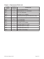
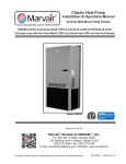
Chapter 1:
Chapter 2:
Chapter 3:
Chapter 4:
CR330
Owner’s Manual
Overview...............................................................................................2
Installing the CR330...............................................................................2
Maintenance of the CR330......................................................................5
Replacement Parts List...........................................................................6
This is the safety alert symbol
. When you see this symbol on the CR330 and in the instruction
manuals be alert to the potential for personal injury. Understand the signal word DANGER,
WARNING and CAUTION. These words are used to identify levels of the seriousness of the
hazard.
DANGER Failure to comply will result in death or severe personal injury and/or property
damage.
WARNINGFailure to comply could result in death or severe personal injury and/or property
damage.
CAUTION Failure to comply could result in minor personal injury and/or property damage.
IMPORTANT is used to point out helpful suggestions that will result in improved installation,
reliability or operation.
CAUTION
Certain components will run at fairly high temperatures. Exercise care in working around
operating equipment. Do not touch operating machinery without the aid of qualified
personnel, as referred to above.
Manufactured by:
Marvair Division of AIRXCEL , Inc
®
®
PO Box 400 • Cordele, GA 31010
156 Seedling Dr. • Cordele, GA 31015
(229) 273-3636 • Fax (229) 273-5154
Email: [email protected]
www.marvair.com
Marvair Marine UK
®
Unit B8 • Arena Business Centre • Holyrood Close
Poole, Dorset BH17 7FL.
+44 1202 606405
www.marvair.co.uk
Part #01563 10/09-3
Supersedes 10/07-2
CR330 Owner’s Manual 10/09
Page 1 of 6
Chapter 1 - Overview
The Marvair CR330 removes the condensate water produced during the cooling cycle of your
Marvair reverse cycle air conditioner and discharges the condensate into the air conditioner’s
outlet water line. The condensate is pumped overboard any time the air conditioner’s
circulation pump is working and sufficient condensate is in the condensate pan of your Marvair
unit. By operating on the Venturi effect, a separate condensate pump is not required.
A water filter/strainer, a reducer and a check valve are also provided and must be installed with
the CR330. The filter prevents debris from entering the CR330 and obstructing the water flow.
The check valve allows the condensate to flow in only one direction.
DANGER
•• The flow rate of the pump for the Marvair unit must be at least 1.00 GPM (3.79 LPM). If
the flow rate is less than this, the CR330 may not remove the condensate.
•• The seacock or ball valve in the air conditioner’s discharge water line must be closed
when installing the CR330. Failure to close the seacock or ball valve may result in the
flooding or sinking of the boat.
•• A check valve (supplied) MUST be installed in the condensate line as described in the
instructions. Failure to close the check valve may result in the flooding or sinking of the
boat.
Chapter 2 - Installing the CR330
CAUTION
Before installing the CR330, turn the circuit breaker off to the air conditioner and to the water
pump, if the pump has a separate breaker. If the pump turns on while the seacock or ball
valve is closed, damage to the pump may occur
The CR330 is installed into the outlet water line of the Marvair air conditioner. The discharge
water flows through the CR330 to the overboard thru hull fitting. Condensate from the
drain pan flows into the CR330 and is pulled overboard by the discharge water from the air
conditioner. See Figure No. 1.
Included in the installation materials are ½” clear tubing and 5/8” clear tubing. Various lengths
of this tubing must be cut to connect the components. To optimize the performance of the
system, be sure to follow the recommendations for the lengths of tubing. See Figure 1.
Locate the outlet (discharge) water line on your Marvair air conditioner. Follow the water line,
looking for a suitable place to install the CR330.
• The CR330 must be secured to a bulkhead to prevent movement while the boat is
underway.
• The CR330 does not have to be level, but the minimizing of bends in the tubing will improve
the performance of the CR330.
• The filter/strainer must be checked and cleaned regularly. Put the filter/strainer in an easily
accessible place.
• Use pipe dope to seal all threaded connections.
CR330 Owner’s Manual 10/09
Page 2 of 6
1.
Cut the water outlet line between the air conditioner and the thru hull fitting where the
CR330 is to be installed.
2.
The discharge water from the Marvair unit MUST flow through the CR330 in the proper
direction. See figure 1.
a. Screw the 5/8” barb x ½” MPT fitting into the inlet, the end with the FEMALE threads
of the CR330, as shown in figure 1. Slip the 5/8” discharge water line from the Marvair
unit over the barbs and secure the water line with 5/8” stainless steel hose clamps. To
prevent the CR330 from moving while underway, secure the water line with two hold
down clamps. If the CR330 moves, the lines may loosen and leak, causing the boat to
flood.
b. Screw the ½’ x ½” coupling onto the end of the CR330 with the MALE threads. Screw
the 5/8” barb x ½” FPT fitting into the coupling. Use pipe dope to seal all threaded
connections. Slip the 5/8” water line from the thru hull over the barbs and secure the
water line with 5/8” stainless steel hose clamps. To prevent the CR330 from moving
while underway, secure the water line with two hold down clamps. If the CR330
moves, the lines may loosen and leak, causing the boat to flood.
Condensate line assembly. Refer to Figure 1.
3.
Install the 5/8” hose barb x 5/8” fitting into the inlet side of the filter/strainer. Install the ½”
MPT x ¼” barb fitting into the discharge end of the filter/strainer. Use pipe dope to seal
each threaded connection.
4.
Cut a 12” (30.5 cm) piece of 5/8” tubing. Connect one end of the clear 5/8” tubing to the
condensate fitting on the drain pan of the Marvair air conditioner. Secure this connection
with a 5/8” screw type stainless steel screw type hose clamp. Install hold down clamps to
prevent the line from moving.
CAUTION
Water must flow in the proper direction through the filter strainer. On the side of the strainer
is an arrow that indicates the correct direction. Make sure the water flow is aligned with the
arrow.
5.
Connect the other end of this 5/8” tubing to the inlet side of the filter/strainer. Secure this
connection with a 5/8” stainless steel screw type hose clamp.
6.
Cut a 2-1/2” (6 cm) piece 1/4” clear tubing and connect it to the 1/4” end to the filter/
strainer. Secure with a 1/4” stainless steel screw type clamp. Connect the other end of the
1/4” tubing to the check valve and secure with 1/4” stainless steel screw type hose clamp.
Install hold down clamps to prevent the line from moving.
CAUTION
The check valve allows water to flow in one direction-from the condensate drain pan into
the CR330. To determine the proper orientation of the check valve, blow into one end of the
check valve. If air passes freely through the valve, this is the correct direction for the water
flow.
CR330 Owner’s Manual 10/09
Page 3 of 6
7.
Cut a 7 ft. (210 cm) piece of the ¼” tubing. Connect one end to the check valve and the
other end to the CR330. Secure both connections with ¼” stainless steel screw type hose
clamps.
8.
Open the seacock or ball valve.
9.
Turn the circuit breaker for the air conditioner to the on position. If the water pump has a
separate breaker, turn this breaker on.
10. Lower the temperature set point of the air conditioner so that it is below room temperature
and the air conditioner begins operation and cool air is being produced.
11. With the air conditioner running, pour 2-3 cups (1/2 liter) of clean water into the
condensate drain pan of the air conditioner. The condensate water should begin to
immediately flow from the drain pan through the clear hose and into the CR330.
12. Check all connections to make sure that they are tight and secure.
13. Make sure all lines and tubing are free of kinks.
Figure 1.
CR330 Owner’s Manual 10/09
Page 4 of 6
Chapter 3 - Maintenance of the CR330
Even though the CR330 condensate removal system has no moving parts, regular
maintenance and inspection of the system is essential for proper operation. The most
important task is to check the filter/strainer and to make sure it is clean and not obstructed.
WARNING
Failure to clean the filter/strainer may cause the condensate to overflow the condensate drain
pan causing damage to or flooding of the boat.
1. The condensate pan must be keep clean of mold and debris that could clog the filter/
strainer. Inspect the drain pan regularly to make sure it is clean.
2. If the condensate is not being removed from condensate pan and there are no kinks or
obstructions in the lines or tubing, the filter/strainer should be cleaned.
3. To clean the strainer:
a. Unscrew the plastic bulb on the strainer,
b. Take out the wire mesh strainer,
c. Spray off the wire mesh with water or using a wire brush, gently remover debris form the
screen.
d. Reassemble the components.
4. Cleaning of the CR330. Should the CR330 become clogged, it can be cleaned with
pressurized water. Alternately, a small probe, e.g., a paper clip, can be used to remove
obstructions from the orifice.
CR330 Owner’s Manual 10/09
Page 5 of 6
Chapter 4 - Replacement Parts List
PART
NUMBER
90169
NUMBER ON
DRAWING
DESCRIPTION
12
CR330 condensate remover
92006
5
Strainer/filter with ½” FPT connections
20371
10
1/4” x 1/4” Check valve
90168
4
5/8” Barb x 1/2” FPT coupling
90632
3
Stainless Steel screw type hose clamp for 5/8” tubing
90758
7
Stainless Steel screw type hose clamp for 1/4” tubing
81216
8, 11
1/4” ID clear tubing
20327
1
5/8” ID clear tubing
40450
6
1/4” barb x 1/2” MPT adapter
01568
2
Hold down clamp for 5/8” tubing
01567
9
Hold down strap for 1/2” tubing
01569
13
Hold down strap for the CR330
90398
14
5/8” barb x 1/2” MPT fitting
CR330 Owner’s Manual 10/09
Page 6 of 6