1
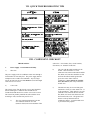
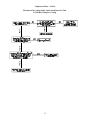
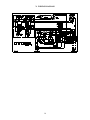
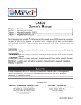
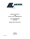
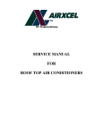
SERVICE MANUAL
FOR
6531 SERIES
ELEVATOR AIR CONDITIONERS
TABLE OF CONTENTS
I.
Warnings . . . . . . . . . . . . . . . . . . . . . . . . . . . . . . . . . . . . . . . . . . . . . . . . . . . . . . . .
2
II.
Component Match-Up . . . . . . . . . . . . . . . . . . . . . . . . . . . . . . . . . . . . . . . . . . . . .
2
III.
Specifications And Unit Identification . . . . . . . . . . . . . . . . . . . . . . . . . . . . . . . .
3
IV.
Wall Thermostat Operation (7330-324) . . . . . . . . . . . . . . . . . . . . . . . . . . . . . . .
4
V.
Sequence Of Operation . . . . . . . . . . . . . . . . . . . . . . . . . . . . . . . . . . . . . . . . . . . .
5
VI.
Electrical Components Identification . . . . . . . . . . . . . . . . . . . . . . . . . . . . . . . . .
6
VII.
Quick Troubleshooting Tips . . . . . . . . . . . . . . . . . . . . . . . . . . . . . . . . . . . . . . . .
7
VIII.
Component Checkout . . . . . . . . . . . . . . . . . . . . . . . . . . . . . . . . . . . . . . . . . . . . . .
7
IX.
Electrical Flow Charts . . . . . . . . . . . . . . . . . . . . . . . . . . . . . . . . . . . . . . . . . . . . . .
11
X.
Wiring Diagram . . . . . . . . . . . . . . . . . . . . . . . . . . . . . . . . . . . . . . . . . . . . . . . . . . .
16
I. WARNINGS
IMPORTANT NOTICE
WARNING - SHOCK HAZARD
These instructions are for the use of qualified individuals
specially trained and experienced in installation of this type
equipment and related system components.
To prevent the possibility of severe personal injury or
equipment damage due to electrical shock, always be sure
the electrical power source to the appliance is
disconnected during installation.
Installation and service personnel are required by some states
to be licensed. PERSONS NOT QUALIFIED SHALL NOT
INSTALL NOR SERVICE THIS EQUIPMENT.
CAREFULLY FOLLOW ALL INSTRUCTIONS AND
WARNINGS IN THIS BOOKLET TO AVOID DAMAGE
TO THE EQUIPMENT, PERSONAL INJURY OR FIRE.
NOTE
WARNING
The words “Shall” or “Must” indicate a requirement which is
essential to satisfactory and safe product performance.
Improper installation may damage equipment, can create
a hazard and will void the warranty.
The words “Should” or “May” indicate a recommendation or
advice which is not essential and not required but which may
be useful or helpful.
The use of components not tested in combination with this
unit will void the warranty, may make the equipment in
violation of state codes, may create a hazard and may ruin
the equipment.
II. COMPONENT MATCH-UP
1.
6531B692 Package Air Conditioner.
2.
2
6531-625 Accessory Kit (Optional)
III. SPECIFICATIONS AND UNIT
IDENTIFICATION
PACKAGE AIR CONDITIONER MODEL NUMBER BREAKDOWN
6
5
3
1
-
6
9
2
1 - 12 VDC Control Voltage
2 - 24 VAC Control Voltage
8 - No Start Kit
9 - Start Kit Included
Model Series
Revision
Letter
6 - Panasonic Compressor(s)
7 - Sanyo Compressor(s)
8 - Tecumseh Compressor(s)
SPECIFICATIONS
3
IV. WALL THERMOSTAT OPERATION
FOR 7330-324
1.
2.
3.
1°F rated differential
Shrouded contacts
Heat anticipator - .15 - .8 amp (self-adjusting)
Wiring: RC - Control Wiring Supply - A/C
RH or 4 - Control Wiring Supply - Heat
Y - Compressor Relay Coil
G - Fan Relay Coil
W - Furnace
THERMOSTAT OPERATION
4
V. SEQUENCE OF OPERATIONS
5
VI. ELECTRICAL COMPONENTS
IDENTIFICATION
PART #
1
2
3
4
5
6
7
8
ns
ns
ns
DESCRIPTION
Control Board
Coil Sensor
Fan Relay
Heater Relay
Start Capacitor
Heat Element
Limit Switch
Plug Assembly
Transformer
Run Capacitor
Fan Capacitor
6
VII. QUICK TROUBLESHOOTING TIPS
VIII. COMPONENT CHECKOUT
other wires. All switches, fuses, circuit breakers,
disconnects, etc. should be in this line.
THINK SAFETY
1.
Power Supply - from Commercial Utility
1)
Wire Size
b)
The wire with the white insulation is the
neutral. There should be 115 volts
(domestic USA) between the neutral and the
hot (black) wire, but there should be 0 volts
between the neutral and the ground (the
green wire or the frame of the air
conditioner). There must be no switches,
fuses, disconnects, etc. of any kind in the
neutral wire.
c)
The third wire may be covered with green
insulation or it may be a bare metal wire. It
is the ground wire. There must be 115 volts
(domestic USA) between this wire and the
hot (black) wire and 0 volts between it and
the neutral (white) wire. The ground wire
must be securely fastened to the air
conditioner cabinet. A green headed screw
is provided for this purpose.
The power supply to the air conditioner must come through a
circuit breaker or time delay fuse. The power supply must be
20 amperes and 12 AWG wire minimum. Any size larger
wire at any time may be used and should be used if the length
of the wire is over 32 feet.
2)
Color Code
The electric power from the electric service panel should be
delivered through a 3 conductor cable and the Service
Technician should check to be sure the color code is correct.
The electrician probably installed the cable with the colors
according to code, but don’t bet your life on it.
a)
The wire with black insulation is the hot
wire and there should be 115 volts
(domestic USA) between it and either of the
7
3)
Voltage
1)
The voltage (electrical pressure) at the unit should be 115
volts (domestic USA) and all electrical components will
perform best at the correct voltage. However, the voltage will
vary and the air conditioning system will perform
satisfactorily within plus or minus 10% of the rated (115)
voltage (domestic USA). Therefore, the voltage has to be
between 103.5 volts and 126.5 volts.
The switch contains a heater which
increases in temperature as the current
increases. The higher temperature warps
the switch and will cause it to open before
the windings reach a dangerous
temperature.
2)
2.
High Amperes (Current)
Power Supply - Generated By On-board Motor
Generator
High Temperature (Thermal)
The switch is clamped tightly against the
compressor housing and located close to the
windings. Therefore, as the windings reach
a higher temperature, it takes less current to
cause the switch to open.
If the power supply for the recreational vehicle is supplied by
an on-board motor generator, its wiring may be identical to
the commercial power described above.
There are, however, some motor generators on which both the
current carrying leads are insulated from the ground. That is
to say; there is no grounded neutral, so there will be 115 volts
(domestic USA) between the black and white leads, but there
will be 0 volts between either lead and ground.
As can be seen, the switch is always affected by a
combination of current to the compressor and winding
temperature.
WARNING: The service technician must keep in mind
when checking to make sure that the power is turned off –
check only between the hot (black) lead and the neutral
(white) lead. The black lead could still be hot even though
there is 0 volts between it and ground.
The air conditioning unit has one double end shaft fan motor.
On one shaft end is mounted a centrifugal or squirrel cage
blower which draws air (return air) out of the recreational
vehicle and blows the conditioned air down into the
recreational vehicle. On the other shaft end is mounted an
axial flow or propellor type fan which circulates outdoor air
through the condenser coil.
3.
5.
Compressor Motor
The compressor motor is located inside the hermetic
compressor housing and is therefore, not accessible for
service or visual observation in the field. However, the motor
winding condition can be analyzed by using an ohm meter.
Be sure to remove all the leads from the compressor terminals
before making this check.
1.
If the resistance between any two terminals
is 0 ohms, the motor windings are shorted.
2.
If the resistance between any terminal and
the compressor housing is anything but
infinity, the winding is grounded.
An important step in installing a replacement fan motor is to
check the direction of rotation before it is installed. On all
models, the condenser fan pulls the air through the coil.
Fan Motor Check Procedure
If a fan motor refuses to perform properly, it can be checked
in the following manner:
1.
4.
Fan Motor
Be sure the motor leads are connected to the proper
points –
a)
The black wire from the motor connects to a
black wire inside a wire nut then the black
wire connects through the disconnect plug
to the selector switch. The red wire from
the motor connects to a red wire in a wire
nut then the red wire connects through the
disconnect plug to the selector switch.
b)
The white wire from the motor connects to
a white wire in a wire nut then the white
wire connects through the disconnect plug
to the thermostat.
Overload Switch
Mounted on the outside of the compressor housing is a two
terminal Overload switch. The switch is connected in series
with the common terminal. If the switch opens, it will cut the
power to the compressor motor. The switch will open as the
result of either or both of two conditions that could be
harmful to the compressor.
8
c)
2.
The brown wires from the motor connect to
the fan capacitor.
Capacitor Check
There are several capacitor test devices available. The ohm
meter is one of them. The ohm meter cannot verify a
capacitors MFD (microfarrad) value. However, the following
procedures will show you how to use an ohm meter to
determine if the capacitor is good, open, shorted or grounded.
To check the motor winding resistance, carefully
check the resistance between each of the wires and
ground (preferably a copper refrigerant tube for a
good connection). These readings must be infinity.
Any continuity means the windings are grounded.
Before testing any capacitor, always perform the following
procedure:
If there is a reading of 0 between any two leads, the motor is
shorted and is no good. If there is a reading of infinity
between any two leads, the winding is open and the motor is
no good.
a)
Disconnect all electrical power to the air conditioner.
b)
Discharge the capacitor with a 20,000 ohm (approx.
3 watt) resistor or larger.
The low voltage relays are used in the control circuits to close
or open a set of high voltage contacts. When this happens, it
either makes or breaks a circuit. To check the relay you must
first; 1) shut the power off to the unit, 2) take the line voltage
wires off the relay, 3) apply 24 volts to the coil side of the
relay, and 4) take an ohm-meter and check to see if the
contacts open and close.
c)
You may discharge capacitors with a standard volt
meter if you use a scale over 500 volts and touch the
leads (one lead to each side of the capacitor), the volt
meter will discharge the capacitor.
d)
Identify and disconnect the wiring from the
capacitor.
7.
e)
Set and zero the ohm meter on the “highest” scale.
6.
Relays
Transformers
The transformer is used in the circuit to convert 115 VAC
and step it down to 24 VAC. To check the transformer,
simply take a voltmeter and check for 24 VAC between the
red and blue wires coming from the transformer.
8.
When testing for a good, open or shorted capacitor,
perform the following checks: Place the ohm meter
leads across the capacitor terminals (one lead on
each terminal) and perform a continuity test. Then
observe the action of the meter needle or indicator.
Reverse the leads and test again. The result should
be the same. Note: If the capacitor had not been
properly discharged, a false reading could be
indicated on the first test. Always test several times
(reversing the leads with each test). This will verify
the capacitors condition.
Heating Element
The heating element is a resistance heater of 1600 watts
(5600 BTUH) capacity and is connected across the line when
the selector is set for heating and the thermostat is calling for
heat. The current draw of the heater (element only) will be
13.9 amperes at 120 volts (domestic USA models).
9.
Limit Switch
The limit switch is a safety switch and is mounted in the
heating element frame. It will open and break the circuit on
temperature rise in case the air flow through the heater
becomes low enough to cause the heater to overheat.
10.
Run Capacitors
The purpose of the run capacitors is to give the motors
starting torque and to maintain high power factor during
running. The run capacitors are always connected between
the start and run or main terminals of the motor.
9
Good Capacitor
Shorted Capacitor
If the capacitor is good, the indicator will move from infinity
(the left side), up towards zero ohms and slowly return back
to infinity. Reverse the leads and test again. The result
should be the same.
If the capacitor is shorted, the indicator will move toward and
sometimes hit zero ohms, and will stay there. This indicates
a completed circuit through the inside of the capacitor
(shorted). Shorted capacitors are defective and must be
replaced.
CAPACITOR
HIGH
SHORT
LOW
OHM METER
Indicator moves to the right side
of the scale and stays there
(indicating a completed circuit).
The capacitor is shorted.
HIGH
LOW
OK
Grounded Capacitor
When testing for a grounded capacitor, perform a continuity
check between each terminal on the capacitor and the bare
metal of the capacitor case. Any indication of a circuit
(constant resistance) from either terminal to case, indicates a
grounded capacitor. Grounded capacitors are defective and
must be replaced.
Indicator sweeps back and forth
as shown above. Capacitor is good.
Open Capacitor
If the capacitor is open, the indicator will show no deflection
or movement. Reverse the leads and test again. If there is no
indicator movement on the second test, the capacitor is open.
Open capacitors are defective and must be replaced.
CAPACITOR
OPEN
HIGH
LOW
OHM METER
Indicator shows no movement.
Needle stays to the left side. If needle
shows no movement after reversing the
leads, the capacitor is open.
HIGH
GROUNDED
LOW
Indicator moves to the right side of
the scale and stays there
(indicating a completed circuit).
The capacitor is grounded.
11.
Start Capacitor
Some models use a start capacitor and a start relay to give the
compressor high starting torque. The compressor will,
therefore, start against normal pressure differences (head
pressure minus suction pressure) even when shut down for a
short period of time. The start relay will disconnect the start
10
capacitor when the motor reaches approximately 75%
running speed.
2)
A high voltage coil internally between terminals #5
and #2 to actuate the contacts. The coil is too weak
on line voltage to actuate the contacts, but it is
connected in series with the start winding and it gets
the generated voltage of the start winding portion of
the compressor motor. This generated voltage is
much higher than line voltage and varies with the
speed of the motor. Therefore, since the relay is
designed to open the contacts at 75% of normal
running voltage (measured between terminals #5 and
#2), the contacts will open (thus disconnect the start
capacitor) at approximately 75% of normal running
speed.
13.
Thermister
Notice the resistor which is soldered to the terminals of the
start capacitor. The resistor is there to discharge the
capacitor after the relay disconnects it from the circuit. This
resistor must be in place or the capacitor will discharge
through the relay when the compressor is shut down and in
doing so, will damage the relay contacts.
12.
Start (Potential) Relay
The start relay consists of –
1)
Normally closed contacts internally between
terminals #1 and #2 which switch in the start
capacitor in parallel to the run capacitor during
shutdown and then switch out the start capacitor
when the motor reaches approximately 75% normal
running speed.
The thermister is a freeze protection device installed in the
compressor relay circuit to prevent evaporator coil freeze-ups.
This device is a semi-conductor which has electrical
resistance that varies with temperature. The thermister cutout
temperature is 31°F ± 3° and reset temperature is 53°F.
IX. ELECTRICAL FLOW CHARTS
Nothing Runs
Thermostat In Cooling Mode And Turned Down So
That It Will Be Calling For Cooling
11
Fan Runs - No Compressor
Turn Thermostat To Cool And Turn Temperature Down So
That The Thermostat Should Be Calling For Cooling
12
Compressor Runs - No Fan
Thermostat In Cooling Mode And Turned Down So That
It Will Be Calling For Cooling
13
Fan Runs - No Heat
Thermostat In Heating Mode and Turned Up So That
It Will Be Calling For Heat
14
Heat Runs - No Fan
Thermostat In Heating Mode And Turned Up So
That It Will Be Calling For Heat
15
X. WIRING DIAGRAM
16
RV Products
A Division of Airxcel, Inc.
P.O. Box 4020
Wichita, KS 67204
1976-292 (1-99) PP