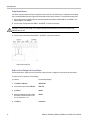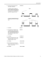
1
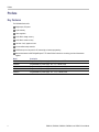
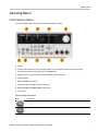
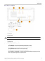
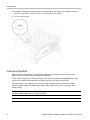
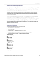
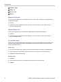
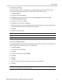
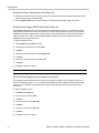
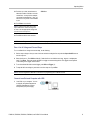
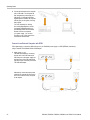
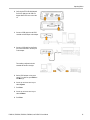
x
PWS4205, PWS4305, PWS4323, PWS4602, and PWS4721
Linear DC Power Supplies
ZZZ
User Manual
*P071276101*
071-2761-01
xx
PWS4205, PWS4305, PWS4323, PWS4602, and PWS4721
Linear DC Power Supplies
ZZZ
User Manual
www.tektronix.com
071-2761-01
Copyright © Tektronix. All rights reserved. Licensed software products are owned by Tektronix or its subsidiaries or suppliers, and are
protected by national copyright laws and international treaty provisions.
Tektronix products are covered by U.S. and foreign patents, issued and pending. Information in this publication supersedes that in all
previously published material. Specifications and price change privileges reserved.
TEKTRONIX and TEK are registered trademarks of Tektronix, Inc.
Contacting Tektronix
Tektronix, Inc.
14150 SW Karl Braun Drive
P.O. Box 500
Beaverton, OR 97077
USA
For product information, sales, service, and technical support:
In North America, call 1-800-833-9200.
Worldwide, visit www.tektronix.com to find contacts in your area.
Warranty
Tektronix warrants that the product will be free from defects in materials and workmanship for a period of three (3) years from the date
of original purchase from an authorized Tektronix distributor. If the product proves defective during this warranty period, Tektronix, at its
option, either will repair the defective product without charge for parts and labor, or will provide a replacement in exchange for the
defective product. Batteries are excluded from this warranty. Parts, modules and replacement products used by Tektronix for warranty
work may be new or reconditioned to like new performance. All replaced parts, modules and products become the property of Tektronix.
In order to obtain service under this warranty, Customer must notify Tektronix of the defect before the expiration of the warranty
period and make suitable arrangements for the performance of service. Customer shall be responsible for packaging and shipping
the defective product to the service center designated by Tektronix, shipping charges prepaid, and with a copy of customer proof of
purchase. Tektronix shall pay for the return of the product to Customer if the shipment is to a location within the country in which
the Tektronix service center is located. Customer shall be responsible for paying all shipping charges, duties, taxes, and any other
charges for products returned to any other locations.
This warranty shall not apply to any defect, failure or damage caused by improper use or improper or inadequate maintenance and
care. Tektronix shall not be obligated to furnish service under this warranty a) to repair damage resulting from attempts by personnel
other than Tektronix representatives to install, repair or service the product; b) to repair damage resulting from improper use or
connection to incompatible equipment; c) to repair any damage or malfunction caused by the use of non-Tektronix supplies; or
d) to service a product that has been modified or integrated with other products when the effect of such modification or integration
increases the time or difficulty of servicing the product.
THIS WARRANTY IS GIVEN BY TEKTRONIX WITH RESPECT TO THE PRODUCT IN LIEU OF ANY OTHER WARRANTIES,
EXPRESS OR IMPLIED. TEKTRONIX AND ITS VENDORS DISCLAIM ANY IMPLIED WARRANTIES OF MERCHANTABILITY OR
FITNESS FOR A PARTICULAR PURPOSE. TEKTRONIX’ RESPONSIBILITY TO REPAIR OR REPLACE DEFECTIVE PRODUCTS
IS THE SOLE AND EXCLUSIVE REMEDY PROVIDED TO THE CUSTOMER FOR BREACH OF THIS WARRANTY. TEKTRONIX
AND ITS VENDORS WILL NOT BE LIABLE FOR ANY INDIRECT, SPECIAL, INCIDENTAL, OR CONSEQUENTIAL DAMAGES
IRRESPECTIVE OF WHETHER TEKTRONIX OR THE VENDOR HAS ADVANCE NOTICE OF THE POSSIBILITY OF SUCH
DAMAGES.
[W16 – 15AUG04]
Table of Contents
Table of Contents
General Safety Summary . .. . .. . .. . .. . .. . .. . .. . .. . .. . .. . .. . .. . .. . .. . .. . .. . .. . .. . .. . .. . .. . .. . .. . .. . .. . .. . .. . .. . .. . .. . .. . .. . .. . .. . .. . . . . iii
Compliance Information .. . .. . .. . .. . .. . .. . .. . .. . .. . .. . .. . .. . .. . .. . .. . .. . .. . .. . .. . .. . .. . .. . .. . .. . .. . .. . .. . .. . .. . .. . .. . .. . .. . .. . .. . .. . .. . v
EMC Compliance. . .. . .. . .. . .. . .. . .. . .. . .. . .. . .. . .. . .. . .. . .. . .. . .. . .. . .. . .. . .. . .. . .. . .. . .. . .. . .. . .. . .. . .. . .. . .. . .. . .. . .. . .. . .. . .. . v
Safety Compliance .. . .. . .. . .. . .. . .. . .. . .. . .. . .. . .. . .. . .. . .. . .. . .. . .. . .. . .. . .. . .. . .. . .. . .. . .. . .. . .. . .. . .. . .. . .. . .. . .. . .. . .. . .. . .. vii
Environmental Considerations.. . .. . .. . .. . .. . .. . .. . .. . .. . .. . .. . .. . .. . .. . .. . .. . .. . .. . .. . .. . .. . .. . .. . .. . .. . .. . .. . .. . .. . .. . .. . .. . .. . ix
Preface .. . .. . .. . .. . .. . .. . .. . .. . .. . .. . .. . .. . .. . .. . .. . .. . .. . .. . .. . .. . .. . .. . .. . .. . .. . .. . .. . .. . .. . .. . .. . .. . .. . .. . .. . .. . .. . .. . .. . .. . .. . .. . .. . x
Key Features .. . .. . .. . .. . .. . .. . .. . .. . .. . .. . .. . .. . .. . .. . .. . .. . .. . .. . .. . .. . .. . .. . .. . .. . .. . .. . .. . .. . .. . .. . .. . .. . .. . .. . .. . .. . .. . .. . .. . x
Getting Started. .. . .. . .. . .. . .. . .. . .. . .. . .. . .. . .. . .. . .. . .. . .. . .. . .. . .. . .. . .. . .. . .. . .. . .. . .. . .. . .. . .. . .. . .. . .. . .. . .. . .. . .. . .. . .. . .. . .. . .. . 1
Standard Accessories.. . .. . .. . .. . .. . .. . .. . .. . .. . .. . .. . .. . .. . .. . .. . .. . .. . .. . .. . .. . .. . .. . .. . .. . .. . .. . .. . .. . .. . .. . .. . .. . .. . .. . .. . .. . 1
Options and Optional Accessories . .. . .. . .. . .. . .. . .. . .. . .. . .. . .. . .. . .. . .. . .. . .. . .. . .. . .. . .. . .. . .. . .. . .. . .. . .. . .. . .. . .. . .. . .. . .. . 1
Specifications.. . .. . .. . .. . .. . .. . .. . .. . .. . .. . .. . .. . .. . .. . .. . .. . .. . .. . .. . .. . .. . .. . .. . .. . .. . .. . .. . .. . .. . .. . .. . .. . .. . .. . .. . .. . .. . .. . .. . 2
Operating Requirements.. . .. . .. . .. . .. . .. . .. . .. . .. . .. . .. . .. . .. . .. . .. . .. . .. . .. . .. . .. . .. . .. . .. . .. . .. . .. . .. . .. . .. . .. . .. . .. . .. . .. . .. . 3
Installing the System . .. . .. . .. . .. . .. . .. . .. . .. . .. . .. . .. . .. . .. . .. . .. . .. . .. . .. . .. . .. . .. . .. . .. . .. . .. . .. . .. . .. . .. . .. . .. . .. . .. . .. . .. . .. . 4
Cleaning . . .. . .. . .. . .. . .. . .. . .. . .. . .. . .. . .. . .. . .. . .. . .. . .. . .. . .. . .. . .. . .. . .. . .. . .. . .. . .. . .. . .. . .. . .. . .. . .. . .. . .. . .. . .. . .. . .. . .. . .. . 6
Operating Basics . .. . .. . .. . .. . .. . .. . .. . .. . .. . .. . .. . .. . .. . .. . .. . .. . .. . .. . .. . .. . .. . .. . .. . .. . .. . .. . .. . .. . .. . .. . .. . .. . .. . .. . .. . .. . .. . .. . .. . 7
Front Panel at a Glance. .. . .. . .. . .. . .. . .. . .. . .. . .. . .. . .. . .. . .. . .. . .. . .. . .. . .. . .. . .. . .. . .. . .. . .. . .. . .. . .. . .. . .. . .. . .. . .. . .. . .. . .. . 7
Rear Panel at a Glance . .. . .. . .. . .. . .. . .. . .. . .. . .. . .. . .. . .. . .. . .. . .. . .. . .. . .. . .. . .. . .. . .. . .. . .. . .. . .. . .. . .. . .. . .. . .. . .. . .. . .. . .. 11
Front-panel Operation.. . .. . .. . .. . .. . .. . .. . .. . .. . .. . .. . .. . .. . .. . .. . .. . .. . .. . .. . .. . .. . .. . .. . .. . .. . .. . .. . .. . .. . .. . .. . .. . .. . .. . .. . .. 12
Index
PWS4205, PWS4305, PWS4323, PWS4602, and PWS4721 User Manual
i
Table of Contents
ii
PWS4205, PWS4305, PWS4323, PWS4602, and PWS4721 User Manual
General Safety Summary
General Safety Summary
Review the following safety precautions to avoid injury and prevent damage to this product or any products connected to it.
To avoid potential hazards, use this product only as specified.
Only qualified personnel should perform service procedures.
To Avoid Fire or Personal Injury
Use proper power cord. Use only the power cord specified for this product and certified for the country of use.
Use proper voltage setting. Before applying power, ensure that the line selector is in the proper position for the
source being used.
Ground the product. This product is grounded through the grounding conductor of the power cord. To avoid electric
shock, the grounding conductor must be connected to earth ground. Before making connections to the input or output
terminals of the product, ensure that the product is properly grounded.
Observe all terminal ratings. To avoid fire or shock hazard, observe all ratings and markings on the product. Consult the
product manual for further ratings information before making connections to the product.
Power disconnect. The power switch disconnects the product from the power source. See instructions for the location.
Do not block the power switch; it must remain accessible to the user at all times.
Do not operate without covers. Do not operate this product with covers or panels removed.
Do not operate with suspected failures. If you suspect that there is damage to this product, have it inspected by
qualified service personnel.
Avoid exposed circuitry. Do not touch exposed connections and components when power is present.
Use proper fuse. Use only the fuse type and rating specified for this product.
Do not operate in wet/damp conditions.
Do not operate in an explosive atmosphere.
Keep product surfaces clean and dry.
Provide proper ventilation. Refer to the manual’s installation instructions for details on installing the product so it has
proper ventilation.
PWS4205, PWS4305, PWS4323, PWS4602, and PWS4721 User Manual
iii
General Safety Summary
Terms in This Manual
These terms may appear in this manual:
WARNING. Warning statements identify conditions or practices that could result in injury or loss of life.
CAUTION. Caution statements identify conditions or practices that could result in damage to this product or other property.
Symbols and Terms on the Product
These terms may appear on the product:
DANGER indicates an injury hazard immediately accessible as you read the marking.
WARNING indicates an injury hazard not immediately accessible as you read the marking.
CAUTION indicates a hazard to property including the product.
The following symbol(s) may appear on the product:
iv
PWS4205, PWS4305, PWS4323, PWS4602, and PWS4721 User Manual
Compliance Information
Compliance Information
This section lists the EMC (electromagnetic compliance), safety, and environmental standards with which the instrument
complies.
EMC Compliance
EC Declaration of Conformity – EMC
Meets intent of Directive 2004/108/EC for Electromagnetic Compatibility. Compliance was demonstrated to the following
specifications as listed in the Official Journal of the European Communities:
EN 61326-1 2006. EMC requirements for electrical equipment for measurement, control, and laboratory use. 1 2 3
CISPR 11:2003. Radiated and conducted emissions, Group 1, Class A
IEC 61000-4-2:2001. Electrostatic discharge immunity
IEC 61000-4-3:2002. RF electromagnetic field immunity
IEC 61000-4-4:2004. Electrical fast transient / burst immunity
IEC 61000-4-5:2001. Power line surge immunity
IEC 61000-4-6:2003. Conducted RF immunity
IEC 61000-4-11:2004. Voltage dips and interruptions immunity 4
EN 61000-3-2:2006. AC power line harmonic emissions
EN 61000-3-3:1995. Voltage changes, fluctuations, and flicker
European contact.
Tektronix UK, Ltd.
Western Peninsula
Western Road
Bracknell, RG12 1RF
United Kingdom
1
This product is intended for use in nonresidential areas only. Use in residential areas may cause electromagnetic interference.
2
Emissions which exceed the levels required by this standard may occur when this equipment is connected to a test object.
3
For compliance with the EMC standards listed here, high quality shielded interface cables should be used.
4
Output voltage, current limit, and output state upon restoration of AC input power after a power interruption are determined by user
preference settings. Under the factory default settings, output voltage and current limit values will be restored to the previous
settings, but output state will be set to off. Change the user preferences if restoration of previous output state upon restoration of
AC input power is desired.
PWS4205, PWS4305, PWS4323, PWS4602, and PWS4721 User Manual
v
Compliance Information
Australia / New Zealand Declaration of Conformity – EMC
Complies with the EMC provision of the Radiocommunications Act per the following standard, in accordance with ACMA:
CISPR 11:2003. Radiated and Conducted Emissions, Group 1, Class A, in accordance with EN 61326-1:2006.
Australia / New Zealand contact.
Baker & McKenzie
Level 27, AMP Centre
50 Bridge Street
Sydney NSW 2000, Australia
vi
PWS4205, PWS4305, PWS4323, PWS4602, and PWS4721 User Manual
Compliance Information
Safety Compliance
EC Declaration of Conformity – Low Voltage
Compliance was demonstrated to the following specification as listed in the Official Journal of the European Communities:
Low Voltage Directive 2006/95/EC.
EN 61010-1: 2001. Safety requirements for electrical equipment for measurement control and laboratory use.
U.S. Nationally Recognized Testing Laboratory Listing
UL 61010-1:2004, 2nd Edition. Standard for electrical measuring and test equipment.
Canadian Certification
CAN/CSA-C22.2 No. 61010-1:2004. Safety requirements for electrical equipment for measurement, control, and
laboratory use. Part 1.
Additional Compliances
IEC 61010-1: 2001. Safety requirements for electrical equipment for measurement, control, and laboratory use.
Equipment Type
Test and measuring equipment.
Safety Class
Class 1 – grounded product.
Pollution Degree Description
A measure of the contaminants that could occur in the environment around and within a product. Typically the internal
environment inside a product is considered to be the same as the external. Products should be used only in the environment
for which they are rated.
Pollution Degree 1. No pollution or only dry, nonconductive pollution occurs. Products in this category are generally
encapsulated, hermetically sealed, or located in clean rooms.
Pollution Degree 2. Normally only dry, nonconductive pollution occurs. Occasionally a temporary conductivity that is
caused by condensation must be expected. This location is a typical office/home environment. Temporary condensation
occurs only when the product is out of service.
Pollution Degree 3. Conductive pollution, or dry, nonconductive pollution that becomes conductive due to condensation.
These are sheltered locations where neither temperature nor humidity is controlled. The area is protected from direct
sunshine, rain, or direct wind.
Pollution Degree 4. Pollution that generates persistent conductivity through conductive dust, rain, or snow. Typical
outdoor locations.
PWS4205, PWS4305, PWS4323, PWS4602, and PWS4721 User Manual
vii
Compliance Information
Pollution Degree
Pollution Degree 2 (as defined in IEC 61010-1). Note: Rated for indoor use only.
Installation (Overvoltage) Category Descriptions
Terminals on this product may have different installation (overvoltage) category designations. The installation categories are:
Measurement Category IV. For measurements performed at the source of low-voltage installation.
Measurement Category III. For measurements performed in the building installation.
Measurement Category II. For measurements performed on circuits directly connected to the low-voltage installation.
Measurement Category I. For measurements performed on circuits not directly connected to MAINS.
Overvoltage Category
Overvoltage Category II (as defined in IEC 61010-1)
viii
PWS4205, PWS4305, PWS4323, PWS4602, and PWS4721 User Manual
Compliance Information
Environmental Considerations
This section provides information about the environmental impact of the product.
Product End-of-Life Handling
Observe the following guidelines when recycling an instrument or component:
Equipment recycling. Production of this equipment required the extraction and use of natural resources. The equipment
may contain substances that could be harmful to the environment or human health if improperly handled at the product’s
end of life. To avoid release of such substances into the environment and to reduce the use of natural resources, we
encourage you to recycle this product in an appropriate system that will ensure that most of the materials are reused
or recycled appropriately.
This symbol indicates that this product complies with the applicable European Union requirements according
to Directives 2002/96/EC and 2006/66/EC on waste electrical and electronic equipment (WEEE) and
batteries. For information about recycling options, check the Support/Service section of the Tektronix Web
site (www.tektronix.com).
Restriction of Hazardous Substances
This product is classified as Monitoring and Control equipment, and is outside the scope of the 2002/95/EC RoHS Directive.
PWS4205, PWS4305, PWS4323, PWS4602, and PWS4721 User Manual
ix
Preface
Preface
Key Features
The PWS4000 Series offer:
Single-output, DC power
3-year warranty
Linear regulation
0.03% Basic voltage accuracy
0.05% Basic current accuracy
Less than 5 mVpp ripple and noise
40 user-defined setup memories
USB Device port on rear panel for PC connectivity and remote programming
National Instruments LabVIEW SignalExpress™ TE Limited Edition Software for connecting your bench instruments
together
x
Model
Description
PWS4205
Programmable DC power supply. 20 V, 5 A, 1 channel, USB
PWS4305
Programmable DC power supply. 30 V, 5 A, 1 channel, USB
PWS4323
Programmable DC power supply. 32 V, 3 A, 1 channel, USB
PWS4602
Programmable DC power supply. 60 V, 2.5 A, 1 channel, USB
PWS4721
Programmable DC power supply. 72 V, 1.2 A, 1 channel, USB
PWS4205, PWS4305, PWS4323, PWS4602, and PWS4721 User Manual
Getting Started
Getting Started
Standard Accessories
Accessory
Tektronix part
number
PWS4205, PWS4305, PWS4323, PWS4602, and PWS4721 Power Supply User Manual (available
in 10 languages) Contains safety and installation information.
071-2761-XX to
071-2770-XX
Power Cord: based upon the international power option
(See page 1,
Options and
Optional
Accessories.)
Certificate of calibration
PWS4000 Linear Power Supplies Documentation Browser CD
063-4282-XX
National Instruments LabVIEW SignalExpress, Tektronix Limited Edition Communications Software
CD, Version 2.5.1
063-4253-00
Options and Optional Accessories
For the current list of accessories, upgrades, and options available for your PWS4000 Series Power Supply, visit the
Tektronix Web site, www.tektronix.com.
Table 1: Standard accessories
Accessory
Tektronix part
number
PWS4205, PWS4305, PWS4323, PWS4602, and PWS4721 Power Supply Technical Reference,
in English. Contains detailed information about the instrument, including specifications and how to
verify performance. Available for download from www.tektronix.com/manuals.
077-0480-XX
PWS4205, PWS4305, PWS4323, PWS4602, and PWS4721 Programmer Manual, in English.
Contains detailed information about remote control of the instrument. Available for download
from www.tektronix.com/manuals.
077-0481-XX
PWS4205, PWS4305, PWS4323, PWS4602, and PWS4721 User Manual
1
Getting Started
Table 1: Standard accessories (cont.)
Tektronix part
number
Accessory
Power Cord
One of the following:
North America (Option A0). The factory sets the 110V/220V selector switch
to 110 V.
Universal Euro (Option A1). The factory sets the 110V/220V selector switch
to 220 V.
United Kingdom (Option A2). The factory sets the 110V/220V selector switch
to 220 V.
Australia (Option A3). The factory sets the 110V/220V selector switch to 220 V.
Switzerland (Option A5). The factory sets the 110V/220V selector switch to
220 V.
China (Option A10). The factory sets the 110V/220V selector switch to 220 V.
India (Option A11). The factory sets the 110V/220V selector switch to 220 V.
Brazil (Option A12). The factory sets the 110V/220V selector switch to 220 V.
Tektronix GPIB to USB Adapter. Enables GPIB control of Tektronix instruments through the
USB port of Tektronix instruments
TEK-USB-488
Specifications
For more specifications, refer to the PWS4205, PWS4305, PWS4323, PWS4602, and PWS4721 Technical Reference.
Table 2: Electrical ratings for the power connection
Model
Line Selector
Switch Setting
Frequency
Fuse Rating
Max Power
PWS4205
110 V / 220 V
50 / 60 Hz
For 110 V: 5 A TH, 250 V
For 220 V: 2.5 A TH, 250 V
350 VA
PWS4305
110 V / 220 V
50 / 60 Hz
For 110 V: 5 A TH, 250 V
For 220 V: 2.5 A TH, 250 V
500 VA
PWS4323
110 V / 220 V
50 / 60 Hz
For 110 V: 5 A TH, 250 V
For 220 V: 2.5 A TH, 250 V
350 VA
PWS4602
110 V / 220 V
50 / 60 Hz
For 110 V: 5 A TH, 250 V
For 220 V: 2.5 A TH, 250 V
500 VA
PWS4721
110 V / 220 V
50 / 60 Hz
For 110 V: 5 A TH, 250 V
For 220 V: 2.5 A TH, 250 V
350 VA
Table 3: Environmental performance
2
Parameter
PWS4205
Temperature
Operating: +0 °C to +40 °C
PWS4305
PWS4323
PWS4602
PWS4721
PWS4205, PWS4305, PWS4323, PWS4602, and PWS4721 User Manual
Getting Started
Table 3: Environmental performance (cont.)
Parameter
PWS4205
PWS4305
PWS4323
PWS4602
Humidity
Operating:
5% to 95% relative humidity (% RH) at up to 40 °C, non-condensing
Altitude
Operating: 100% capability up to 2,000 meters.
PWS4721
Pollution Degree 2, For indoor use only
Nominal Voltage Ratings
There are two ranges for all models, selectable by the line-voltage selector switch. Check the voltage select switch on the
bottom of the power supply before turning it on: 110 V setting, 110 / 115 / 120 VAC; 220 V setting, 220 / 230 / 240 VAC.
Fluctuations must not exceed 10% of the nominal rated voltage.
Float Voltage Rating
Float voltage rating: up to 100 V (DC + peak AC) between earth ground and any output terminal.
Operating Requirements
1. Place the instrument on a bench or similar surface.
2. Before operating, ensure that the ambient temperature is between +0 °C and +40 °C (+32 °F to +104 °F).
WARNING. To ensure proper cooling, keep the front, sides, and rear of the instrument clear of obstructions.
WARNING. Observe all safety precautions listed in this manual before using this product and any associated instruments.
Although some instruments and accessories would be used with non-hazardous voltages, there are situations where
hazardous conditions may be present. This product is intended for use by qualified personnel who recognize shock hazards
and are familiar with the safety precautions required to avoid possible injury. Read and follow all installation, operation, and
maintenance information carefully before using the product. Refer to this manual for complete product specifications. Before
performing any maintenance, disconnect the line cord and all test cables. Operators of this instrument must be protected
from electric shock at all times. The responsible body must ensure that operators are prevented access and/or insulated from
every connection point. In some cases, connections must be exposed to potential human contact. Product operators in these
circumstances must be trained to protect themselves from the risk of electric shock. If the circuit is capable of operating at or
above 1000 volts, no conductive part of the circuit may be exposed.
WARNING. Use properly rated load wires. All load wires must be heavy enough not to overheat when carrying the maximum
short-circuit output current of the power supply. If there is more than one load, then any pair of load wires must be capable
of safely carrying the full-rated short-circuit output current of the power supply.
WARNING. Do not loosen any screw on this product, except those in the rear connector, which are intended to retain
attached external wires to the connector. There are no user serviceable components inside.
PWS4205, PWS4305, PWS4323, PWS4602, and PWS4721 User Manual
3
Getting Started
WARNING. To reduce risk of fire and shock, ensure the mains supply voltage fluctuations do not exceed 10% of the
operating voltage range.
Installing the System
This section contains information on how to install your PWS4000 power supply.
Unpack the instrument and check that you received all the items listed as standard accessories.
Check that you also received any other accessories that you ordered with your instrument.
Check the Tektronix Web site (www.tektronix.com) for the most current information.
To verify that the power supply is ready to use, follow these procedures:
Powering the Instrument On and Off
To power on the instrument follow these steps:
1. Make all the connections.
2. Properly set the 110 V / 220 V selector switch on the bottom of the instrument.
3. Connect the power cord that was provided with the instrument to the power connector on the rear panel. Connect the
power cord plug to a properly grounded electrical outlet.
4. Push the power button on the front panel.
To power off the instrument, push the front-panel power button.
WARNING. To satisfy safety requirements, always use load wires heavy enough not to overheat when carrying the maximum
short-circuit output current of the power supply. If there is more than one load, then every pair of load wires must be capable
of safely carrying the full-rated current of the power supply.
4
PWS4205, PWS4305, PWS4323, PWS4602, and PWS4721 User Manual
Getting Started
What to Do if the Power Supply Does Not Turn On
To solve problems you might encounter when turning on the instrument, follow these steps:
1. Verify that there is AC power to the power supply.
First, check that the AC power cord is firmly plugged into the power connector on the rear panel of the power supply.
You should also make sure that the AC power source you plugged the power supply into is energized. Then, check
that the power supply is turned on.
2. Verify the power-line voltage settings.
Check that the line voltage selector switch on the bottom of the instrument is set to the proper value for your country
(110 VAC or 220 VAC). Change the voltage setting if it is not correct.
NOTE. Under certain circumstances, powering the instrument from a mains voltage for which it is not configured can
cause the mains fuse to open.
3. Verify that the correct power-line fuse is installed.
If the fuse is damaged, replace the fuse for your power supply.
If you set the line selection to 110 V, use a 5 A, TH 250 V fuse.
If you set the line selection to 220 V, use a 2.5 A, TH 250 V fuse.
4. If you need more help, contact Tektronix.
Check the Output
The following procedures check that the power supply develops its rated outputs and properly responds to operation
from the front panel.
Voltage output check. To verify basic voltage functions without a load, follow these steps.
1. Remove all leads from the output connectors.
2. Turn on the power supply.
3. Push Shift and Menu (1). >Default Set should appear on the display.
4. Push Enter to bring up the default settings menu. No and Yes should appear on the display.
5. Push the right arrow button to select Yes. Push Enter to enable the default settings.
6. Push the front-panel On/Off button to enable the output. The OFF message in the display should turn off and the CV
display should turn on. The upper line of the display should show the actual output voltage and current. The lower line
should show the settings.
7. Check that the front-panel voltmeter properly responds to the number keys.
Push V-set, use the number keys to set the voltage value to 0 and push Enter. Check if the displayed voltage value is
approximately 0 V and check if the displayed current value is approximately 0 A. You can confirm the 0 V setting with
a voltmeter.
PWS4205, PWS4305, PWS4323, PWS4602, and PWS4721 User Manual
5
Getting Started
8. Push V-set and use the numeric keys and Enter button to set the voltage value to the maximum allowable for your power
supply, as indicated on the unit’s front panel.
9. Check if the displayed voltage value is approximately the same value as the voltage setting.
Current output check. To verify the basic current functions with a short across the power supply output, follow these
steps:
1. Remove all leads from the output connectors.
2. Turn on the power supply.
3. Push Shift and Menu (1). >Default Set should appear on the display.
4. Push Enter to bring up the default settings menu. No and Yes should appear on the display.
5. Push the right arrow button to select Yes. Push Enter to enable the default settings.
6. Ensure that the output is disabled and the display OFF message is turned on. If needed, push the On/Off button to
ensure that the output is disabled and the OFF message is turned on.
7. Use an insulated test lead to connect a short across the (+) and (-) output terminals.
Use a wire size sufficient to handle the maximum current. You should use at least a 22 gauge wire.
WARNING. To satisfy safety requirements, always use load wires heavy enough not to overheat when carrying the maximum
short-circuit output current of the power supply. If there is more than one load, then every pair of load wires must be capable
of safely carrying the full-rated current of the power supply.
8. Push the On/Off button to enable the output. The CC message should be lit.
9. Push I-set and use the numeric keys and Enter button to set the current value to 0 A. Check if the displayed current
value is approximately 0 A.
10. Push I-set and use the numeric keys and Enter button to set the current value to the maximum allowable for your current
supply. Check if the displayed current value is approximately the same value as the maximum allowable.
11. Turn off the power supply and remove the short wire from the (+) and (-) output terminals.
Cleaning
Inspect the power supply as often as operating conditions require. To clean the exterior surface, perform the following steps:
1. Remove loose dust on the outside of the power supply with a lint-free cloth. Use care to avoid scratching the display.
2. Use a soft cloth dampened with water to clean the power supply. Use an aqueous solution of 75% isopropyl alcohol
for more efficient cleaning.
CAUTION. To avoid damage to the surface of the power supply, do not use any abrasive or chemical cleaning agents.
CAUTION. Avoid getting moisture inside the unit during external cleaning. Use only enough cleaning solution to dampen
the cloth or swab.
6
PWS4205, PWS4305, PWS4323, PWS4602, and PWS4721 User Manual
Operating Basics
Operating Basics
Front Panel at a Glance
Controls and display elements are shown in the following illustrations and tables.
1. Display
2. Information about the output (top row) and settings (bottom row) for volts (left column) and current (right column)
3. Up, down, right, and left arrow keys (▲ and ▼) and Enter button
4. Multipurpose knob. Rotate to increase or decrease digits or to select menu items
5. Output connectors
6. Save and Recall function buttons
7. Number keys (0 to 9 and Esc) for direct numeric entry
8. V-Set, I-Set, Shift, and Output On/Off function buttons
9. Power switch
Function button descriptions
Button
Description
Sets the voltage limit
Sets the current limit
PWS4205, PWS4305, PWS4323, PWS4602, and PWS4721 User Manual
7
Operating Basics
Function button descriptions (cont.)
Button
Description
Saves the present settings to a specified setup memory location (1 to 40). Select the memory location
with the multipurpose knob, the up or down arrow keys, or the numeric keypad. The power supply
saves the settings after you push Enter.
Recalls a saved setting from a specified setup memory location (1 to 40). Select the memory location
with the multipurpose knob, the up or down arrow keys, or the numeric keypad. The power supply
recalls the settings after you push Enter.
Used to access secondary functions of the numeric keys. For example, when used with the “1” (Menu)
button, invokes the settings menu. Navigate the settings menu with the up and down keys. Push
Enter to select the displayed menu item.
Turns on or off the output channel of the power supply. The regulation mode, constant voltage (CV) or
constant current (CC), is shown on the display when the output is turned on.
Backs out of the selected function. If the instrument’s focus is in a menu, pushing Esc will back up
one menu level.
Shift button descriptions
Button
Keypad
Description
1
Brings up the operation menus. Turn the multipurpose knob or push the up or down
buttons to scroll through the list of menus. Push the Enter button to select which
menu to use.
2
Brings up the list selection. Turn the multipurpose knob or push the up or down
buttons to scroll through the various lists you can run.
3
Generates a manual trigger event.
7
Returns control from remote operation to local front panel control. This operation
generate a return to local message.
Menu descriptions
Primary
Menu
>Default
Set
8
Secondary Menu
Description
Returns the instrument to the factory default setup values. This does not change the
setup memory or lists
PWS4205, PWS4305, PWS4323, PWS4602, and PWS4721 User Manual
Operating Basics
Menu descriptions (cont.)
Primary
Menu
Secondary Menu
Description
>Protect
>Reset Protect
Resets items in the Protect menu
>Max Volt Set
Sets the maximum output voltage value to which you can set the instrument
>OVP Set
Turns the over-voltage protection “On” or “Off”. After you select “On”, you can set
the voltage threshold.
>Out Time Set
After you select “On”, you can set a time period after which the power supply
output will turn off
>Key Lock
When activated, this feature locks the front panel controls and prompts for a
password to enable settings changes. This feature does not lock the power switch
or the output on/off switch.
>Edit List
Recall 1-7
Recalls a list. You can recall up to seven lists, each with up to 80 steps. Each step
may contain a voltage value, a current value, and a time duration value. You can
then edit the list and save it in any of the seven locations
>User
>Reset User
Resets items in the User menu
>Output Recall
Sets the power output On/Off state after power up. “On” restores the state to that
which was in use before the power was last turned off. “Off” disables this function
and configures the output channel to power up on the off state.
NOTE. Wait 3 seconds after changing the settings to allow the settings to be
completely stored before powering off the instrument
>Save Last
Recalls the operating parameters of the power supply after power up. It does this by
saving the last setting of operating parameters before you turn the instrument off
and then restoring the saved setting when you turn the instrument back on.
NOTE. Wait 3 seconds after changing the settings to allow the settings to be
completely stored before powering off the instrument
>Key Beep
Turns on or off a beeper sound when you push a button or press a key. “On”
enables the key sound. “Off” disables it.
>Knob Lock
Locks the multipurpose knob
PWS4205, PWS4305, PWS4323, PWS4602, and PWS4721 User Manual
9
Operating Basics
Menu descriptions (cont.)
Primary
Menu
Secondary Menu
Description
>System
>Reset System
Resets items in the System menu
>Port Mode
Select “Trigger”, “RI/DFI”, or “Digital” to select a type of digital port mode. This uses
the Control pins on the right side of the rear-panel terminal strip.
Port Mode
In
Out
Also set these menu items
Trig
Trigger In
N/A
Trigger source
RI/DFI
RI
DFI
>RI mode
>DFI source
Digital I/O
DI
DO
N/A. Use programmable
interface commands.
>Trig Source
Select either “Manual”, “External”, “Bus”, or “Immediat” to select a trigger mode
using the rear panel port mode. Use “Trigger” to step through steps in List Mode.
>RI Mode
Select either “Off”, “Latching”, or “Live” to configure the Remote Inhibit (RI) mode.
In “Latching” mode, a high-to-low transition (5 V to 0 V) on the RI input will turn
the output channel off.
In “Live” mode the output channel will turn off when the RI input is low (0 V) and on
when the RI input is high (5 V)
>DFI Source
Select the source of the Discrete Fault Indicator. Select either “Off”, “QUES”
(Question), “OPER” (Operation), “ESB” (Error Status Byte), or “RQS” (Request
service). If the power supply finds the selected condition, it will generate a TTL
high (5 V) on the DFI output.
>Address
Select a GPIB address for use with the Tektronix GPIB to USB Adapter
(TEK-USB-488).
Upper display messages
Symbol
Description
OFF
The power supply output is off
CV
Constant voltage mode
CC
Constant current mode
OVP (upper)
OVP has tripped
RI
Output has been turned off by the remote inhibit (RI) input
Lower display messages
OVP (lower)
10
Overvoltage protection (OVP) is set. Flashes when OVP has tripped
PWS4205, PWS4305, PWS4323, PWS4602, and PWS4721 User Manual
Operating Basics
Rear Panel at a Glance
1. Cooling vents
2. Factory test port
CAUTION. Unauthorized use of the factory test port could damage this product.
3. USB Device port
4. 110 V/220 V power connector
5. 12-pin connector. Includes remote sense.
The two Output Drive + connectors are equivalent to the front-panel output + connector
The two Output Drive - connectors are equivalent to the front-panel output - connector
The two Output Sense + and - connectors are used for remote sensing
The two No Connect connectors on the rear panel terminal strip are unused
The four Control In + - and Control Out + - connectors on the rear panel terminal strip are configured by the port mode
controls. They support the trigger, RI/DFI, and digital I/O functions.
PWS4205, PWS4305, PWS4323, PWS4602, and PWS4721 User Manual
11
Operating Basics
6. Shorting clip. Use this for proper regulation when not using remote sense. This connector comes installed. It shorts the +
drive to the + sense and the - drive to the - sense. To use remote sense, remove the clip.
7. 110 V/220 V selector switch
Front-panel Operation
Within a few seconds after powering on, the power supply displays the actual voltage and current output value on the
display’s top line and the voltage and current settings on the bottom line.
You can enable or disable the output of the power supply from the front panel by pushing the Output On/Off button. When
the output is off, the OFF message will appear on the display to the right of the current and voltage values.
The display shows the present operating status of the power supply with display messages. When the power supply
operates in constant voltage mode, the CV message displays. When it operates in the constant current mode, the CC
message displays.
NOTE. If the front panel was locked with a password, enter the correct password after you push the function buttons (V-set,
I-set, Save, Recall, or Shift), then you can change the settings.
NOTE. To cancel a function operation (V-set, I-set, Save, Recall, or Shift), push the Esc button.
12
PWS4205, PWS4305, PWS4323, PWS4602, and PWS4721 User Manual
Operating Basics
Configuring the Instrument for Your Application
The menu system includes settings, like OVP and Max Volt, that determine the maximum voltage output of the power supply
and settings, like Save Last and Output Recall, that determine how the instrument initializes itself upon power-up.
This power supply features a constant voltage/constant current automatic crossover. This feature permits continuous
operation in the transition from constant-voltage mode to constant-current mode as the load changes. The intersection of
the constant-current and constant-voltage modes is called the crossover point.
For example, if the load is such that the power supply is operating in constant-voltage mode, the power supply provides
a regulated output voltage. The output voltage remains constant as the load increases until the preset current limit is
reached. Then the crossover occurs. At that point, the output current becomes constant and the output voltage drops in
proportion to further load increases.
Crossover is indicated by the front panel CC and CV messages. If the CV message appears, the instrument is operating in
constant-voltage mode. If the CC message appears, the instrument is operating in constant-current mode.
Crossover from the constant-current mode to the constant-voltage mode also occurs automatically in response to a decrease
in load. For example, suppose you are charging a 12 V battery. Initially, the open circuit voltage of the power supply is
preset for 13.8 V. A low-battery places a heavy load on the power supply, and it operates in constant-current mode. You
adjust the instrument to charge the battery at the rate of 1 A. As the battery becomes charged and its voltage approaches
13.8 V, the load decreases to the point where the battery no longer demands the full 1 A charging rate. The power supply
then crosses over to constant-voltage mode.
Initializing to the Default Setup
Use the default setup to get the power supply into a default initial state.
1. Remove all leads from the output connectors.
2. Turn on the power supply.
3. Push Shift and Menu (1). >Default Set should appear on the display.
4. Push Enter to bring up the default settings menu. No and Yes should appear on the display.
5. Push the right arrow button to select Yes. Push Enter to enable the default settings.
The default settings are:
Output On/Off = OFF
V-Set = 1.000V
I-Set = 0.1000A
Knob Lock = Off
Trig Source = Manual
OVP Set = Off
Max Volt Set = Off
Out Time Set = Off
Output Recall = Off
Save Last = On
Key Beep = Off
PWS4205, PWS4305, PWS4323, PWS4602, and PWS4721 User Manual
13
Operating Basics
Port Mode = Trigger
RI Mode = Off
DFI Source = Off
Address = 1
Setting the Current Limit
You may set the current limit from 0 A to the maximum current value of each model. The maximum current rating is shown on
the instrument name plate.
1. Push I-set.
2. Use the numeric keys and push Enter to set the current limit. You can also use the up, down, right and left arrow
keys or the multipurpose knob.
Setting the Voltage Limit
You may set the voltage limit from 0 V to the maximum voltage rating shown on the instrument nameplate.
1. Push V-set.
2. Use the numeric keys and push Enter to set the voltage limit. You can also use the up, down, right and left arrow
keys or the multipurpose knob.
Save and Recall Setups
You can store up to 40 different setups in setup memory locations (1 to 40). Each setup includes the set voltage limit, the set
current limit, and the protection menu settings. When shipped from the factory, setup memories 1 through 40 are empty.
Save and recall setups as follows:
Saving setups.
1. After you set up the power supply, (voltage and current limits and the protection menu settings), push the Save button.
2. Use the number keys or the arrow keys to select the setup memory (1 to 40) that you want to store the values in.
3. Push Enter to confirm the memory location.
Recalling setups.
1. Push Recall.
2. Use the number keys or the arrow keys to select the setup memory that you want to recall from.
3. Push Enter.
14
PWS4205, PWS4305, PWS4323, PWS4602, and PWS4721 User Manual
Operating Basics
Set the Maximum Voltage
This control determines the maximum voltage that you can set using the V-set control. This can help keep accidental
over-voltage from being applied to sensitive loads. To set the maximum voltage, follow these steps:
1. Push Shift and Menu (1).
2. Use the arrow keys to select >Protect.
3. Push Enter and turn the multipurpose knob one click clockwise. >Max Volt Set should appear on the display.
4. Push Enter. Off (default) should appear.
5. Use the up and down arrows to select On.
6. Push Enter to turn on the maximum voltage feature.
7. Use the numeric keys or the arrow keys or multipurpose knob to change the voltage value. The value must be less than
the maximum voltage output noted on the nameplate of the power supply.
8. Push Enter.
9. Push Esc to exit the menu system.
NOTE. The default maximum voltage is the full voltage range of the particular power supply being used.
NOTE. When you adjust the voltage value being set up to the maximum voltage limit, the voltage setting flashes back at you.
Set the Over Voltage Protection
Over Voltage Protection (OVP) will turn off the output and clamp the voltage on the output to below one volt if the instrument
senses a voltage level above the threshold set for Over Voltage Protection.
1. Push Shift and Menu (1).
2. Use the arrow keys to select >Protect.
3. Push Enter.
4. Use the up or down arrow keys to select >OVP Set.
5. Push Enter.
6. Select On.
7. Push Enter.
8. Enter the desired OVP value with the numeric keypad, arrow keys, or multipurpose knob.
9. Push Enter.
NOTE. The lower display shows OVP when the over voltage protection feature is activated. The OVP indicator will flash on
and off when the over voltage protection feature has tripped.
PWS4205, PWS4305, PWS4323, PWS4602, and PWS4721 User Manual
15
Operating Basics
Resetting the Power Supply after an Over Voltage Trip
1. Determine and remove the source of the over voltage. Over voltage may be caused by setting the voltage limit too high,
external voltage sources, or equipment failure.
2. Push the Output On/Off button to clear the OVP status. This will put the power supply output in the off state.
Recall the Power Supply ON/OFF Output State at Power On
This parameter determines the On or Off output state after the power supply is powered on. If you select On, the power
supply will restore the state of the output to that which was in use before the power was last turned off. If the output was
turned On when the power supply is turned off or loses power then the output will return to the On state when the power
supply is turned back on or power is restored. Off will disable this function and the output channel will always be set
to Off after the power supply is powered on.
To enable or disable this control,
1. Push the Shift and then the Menu (1) button.
2. Use the up and down arrow keys to select >User.
3. Push Enter.
4. Use the up and down arrow keys to select Output Recall.
5. Push Enter.
6. Use the up or down arrow keys to select On or Off.
7. Push Enter.
8. Push Esc to exit the menu system.
NOTE. The default selection is set to Off.
Recall the Power Supply Operating Parameters at Power On
This parameter determines whether the power supply saves its most recent settings, such as voltage and current, and
restores these settings at power on. If you set this parameter to Off then the power supply returns to the default settings
at power on. If you select On, the power supply will restore the state to that which was in use before the power was
last turned off.
To enable or disable this control,
1. Push Shift and then Menu (1).
2. Use the arrow keys to select >User.
3. Push Enter.
4. Use the arrow keys to select Save Last.
5. Push Enter.
6. Use the arrow keys to select On or Off.
7. Push Enter.
8. Push Esc to exit the menu system.
16
PWS4205, PWS4305, PWS4323, PWS4602, and PWS4721 User Manual
Operating Basics
NOTE. The default selection is set to On.
Set the Key Sound
This control can switch on or off the beeper that sounds when you push any button or press any key. To enable or disable
this feature,
1. Push Shift and Menu (1).
2. Use the arrow keys to select >User.
3. Push Enter.
4. Use the arrow keys to select >Key Beep.
5. Push Enter.
6. Use the arrow keys to select On or Off.
7. Push Enter.
8. Push Esc to exit the menu system.
NOTE. The default selection is set to Off.
Lock the Multipurpose Knob
To lock the multipurpose knob so it cannot be used to change settings or to select menu items,
1. Push Shift and Menu (1).
2. Use the arrow keys to select >User.
3. Push Enter.
4. Use the arrow keys to select Knob Lock.
5. Push Enter.
6. Use the arrow keys to select On or Off.
7. Push Enter.
8. Push Esc to exit the menu system.
Using Local Sense
Configuring the power supply for local sense allows connection to the device under test with two lead wires, but does
not compensate for voltage drop in the leads.
1. On the rear panel terminal strip, install wires between DRIVE + and SENSE +, and between DRIVE - and SENSE -. You
may also use the included shorting clip as shown earlier. (See page 11, Rear Panel at a Glance.)
2. Connect to your device under test using two wires from either the front panel binding posts or the rear panel DRIVE
+ and DRIVE - terminals.
PWS4205, PWS4305, PWS4323, PWS4602, and PWS4721 User Manual
17
Operating Basics
Using Remote Sense
Use remote sensing to regulate the output voltage at the device under test. This feature lets you compensate for the voltage
drop in the leads between the power supply front-end terminals and the device-under-test. To set the remote sensing mode:
1. Remove any jumpers or shorting clip on the rear panel terminal strip connectors between DRIVE + and SENSE + and
between DRIVE – and SENSE –.
2. Connect a pair of sense leads from SENSE + and SENSE - to the device under test.
CAUTION. To assure system stability, use a jacketed, twisted-pair cable between the remote sense terminals of the
PWS4000 and the load.
3. Connect a pair of drive leads from the DRIVE + and DRIVE - to the device under test.
Load (Device Under Test)
Define a List of Voltage and Current Steps
The list feature lets you create up to seven sequences of steps, each with a voltage level, current level, and time duration.
To define and save a sequence, do the following:
18
Your actions
The instrument displays
1. Push Shift and Menu (1).
>Default Set
2. Use the arrow keys to select >Edit List
>Edit List
3. Push Enter.
Recall 1
4. Rotate the multipurpose knob to select
the number of the list to define or edit.
You can choose from 1 to 7.
Recall 1
5. Push Enter.
Continuous
PWS4205, PWS4305, PWS4323, PWS4602, and PWS4721 User Manual
Operating Basics
6. Use the up and down arrow keys to
select Step or Continuous.
Continuous
In continuous mode, the supply will
execute the entire sequence of steps as
soon as it receives the next trigger signal.
The trigger source is determined by the
system menu’s trigger source item.
Trigger
In step mode, the supply will advance to
each step only after it receives a trigger
signal.
Triggers
7. Push Enter.
Repeat 1
8. Use the keypad or multipurpose knob
to select the number of times to repeat
the list. In the example to the right, 2 is
used. This means that the instruction will
run through the list of steps two times
before stopping.
Repeat 2
9. Push Enter.
List Steps 4
10. Rotate the multipurpose knob to select
the number of steps in the list. In the
example to the right, 3 is used.
List Steps 3
11. Push Enter.
S 001 = 4.800V
12. Use the keypad to set the voltage for
this step. In the example to the right, the
voltage is set to 4.00 volts.
S 001 = 4.00V
13. Push Enter.
S 001 = 0.1000A
PWS4205, PWS4305, PWS4323, PWS4602, and PWS4721 User Manual
19
Operating Basics
20
14. Use the keypad to set the current for this
step. In the example to the right, the
current is set to 1.500 amps.
S 001 = 1.500A
15. Push Enter.
S 001 = 0.250 S
16. Use the keypad to set the time duration
for this step. In the example to the right,
the duration is set to 0.100 seconds.
S 001 = 0.100 S
17. Push Enter.
S 002 = 4.500 V
18. Repeat steps 11 through 17 for each of
the number of steps selected in step 10
above.
Save List 1
PWS4205, PWS4305, PWS4323, PWS4602, and PWS4721 User Manual
Operating Basics
19. Push the up or down arrow buttons to
select the number of the list to save the
current list to. In step 4 of this example,
you started by selecting list 1. Now, you
can save it in any of the 7 lists available
to you.
>Edit List
20. Push Enter to save the list.
NOTE. Running a list does not turn the
output channel on. Before running a list,
be sure to set the appropriate voltage and
current and turn the output on.
21. Push Esc to exit the menu structure.
NOTE. See the Programmer’s Manual for instructions on programming the List Mode Function.
Run a List of Voltage and Current Steps
To run a defined list of voltage and current steps, do the following:
1. Set the output voltage to what you want it to be set at before running the list and push the Output On/Off button to
turn the output on.
2. Select the list to run. Push Shift and List (2). Select the list to use with the arrow keys, keypad, or multipurpose
knob. Push Enter. The power supply will wait for a trigger to start executing the list. The trigger source depends
on the setting of the Trigger Source control.
3. To run the selected list with a manual trigger, push Shift and Trigger (3).
4. To stop the list from running any more and to turn the output to off, push Esc.
NOTE. See the Programmer’s Manual for instructions on programming the List Mode Function.
Connect to an External Computer with USB
1. Load VISA on your computer. You can
do this with the national Instruments
LabVIEW SignalExpress CD that
accompanies your power supply.
PWS4205, PWS4305, PWS4323, PWS4602, and PWS4721 User Manual
21
Operating Basics
2. Connect the instrument to the computer
with a USB cable. The computer will
then recognize the power supply as a
USB device. If National Instruments
SignalExpress is installed, the computer
will also give you the option of running
that program.
For more information on loading
and running SignalExpress, see the
Connectivity Installation Manual on
the PWS4000 Series Documentation
Browser CD that accompanies
your power supply. You can also
download a copy of this manual from
www.tektronix.com/manuals.
Connect to an External Computer with GPIB
Follow these steps to connect the USB device port on your PWS4000 power supply to a GPIB (IEEE488) controller by
using a Tektronix TEK-USB-488 GPIB-to-USB Adapter.
1. Apply power to your
TEK-USB-488 Adapter by connecting
the host end of the USB cable to the
USB Host port on the power supply and
the device end of the USB cable to the
USB Device port on the rear panel of the
TEK-USB-488 adapter.
Alternatively, connect the output power
cable from an optional AC power unit to
the 5 VDC connector on the rear panel
of the adapter.
22
PWS4205, PWS4305, PWS4323, PWS4602, and PWS4721 User Manual
Operating Basics
2. Verify that the TEK-USB-488 Adapter’s
Power LED lights and the USB and
Adapter Status LEDs turn on and then
off.
3. Connect a GPIB cable from the GPIB
controller to the GPIB port on the adapter
4. Connect a USB cable from the Device
port on the instrument to the Host port
on the adapter.
The resulting configuration should
resemble that shown to the right.
5. Set the GPIB address on the power
supply. To do this, first, push Shift and
then Menu (1).
6. Use the up and down arrow keys to
select >System
7. Push Enter.
8. Use the up and down arrow keys to
select >Address.
9. Push Enter.
PWS4205, PWS4305, PWS4323, PWS4602, and PWS4721 User Manual
23
Operating Basics
10. Use the up and down arrow keys to
select the desired GPIB address for the
power supply.
11. Push Esc to exit the menu system.
24
PWS4205, PWS4305, PWS4323, PWS4602, and PWS4721 User Manual
Index
Index
Symbols and Numbers
110 V/220 V selector switch, 12
12-pin connector, 11
A
Accessories
optional, 1
standard, 1
B
Button
I-set, 7
Menu, 8
On/off, 8
Recall, 8
Save, 8
V-set, 7
C
Checkout
current, 6
no power, 5
voltage, 5
Connectivity
GPIB, 22
USB, 21
Connector, 12–pin, 11
Connectors, 7
Crossover, 13
Current display, 7
Current limit adjustment, 14
I-set button, 7
Installation, 4
Operation
current limit adjustment, 14
recalling setups, 14
saving setups, 14
voltage limit adjustment, 14
Optional accessories, 1
Options, 1
Output
Display, 7
Recall, 16
Over Voltage Protection, 15
OVP, 15
K
P
Function button
I-set, 7
Menu, 8
On/off, 8
Recall, 8
Save, 8
V-set, 7
I
Key
arrow, 7
function, 7
number, 7
Save and Recall, 7
Key Sound, 17
Knob
Lock Set, 17
Multipurpose, 7
L
List
Define, 18
Run, 21
Local sense, 17
M
Display, 7
Lower messages, 10
Upper messages, 10
Max Volt Set, 15
Menu button, 8
Messages, 10
Multipurpose
Knob, 7
Knob lock, 17
F
N
D
Features, x
Front panel, 12
Front panel indicators and buttons, 7
No power, 5
O
On/off button, 8
Operating requirements, 3
PWS4205, PWS4305, PWS4323, PWS4602, and PWS4721 User Manual
Power
off, 4
on, 4
socket, 11
switch, 7
R
Rear panel, 11
Recall button, 8
Remote sense, 12, 18
Requirements
operating, 3
S
Safety Summary, iii
Save
Button, 8
Last, 16
Saving and recalling setups, 14
Setting
current limit, 14
voltage limit, 14
Settings display, 7
Shorting clip, 12
Specifications, 2
Standard accessories, 1
T
TEK-USB-488 Adapter, 22
Troubleshooting, 5
25
Index
U
V
USB Device port, 11
V-set button, 7
26
Voltage limit adjustment, 14
Volts display, 7
PWS4205, PWS4305, PWS4323, PWS4602, and PWS4721 User Manual