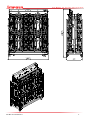
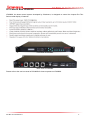
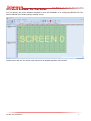
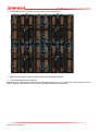
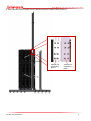
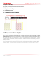
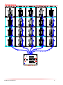
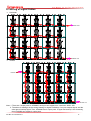
1
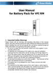
IMPOSA Pro Tour Series Installation Manual User Manual for Pro Tour Series Display Contents 1. Safety ............................................................................................................................................................................ 4 1.1 Guidelines ....................................................................................................................................................... 4 1.2 Safety Instructions ............................................................................................................................................ 4 2 Installation Requirements......................................................................................................................................... 5 2.1 Mechanical Requirements for the Pro Tour Series Rental Display ........................................................... 5 2.2 Electrical Requirements for the Pro Tour Series Rental Display ............................................................... 5 2.3 System Requirements for the Control Software ........................................................................................... 5 3. IMPOSA Pro Tour Series Cabinet............................................................................................................................. 6 3.1 Cabinet Structure .............................................................................................................................................. 6 3.2 Module Specification ........................................................................................................................................ 9 3.3 Control Box ...................................................................................................................................................... 10 4 Equipment and Accessories for IMPOSA Pro Tour Series Rental Display ..................................................... 11 4.1 Packing Box ..................................................................................................................................................... 11 4.2 Power Box........................................................................................................................................................ 14 4.3 Control Box LDU8000 .................................................................................................................................... 15 4.4 Cables .............................................................................................................................................................. 16 4.5 Control Software: Pro Tour Series ................................................................................................................ 17 5 Installation ................................................................................................................................................................ 18 5.1 Unpacking ........................................................................................................................................................ 18 5.2 Assembling between Cabinets ...................................................................................................................... 19 5.3 Hanging Installation ........................................................................................................................................ 25 5.3.1 Hanging Beam ........................................................................................................................................ 25 5.3.2 Splice of Two Hanging Beams .............................................................................................................. 28 5.3.3 Steps of Hanging Installation ..................................................................................................................... 29 5.4 Sitting Installation ............................................................................................................................................ 33 5.4.1 Components of the Bracket .................................................................................................................. 33 5.4.2 Steps of Sitting Installation .................................................................................................................... 34 6. System Wiring ........................................................................................................................................................... 44 6.1 System-Structural Diagram ........................................................................................................................... 44 6.2 Wiring between Power Supplies ................................................................................................................... 44 6.3 Wiring of Signal Cables ................................................................................................................................. 46 6.4 Wiring between Cabinets ............................................................................................................................... 47 7. Maintenance of the LED Display ............................................................................................................................ 49 8. Trouble Shooting ................................................................................................................................................... 50 8.1 The Indicators in the Back of the Cabinet ................................................................................................... 50 8.2 Fault Diagnosis ............................................................................................................................................... 51 8.3 How to Replace a Module? ........................................................................................................................... 53 8.4 How to Replace the Power Supply? ............................................................................................................ 55 8.5 How to Replace the Control Board? ............................................................................................................ 57 8.6 How to Replace the Baseboard?.................................................................................................................. 58 9 Appendix 1 Size ....................................................................................................................................................... 60 9.1 Size of a Pro Tour Series Module ................................................................................................................. 60 9.2 Size of a Pro Tour Series Cabinet ................................................................................................................ 60 9.3 Size of an LDU8000 ....................................................................................................................................... 61 9.4 Size of a PSU .................................................................................................................................................. 61 9.5 Size of a Flight Case ...................................................................................................................................... 62 9.6 Size of the Installation Brackets / Hanging Beams .................................................................................... 64 10 Appendix 2 Components ......................................................................................................................................... 65 10.1 Analysis of a Pro Tour Series Cabinet ....................................................................................................... 65 File NO. PTS-20130916-v1 2 User Manual for Pro Tour Series Display 10.2 Component List of a Pro Tour Series Cabinet .......................................................................................... 66 10.3 Cable List ....................................................................................................................................................... 70 10.4 Component List of Sitting Installation ........................................................................................................ 71 10.5 Component List of Hanging Beams ........................................................................................................... 72 File NO. PTS-20130916-v1 3 User Manual for Pro Tour Series Display 1. Safety Before installing an IMPOSA Pro Tour Series display, one is required to read this chapter carefully to obtain important information as to how to prevent personal injury and to protect the display from damage during installation. Overview Guidelines Safety instructions 1.1 Guidelines Before installing the display, make sure you have read the User’s Manual with full understanding. Installation must be performed by authorized and qualified technical personnel only. The installation site must be solid and without any chance of sinking, tumbling or falling. It must be at the same time free of over-heat, radiation, pollution, corrosion or gas release. Only use components provided by the Manufacturer or those approved or specified by the Manufacturer during installation of IMPOSA Pro Tour Series display’s. Do not modify and/or replicate any component or accessory without permit from the Manufacturer. Always follow all installation instructions. Please contact the Manufacture if any problem arises. 1.2 Safety Instructions Product care All parts must be fully protected and packed in good order during transportation, storage, etc. No external pressure shall be applied on them. No part of the product can come into contact with rain before or during installation. Keep them in dry and clean places. All parts must be prevented from being trampled or dropped. Follow all instructions while carrying or moving the parts. Otherwise the product can be subject to terminal damage. Installation Before installation, ensure that the supporting structure or frame has sufficient strength to hold the display firm and safe. For hoist installation, the operator must follow all instructions given in this User’s Manual, including where the hoist brackets should be located, that the crane used must come with sufficient capability to hoist the product, and that the operating ground must have the strength to sustain the crane, etc. In case any injury; please wear gloves when moving cabinet. Please be careful when you climb up the screen and perform maintenance or installation operations. All screws should be fixed tightly when screen is fixed on ground. Usage LEDs on the display cannot be pressured at any time. Otherwise they can be damaged permanently. Follow the steps mentioned in the User Manual while cleaning the front side of the display. Only a soft cloth or brush, neutral detergent and water are to be applied to the display. Power must be 100% off before dismantling any part for maintenance. File NO. PTS-20130916-v1 4 User Manual for Pro Tour Series Display 2 Installation Requirements This chapter covers requirements for installation, power supply and the control system of the IMPOSA Pro Tour Series display. Overview Mechanical requirements Electrical requirements System requirements 2.1 Mechanical Requirements Weight Make sure both the floor and the supporting structure can support five times of the weight of the entire display. One cabinet weighs approximately 23 Kg. The weight of supporting structure and the hanging beams should also be considered. Horizontal Plane For seat installation, the installation surface must be horizontal. Never install the display on a downward or upward slope. 2.2 Electrical Requirements Power Requirements Operates at AC 100-240V, 50~60Hz, 600W. Also provided is the power supply unit (PSU) for the display, which can meet this requirement. Please contact the Manufacturer for more information on the power requirements of Pro Tour Series display. Power System The power system of the display should be equipped with a circuit breaker and ground fault interrupter. This installation should be in accordance with the local regulations for power installation. 2.3 System Requirements for the Control Software Operation System Requirements PC System requirements: CPU Pentium IV or equivalent, 1GHz 512Mb DDR RAM Free hard disk space 300MB Resolution 1024x768 Windows XP Professional or Win7 Recommended PC System requirements: CPU Pentium IV, 2.4 GHz or above 2G DDR RAM Free hard disk space 100G Resolution 1920x1080 Win7 File NO. PTS-20130916-v1 5 User Manual for Pro Tour Series Display 3. IMPOSA Pro Tour Series Cabinet This chapter introduces the overall structure of the cabinet, module specifications and the control box. There are two kinds of Pro Tour Series rental cabinets, Pro Tour Series I and Pro Tour Series II. The cabinets of Pro Tour Series I can bend by ±15°on both sides to form a curved display. Pro Tour Series II is almost the same as Pro Tour Series I, except it cannot bend. Overview Pro Tour Series Cabinet Structure Pro Tour Series Module Specifications Control Box 3.1 Cabinet Structure Pro Tour Series Cabinet Structure: Structured by aluminum and steel, Pro Tour Series cabinets are rugged, robust and light weight. Each cabinet carries eight modules on the front. There are four positioning cones and three buckles on top of the cabinet. With two positioning cones and two buckles on the left, this design can realize precise positioning and fast installation and dismantling. There is a hidden handle on top of the cabinet which is for moving or carrying. There is a gauge for the measurement of bending on top of the cabinet, which is for fast positioning when clients install a curved display. Cabinet Drawings: D A B A B S A:Pro Tour Series Cabinet B:Power Box C:Control Box D:Pro Tour Series Module File NO. PTS-20130916-v1 C 6 User Manual for Pro Tour Series Display Components of the Cabinet: A B B A C A A G B H D H E G I D E I F A: Positioning Cones on the top B:Buckles on the top C:Handle D:Buckles on the sides E:Positioning Cones on the sides F:Positioning Port at the bottom G:Positioning Port on the sides H:Pedal Section. This can serve as a ladder when clients need to climb up the display from the back. This can also provide a place for screws when clients need to install more reinforcing ribs for big displays. I:Ports for Connection Poles in Seat Installation File NO. PTS-20130916-v1 7 User Manual for Pro Tour Series Display J L K J: Rotation Angle Gauge (Pro Tour Series II does not have this component.) K:Zero Positioning Pin (Pro Tour Series II does not have this component.) L:Angle Fixing Handle (Pro Tour Series II does not have this component.) File NO. PTS-20130916-v1 8 User Manual for Pro Tour Series Display 3.2 Module Specification Introduction to Pro Tour Series Modules The front of Pro Tour Series module consists of 3 in 1 SMDs and PC cover. There is a handle at the back of the module for easy installation and moving. Pro Tour Series Specifications Model Pixel Pitch Pixel Configuration VFI 5.33 5.33mm 3 in 1 SMD VFI 6.4 6.4mm 3 in 1 SMD VFI 8 VFI 10.6 8mm 10.6mm 3 in 1 3 in 1 SMD SMD Indoor/Outdoor VFO12.8 12.8mm 3 in 1 SMD Application Indoor Module Specification Module Resolution (HXW) Module Size (mm)(HXW) 72X36 60X30 48X24 384X192 36X18 30X15 144X144 120X120 96X96 768X768 72X72 60X60 Cabinet Specification Cabinet Resolution(H X W) Cabinet Size(mm)(HXW) Cabinet Weight (KG) Display Specification Max. Power Consumption per Cabinet (W) Brightness (cd/㎡) Directivity Angle IP Rating Grey Level Frame Frequency (Hz) Refresh Rate (Hz) Brightness Level File NO. PTS-20130916-v1 22 24 600 14Bit 2000 for Indoor / 6000 for Outdoor 140°/ 120° Front:IP65 Back:IP54 16Bit >60 ready 120/240 >1000 100 9 User Manual for Pro Tour Series Display 3.3 Control Box Control box is the core of a Pro Tour Series cabinet. It distributes the data from the LDU8000 to every module. Main Board Base Board File NO. PTS-20130916-v1 10 User Manual for Pro Tour Series Display 4 Equipment and Accessories for IMPOSA Pro Tour Series This chapter focuses on the external equipment and accessories for the IMPOSA Pro Tour Series. Overview Packing Box Power Box LDU8000 Control Box Cables Control Software Pro Tour Series 4.1 Packing Box There are 2 packing methods for IMPOSA Pro Tour Series. One is to use ordinary flight cases, and the other is to use customized flight cases to create more convenience for hanging installation. About Type 1 Flight Case Each Flight case is designed to contain 4 IMPOSA Pro Tour Series cabinets. The cabinets are protected against each other with a soft partition board in the middle. Flight Case Drawing The 4 sunken corners at the top of the flight case are for the purpose of piling the flight cases up at maximum 2 layers. Please refer to the following drawing: File NO. PTS-20130916-v1 11 User Manual for Pro Tour Series Display About Type 2 Flight Case Each Type 2 flight case can contain up to 8 cabinets. File NO. PTS-20130916-v1 12 User Manual for Pro Tour Series Display File NO. PTS-20130916-v1 13 User Manual for Pro Tour Series Display 4.2 Power Box Power boxes can be provided at clients' option. The manufacturer provides 2 types of power box. They are PSU25 and PSU40. Please see the below table for details: Model Power Output Channel PSU25 PSU40 25KW 40KW 9 15 1 2 3 4 5 6 7 8 9 20A 125V 200A 120/208V L1 L2 L3 N G PSU-25 Features of the Power Box: Of three-phase five-wire system; Equipped with short circuit device and manual switch for safe inspection and repair; c/w over-current, short circuit, over- and under-voltage protection; Designed with equal power distribution for all 3 phases, ensuring zero current leakage to the null line. File NO. PTS-20130916-v1 14 User Manual for Pro Tour Series Display 4.3 Control Box LDU8000 LDU8000, the latest control system developed by Chainzone, is designed to control the Imposa Pro Tour Series rental display. It features: Front View of LDU8000 Back View of LDU8000 Please refer to the user's manual of LDU8000 for how to operate on LDU8000. File NO. PTS-20130916-v1 15 User Manual for Pro Tour Series Display 4.4 Cables Signal Cable between Cabinets Power Cable between Cabinets Power cable from Cabinet to PSU Ethernet Cable from LDU8000 to Control PC File NO. PTS-20130916-v1 Signal Cable from Cabinet to LDU8000 DVI Cable to Graphic Card 16 User Manual for Pro Tour Series Display 4.5 Control Software: Pro Tour Series Pro Tour Series, the control software designed to work with LDU8000, is for configuring IMPOSA Pro Tour Series cabinets into a whole properly-working screen. Please refer to the Pro Tour Series user manual for its detailed operation and functions. File NO. PTS-20130916-v1 17 User Manual for Pro Tour Series Display 5 Installation This chapter tells how to unpack, how to assemble, to hang and to sit-mount Imposa Pro Tour Series cabinets Overview Unpacking Assembling between cabinets Hanging Sit-mounting 5.1 Unpacking Unpacking from Type 1 Flight Case 1. Open the 6 locks of Type 1 Flight Case File NO. PTS-20130916-v1 18 User Manual for Pro Tour Series Display 2. Take off the top cover of the flight case via the handles as shown below. Note: It requires at least 2 people to take off the cover. 3. Take out the IMPOSA Pro Tour Series cabinet. Note: It also requires 2 people to be able to take out the cabinet. The operator is advised to use gloves in order not to get hurt. 4. Repeat Step 3 till all cabinets in the flight case are taken out. 5.2 Assembling between Cabinets While assembling 2 neighboring cabinets, the operator must correctly direct the toggle clamp to the buckle on the other cabinet and then lock it downward. File NO. PTS-20130916-v1 19 User Manual for Pro Tour Series Display As shown below, when an upper cabinet is connected to the lower one, the upper cabinet must be placed properly into the toggle clamp at the top of the below cabinet. Then pull the clamp downward to have it locked: Make sure to lock these 3 toggle clamps tightly File NO. PTS-20130916-v1 20 User Manual for Pro Tour Series Display Combining the above 2 steps, one can easily get a screen put up: Make sure the toggle clamps as shown above are properly connected. Connection between bent cabinets Both sides of Pro Tour Series I cabinets can be freely bent by in or out 15°. So they can easily make up a curve screen. Please read below for how to do the connection between bent cabinets: File NO. PTS-20130916-v1 21 User Manual for Pro Tour Series Display 1. Bend the cabinet in the desired angle. Loosen off the angle-holding bracket. Pull down the 0°fixation pin and turn it by 90°. The steps are as shown below: Steps decomposed: File NO. PTS-20130916-v1 22 User Manual for Pro Tour Series Display 2. Turn both sides of the cabinet to the desired angle: 3. Press down the angle-holding bracket to prevent the sides of the cabinet from moving. (There is no need to return the 0° fixation pin to its original position.) File NO. PTS-20130916-v1 23 User Manual for Pro Tour Series Display 4. Turn all other cabinets to the same angle and connect them up with the toggle clamps: File NO. PTS-20130916-v1 24 User Manual for Pro Tour Series Display 5.3 Hanging Installation Hoisting assembly is a way to hang up the Cabinets, both curved cabinet and straight cabinet are available. 5.3.1 Hanging Beam There are three types of hanging beams: 280 hanging beam, 768 hanging beam, 1536 hanging beam. Because of the different sizes, each beam can connect different number of cabinets. But the ways of connection between each beam and cabinet are similar. 280 hanging beam 280 hanging beam is used to connect curved cabinet and waved cabinet. It provides suspension point for the cabinet. Each 280 hanging beam connects one cabinet. File NO. PTS-20130916-v1 25 User Manual for Pro Tour Series Display 768 Hanging Beam It is used to connect straight cabinet. Each 768 hanging beam connect one cabinet. 1536 Hanging Beam File NO. PTS-20130916-v1 26 User Manual for Pro Tour Series Display It is used to connect straight cabinet and each beam can connect two cabinet. File NO. PTS-20130916-v1 27 User Manual for Pro Tour Series Display 5.3.2 Splice of Two Hanging Beams Take 768 hanging beam for instance,(other types of hanging beam splice in the same way) On the front, two beams are spliced by a buckle, as the following figure: At the back, two beams are connected by stiffening plates File NO. PTS-20130916-v1 28 User Manual for Pro Tour Series Display 5.3.3 Steps of Hanging Installation Required Tools Crane Required parts Flight case 2 and Pro Tour Series cabinet Step 1: Remove the two side-guardrail of Flight case 2. Pull it down to unlock the latch Unlock the buckle Contrarotate to unlock it File NO. PTS-20130916-v1 29 User Manual for Pro Tour Series Display Step 2: Assemble the cabinets. Assemble the cabinets with hanging beams. Connect the cabinet and hanging beam according to the method described above. Step 3: Lift the assembled cabinets by crane, turn the flight case back and connect it with the cabinet in the opposite. File NO. PTS-20130916-v1 30 User Manual for Pro Tour Series Display Step 4: Connect other cabinets in this way. File NO. PTS-20130916-v1 31 User Manual for Pro Tour Series Display Step 5: Lift the display to a intended height. In case of slipping down, security steel chains must be add to the hanging beam. B B A >45° C A: The lifting chain of lifting hoist B: security steel chain C: U-shaped buckle Explanation: 1. The angle between security steel chains and hanging beam should be more than 45 degrees. 2. Security steel chains should be add to every hanging beam, and the stress point evenly distributed. File NO. PTS-20130916-v1 32 User Manual for Pro Tour Series Display 5.4 Sitting Installation This installation is to seat the cabinet on the ground through a bracket. It is only available to the straight cabinet. 5.4.1 Components of the Bracket Item 1 2 3 4 6 Name Pattern The bottom beam girder Vertical bar Singletree Connecting rod File NO. PTS-20130916-v1 33 User Manual for Pro Tour Series Display 7 8 9 100 angle aluminum Vertical bar connecting plate 1 Vertical bar connecting plate 2 5.4.2 Steps of Sitting Installation The example is the process of how to assemble 3 rows and 4 columns of cabinets. Tools Required 6mm hexagon screwdriver 10mm T type sleeve Parts Required All parts of the bracket Cabinets of Pro Tour Series: 12 File NO. PTS-20130916-v1 34 User Manual for Pro Tour Series Display Steps: 1. Use the botton beam, girder and 100 angle aluminum to form an “I” bracket and connect a cabinet. Bottom beam Girder Level ruler 100 angle aluminum Level ruler Note: The key point of this part is to adjust the level of the bottom. It can be achieved by moving the level rulers in the bottom beam and girders. Adjust the height of the girders’ stand using the T type sleeve File NO. PTS-20130916-v1 35 User Manual for Pro Tour Series Display After adjusting the level, connect the cabinet. 2. Assemble several “I”brackets, and install all cabinets of the first row. File NO. PTS-20130916-v1 36 User Manual for Pro Tour Series Display File NO. PTS-20130916-v1 37 User Manual for Pro Tour Series Display Note: Considering the influence of cabinets’ weight, when a row is finished, the level of the bottom should be readjusted. File NO. PTS-20130916-v1 38 User Manual for Pro Tour Series Display 3. Install the vertical bars on the second and fourth girders. Vertical bar Vertical bars connecting plate 2 4. Place the singletree between two vertical bars. The nuts on the end of the singletree can adjust the tightness of vertical bars. Singletree Embed the singletree into the vertical bars and contra rotate 90 degrees to enter the block. File NO. PTS-20130916-v1 39 User Manual for Pro Tour Series Display 5. Install the second raw of cabinets Install the second raw of cabinets 6、Install the connecting rod connecting rod File NO. PTS-20130916-v1 40 User Manual for Pro Tour Series Display The installation site of connecting rod: Connect one head of the rod to the elliptical holes on Mage cabinets File NO. PTS-20130916-v1 41 User Manual for Pro Tour Series Display 7. As the method described above, install the third row of cabinets. File NO. PTS-20130916-v1 42 User Manual for Pro Tour Series Display 8. More vertical bars are needed if more cabinets should be installed. Refer to step 3-7. Vertical bar connecting plate 2 File NO. PTS-20130916-v1 Vertical bar connecting plate 1 43 User Manual for Pro Tour Series Display 6. System Wiring This chapter covers the cabinet power wiring and signal wiring. Overview System-Structural Diagram Wiring between power supplies Wiring of signal cables Wiring between cabinets 6.1 System-Structural Diagram 6.2 Wiring between Power Supplies We can provide several types of Power Supply Unit, Customers can choose the right Power Supply Unit based on the size of their IMPOSA Pro Tour Series display, or we can also provide customized Power Supply Unit for special requirements. The output of each PSU port is 2.5KW which can support 4 pcs IMPOSA Pro Tour Series cabinets. The wiring of power cable can be horizontal, vertical, or U shape etc. Customers can choose a suitable way according to the actual situation. Note: If customers use the customized PSU, they need to consider how many cabinets each power supply cable can support. The maximum power consumption of each IMPOSA Pro Tour Series cabinet is 600W. File NO. PTS-20130916-v1 44 User Manual for Pro Tour Series Display POWER 1 2 3 MASTER 4 5 6 10 7 8 9 20A 125V Power box File NO. PTS-20130916-v1 45 User Manual for Pro Tour Series Display 6.3 Wiring of Signal Cables Horizontal LDU8000 Port LDU8000 Port Vertical LDU8000 Port LDU8000 Port Note: 1. There are 4 output ports on LDU8000, each port can support max. resolution 1920 x 340. 2. The above 2 drawings are the wiring drawing for signal hot backup. One port outputs signal, and the other port is backup signal. Thus, LDU8000 has 2 output ports. If signal hot backup is not necessary, then LDU8000 can support 4 output ports. File NO. PTS-20130916-v1 46 User Manual for Pro Tour Series Display 6.4 Wiring between Cabinets Please see the wiring between cabinets as follow: Signal cable File NO. PTS-20130916-v1 Power cable 47 User Manual for Pro Tour Series Display How to insert the signal cable and power cable: Aim at the groove and insert directly Spin the connector clockwise to the lock position after inserting correctly How to unplug the signal cable and power cable: Press the lock position and pull it out File NO. PTS-20130916-v1 Press the lock position and slide down a little, meanwhile, spin the connector anticlockwise and pull it out 48 User Manual for Pro Tour Series Display 7. Maintenance of the LED Display Why should we clean the IMPOSA Pro Tour Series modules? After a long time work outside, outdoor display will be exposed to various kinds of weather conditions, and can easily be smeared with grit, dust, smog etc., thus affecting the normal functioning of the IMPOSA Pro Tour Series module. It is therefore necessary to clean the surface of the LED Display regularly. Clean the LEDs and tile the masks of the IMPOSA Pro Tour Series module Regularly cleaning of the IMPOSA Pro Tour Series modules can reduce the overall brightness difference due to the dust. Necessary tools: Sprayer with neutral detergent Soft brush with long hair Garden hose with a spray nozzle Compressed air How to clean outdoor IMPOSA Pro Tour Series modules 1. Remove the power cables and signal cables. Seal the signal connector and power connector inside the control box; 2. Make sure the unused output port is sealed; Spraying the modules with neutral detergent in front from different angles and directions(Do not spray from the back of the module); Note: Do not use industrial lubricant. Only embedded, wearable, corrosion resistance and trackless materials or chemicals can be used. 3. Use a soft brush to clean all the rubbish and dirt on the LEDs and masks; Note: Do not use a hard brush. 4. Use clean water to thoroughly clean the redundant bubbles; Note: Do not put the whole IMPOSA Pro Tour Series cabinet totally or partly into the water or other liquid; 5. Repeat from step 3 until the modules are clean enough. 6. Use compressed air to dry up the display surface. How to clean indoor IMPOSA Pro Tour Series modules Unlike outdoor IMPOSA Pro Tour Series modules, indoor IMPOSA Pro Tour Series modules are non-watertight. You cannot clean the indoor modules with water. Compressed air should be used to clean the dust on the surface. File NO. PTS-20130916-v1 49 User Manual for Pro Tour Series Display 8. Trouble Shooting This chapter introduces some possible trouble symptoms and their remedial treatment to the IMPOSA Pro Tour Series display. Overview The indicators in the back of the cabinet Fault diagnosis How to replace a IMPOSA Pro Tour Series module How to replace a power supply How to replace a control board 8.1 The Indicators in the Back of the Cabinet The cabinet indicators include power indicator, signal indicator, and status indicator which can help to tell whether the power is failure or not, whether the control board work well or not, and whether the signal cable connects well. A A B C D Items A Name Power indicator B Signal indicator C Status indicator D Test button File NO. PTS-20130916-v1 Description Red light stands for power failure; No lights on stands for power ok. It has both left and right indicators. When blue light flashes at 1 second’s frequency, it shows data communicating. While when blue light flashes at 0.5 second’s frequency, it shows no data communicating. It has both left and right indicators. Red light shows the cabinet control board is starting; Green light shows that the cabinet works well; Yellow light(red and green lights are on at the same time) shows the control board failure. Press the test button for 5 seconds to enter the testing status. The cabinet will repeatedly display scanning lines, full red, full green, full blue, full white. Press the test button for another 5 seconds to return to the working status. 50 User Manual for Pro Tour Series Display 8.2 Fault Diagnosis Symptom Check items Solutions There is no power into the screen Power on DVI cable is not connected Connect the DVI cable The signal cable between LDU8000 and IMPOSA Pro Tour The whole screen is not displaying Series cabinet is not connected The control board indicator of IMPOSA Pro Tour Series cabinet flashes slowly Computer screen protection cabinet control board program is Upgrade the program Close the pixel calibration mode Make sure the power cable is well connected well connected Connect the cabinet signal cable The signal connector failure Replace left power box No power output Replace right power box Control box cable accessories failure Control board program File NO. PTS-20130916-v1 Replace the control board The power cable is not connected control box failure random contents Upgrade the LDU8000 program Power on the control card at the bottom of the The cabinet keeps showing screen There is no power into the cabinet The cabinet signal cable is not displaying computer not correct brightness data not the All the IMPOSA Pro Tour Series The control board doesn’t have is Cancel Show display content cabinet control board failure cabinet cable or replace the network cable The displaying area is all black The first IMPOSA Pro Tour Series The Check the connector of network protection system and hibernation match showing random contents them system The LDU8000 program does not The whole screen keeps Connect the signal cable between correct Control board failure is not Replace Replace Upgrade the program Replace the control board 51 Control board failure User Manual for Pro Tour Series Display Replace the control board LED module failure Replace The LED module is not The D-shape connector is not Make sure the D-shape connector displaying or keeps showing connected well is connected well random contents The control board current gain is not correct One unit shows a different color Some LEDs are dead File NO. PTS-20130916-v1 The control board does not have brightness data Re-write the current gain data or replace the control board with current gain data Re-write the brightness data control board failure Replace the control board The LEDs are broken Replace the LED module 52 User Manual for Pro Tour Series Display 8.3 How to Replace a Module Necessary tools: Cross head screw driver Necessary components: IMPOSA Pro Tour Series module Process to replace a module 1.Remove the PLUS D-shape connector on the module as follow: Loose screws of D shape connector and take the D shape connector out. File NO. PTS-20130916-v1 53 User Manual for Pro Tour Series Display 2. Unfasten the screws on the back of the module as follow: Unfasten the 8 screws on the module 3. Pull the module out 4. Install the module on the contrary steps. File NO. PTS-20130916-v1 54 User Manual for Pro Tour Series Display 8.4 How to Replace the Power Supply Necessary tools: Cross head screw driver Necessary components: A power supply Process to replace a power supply 1. Unfasten the screws on the side of the power supply box Loose screws on the side of power box, 4 pcs in total 2.Pull out the power supply box Pull out the power supply box by some force File NO. PTS-20130916-v1 55 User Manual for Pro Tour Series Display 3. Unfasten the screws on the bottom of the power supply box and remove the bottom part (The power supply will be pull out as well) 4. Install the power supply on the contrary steps. File NO. PTS-20130916-v1 56 User Manual for Pro Tour Series Display 8.5 How to Replace the Control Board Necessary tools Cross head screw driver Necessary components A control board Process to replace a control board 1. Unfasten the 3 screws on the control box door, and then open the door 2 .Unfasten the screw on the control board by hand, and pull out the control board 3. Install the control board on the contrary steps. File NO. PTS-20130916-v1 57 User Manual for Pro Tour Series Display 8.6 How to Replace the Baseboard Necessary tools Cross head screw driver Necessary components a baseboard It’s a little complicated to replace the baseboard, please see the specific steps as follow: 1.First, remove the power supply boxes on both sides of the control box. You can refer to the above steps of removing the power supply box 2.Remove the control board refer to the above steps. 3.Remove the power connectors on both sides of the control box. File NO. PTS-20130916-v1 58 User Manual for Pro Tour Series Display Unfasten the 4 screws as follow 4.Unfasten all the screw around the baseboard and pull out the baseboard File NO. PTS-20130916-v1 59 User Manual for Pro Tour Series Display 9 Appendix 1 Size 9.1 Size of a Pro Tour Series Module 173.5 92.5 104 192 192 104 188 20 15 33 246 384 802 768 768 802 9.2 Size of a Pro Tour Series Cabinet 161 161 96 768 File NO. PTS-20130916-v1 60 User Manual for Pro Tour Series Display 9.3 Size of an LDU8000 Temp Power Genlock DVI Ethernet + OUTDOOR - INDOOR STATE Black Freeze Test Info 44 Port 1 Port 2 Port 3 Port 4 Artnet F1 LDU8000 482 380 350 432 9.4 Size of a PSU POWER 1 2 3 MASTER 4 5 6 10 7 8 9 20A 125V 1 2 3 4 5 6 7 8 9 20A 125V 200A 120/208V L1 File NO. PTS-20130916-v1 L2 L3 N G 61 User Manual for Pro Tour Series Display 9.5 Size of a Flight Case Flight case 1 840 900 900 830 840 830 File NO. PTS-20130916-v1 62 User Manual for Pro Tour Series Display 655 650 660 1621 1621 File NO. PTS-20130916-v1 63 1676 1463 1510 Flight case 2 1676 User Manual for Pro Tour Series Display 9.6 Size of the Installation Brackets / Hanging Beams Hanging beam L=280mm 176 172 39 40 37 140 210 117 172.5 140 97 280 Hanging beam L=768mm 384 57 768 192 192 117 193 172.5 210 192 97 650 Hanging beam L=1536mm 384 768 57 1536 117 173 59 File NO. PTS-20130916-v1 650 118 650 97 64 193 384 210 384 User Manual for Pro Tour Series Display 10 Appendix 2 Components 10.1 Analysis of a Pro Tour Series Cabinet File NO. PTS-20130916-v1 65 User Manual for Pro Tour Series Display 10.2 Component List of a Pro Tour Series Cabinet item Part number Name 1 880-2006 Top (frame) 2 880-2021 Top positioning pin 2 3 880-2022 Top positioning pin 1 4 880-2001 quick clamp L=93mm 5 880-3006 341_r handle 880-3001 Spring pin 1 (right zero positioning pin) 880-3002 Spring pin 2 (left positioning pin) 880-3003 Cam handle base (left pressure head ) 6 7 8 File NO. PTS-20130916-v1 Pattern Note 66 User Manual for Pro Tour Series Display 9 880-3004 Cam handle base (right pressure head ) 10 880-2037 V-shape keyway 11 880-2059 12 880-2040 13 880-3005 14 880-7102 Keyboard plate 15 880-7101 Main controller 40334 positioning buckle ¢6 lifting handle Control box 880-6001 880-6002 16 880-60xx 880-6003 Left tile 880-6004 880-6005 File NO. PTS-20130916-v1 5.33mm pitch indoor 6.4mm pitch outdoor 8mm pitch outdoor 10.6mm pitch outdoor 12mm pitch outdoor 67 User Manual for Pro Tour Series Display 17 880-2020 Sided positioning pin 18 880-2002 Quick clamp L=87mm 19 880-7201 20 880-7301 21 880-2016 Corner connector 22 880-2529 Plate seal gasket 23 880-7202 Right power supply 24 880-2019 Small hook Left power supply Plus D shape connector File NO. PTS-20130916-v1 68 User Manual for Pro Tour Series Display 880-6101 880-6102 25 880-61xx Right tile 880-6103 880-6104 880-6105 26 880-3004 27 880-2007 Bottom (frame) 28 880-2061 Control box seal gasket 29 880-7103 Control box bottom board 30 880-7302 Control box cable accessories 31 880-7303 Keyboard signal cable 5.33mm pitch indoor 6.4mm pitch outdoor 8mm pitch outdoor 10.6mm pitch outdoor 12mm pitch outdoor V shape pin accessories File NO. PTS-20130916-v1 69 User Manual for Pro Tour Series Display 10.3 Cable List Item Part Number Name 1 880-7311 Power cable L=1.2M 2 880-7312 Power cable L=10M 3 880-7313 Signal cable L=1.2M 4 880-7314 Signal cable L=10M 5 880-7315 Ethernet cable L=10M 6 880-7316 DVI cable File NO. PTS-20130916-v1 Pattern Note 70 User Manual for Pro Tour Series Display 10.4 Component List of Sitting Installation Item Number Name 1 880-3531 Bottom Horizontal beam 2 880-3532 Carling 3 880-3533 Vertical beam 4 880-2276 Needling 5 880-2203 Needling spindle 6 880-3104 Connecting rod 7 880-2114 Aluminum corner supporter 8 880-2185 Installation nut strip File NO. PTS-20130916-v1 Pattern Note 71 User Manual for Pro Tour Series Display 9 10 880-2244 Vertical beam connecting board 1 880-2254 Vertical beam connecting board 2 10.5 Component List of Hanging Beams Item Part Number Name 1 880-3536 Hanging beam L=280mm 2 880-3546 Hanging beam L=768mm 3 880-3556 Hanging beam L=1536mm File NO. PTS-20130916-v1 Pattern Note 72