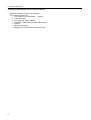
1
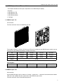
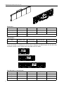
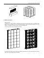
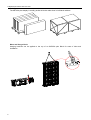
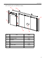
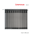
IMPOSA plus Series User’s Manual
CHAINZONE TECHNOLOGY (FOSHAN) CO.,LTD.
Table of Contents
Table of Contents
1. Safety
1.1 Guidelines
1.2 Safety instructions
2. IMPOSA plus Series Tiles and Units
2.1 IMPOSA plus Tile
2.2 IMPOSA plus Unit
2.3 IMPOSA plus Block
2.4 IMPOSA plus display
3.
3.1
3.2
3.3
Installation requirements
Mechanical requirements
Electrical requirements
System requirements for the Control software
4.
4.1
4.2
4.3
4.4
4.5
4.6
4.7
4.8
Components of an IMPOSA plus display
IMPOSA plus Unit and Block
Mechanical Components
Power Supply Unit (PSU)
Logic Distribution Unit (LDU)
Video Processing Unit (VPU)
Cables
Control software
Others
5. Installation
5.1 Preparing the supporting structure
5.2 Mounting a typical IMPOSA plus display
5.2.1 Preparing the Block
5.2.2 Mounting the Blocks
5.2.3 Fixing other structural components
5.3 Mounting a large IMPOSA plus display
5.3.1 Mounting empty Blocks
5.3.2 Mounting the Units
5.3.3 Fixing other structural components
5.4 Mounting a small IMPOSA plus display
5.4.1 Assembling the IMPOSA plus display
5.4.2 Mounting the small IMPOSA plus display
5.5 Mounting a front serviced IMPOSA plus display
5.5.1 Preparing the supporting structure
5.5.2 Preparing the Block
5.5.3 Mounting the Blocks
5.5.4 Fixing other structural components
5.6 Typical mounting of a block structure
1
Table of Contents
6. Cabling an IMPOSA plus display
6.1 Cabling between Units
6.2 System cabling
6.2.1 Cabling an on-line IMPOSA plus display
6.2.2 Cabling an off-line IMPOSA plus display
6.3 Pixel limitations
6.3.1 Limitation of signal connection
6.3.2 Limitation of power connection
7. Maintenance
7.1 Firmware update
7.1.1 LDU firmware update
7.1.2 Updating the display unit controller firmware
7.2 Replacing a Tile of an IMPOSA plus display
7.3 Replacing a Tile of a front serviced IMPOSA plus display
7.4 Replacing a power supply of the display unit
7.5 Replacing a display unit control board
7.6 Replacing an LDU control board
7.7 Cleaning Tiles masks
8. Trouble shooting
9. Specifications
9.1 IMPOSA plus display VFO series specifications
9.2 Dimensions of an IMPOSA plus display
9.3 Weights of IMPOSA plus display parts
10. Part Numbers of IMPOSA display parts
2
1.Safety
1. Safety
Before installing an IMPOSA plus display, one is required to read this chapter carefully to obtain
important information as to how to prevent personal injury and to protect the display from damage
during installation.
Overview
Guidelines
Safety instructions
1.1 Guidelines
Before installing the display, make sure you have read the User’s Manual with full understanding.
Installation must be performed by authorized and qualified technical personnel only.
The installation site must be solid and without any chance of sinking, tumbling or falling. It must be at
the same time free of over-heat, radiation, pollution, corrosion or gas release.
Only use components provided by the Manufacturer or those approved or specified by the
Manufacturer during installation of IMPOSA plus series displays.
Do not modify and/or replicate any component or accessory without permit from the Manufacturer.
Always follow all installation instructions. Please contact the Manufacture if any problem arises.
Special attention should be paid to all “CAUTION” and “TIPS” mentioned in this User’s Manual which
respectively intends:
CAUTION: to draw operators’ attention to an important instruction or to remind them of what
might happen.
TIPS: to give advice on how to perform an operation better.
1.2 Safety instructions
Product care
All parts must be fully protected and packed in good order during transportation, storage, etc. No
external pressure shall be applied on them.
No part of the product can come into contact with rain before or during installation. Keep them in dry
and clean places.
All parts must be prevented from being trampled, stroke or dropped. Follow all instructions while
carrying or moving the parts. Otherwise the product can be subject to terminal damage.
Installation
Before installation, ensure that the supporting structure or frame has sufficient strength to hold the
display firm and safe.
For hoist installation, the operator must follow all instructions given in this User’s Manual, including
where the hoist brackets should be located, that the crane used must come with sufficient capability
to hoist the product, and that the operating ground must have the strength to sustain the crane, etc.
3
1.Safety
Most components of the product are heavy. Therefore high attention should be paid to personnel
safety during installation.
All connection bolts must be fastened firmly and securely.
Power
An IMPOSA plus display is to be powered by a 3-phase power with 5 lines. That is, it must come with
an independent neutral line and an independent ground line.
Provide the power and power supply circuits in accordance with the power consumption of the
display. All circuits must come with protection tubes and confirm with the local electrical safety
standards.
The LDU and PSU must be installed near the display. Cables from the LDU and PSU to the display
cannot be stretched or impaired. Power distribution from the PSU to the display cannot exceed what
is required by this User’s Manual.
The input voltage of an IMPOSA plus display can be set at 120VAC or 220VAC. But ensure to set it
right before power connection.
Do not attempt to fix an impaired cable. Replace it with a new one.
A big current is produced the moment a display is powered on. Therefore an air breaker that can
sustain big currents should be used as the master power switch.
Grounding
IMPOSA plus displays must be grounded with an INDEPENDENT ground wire.
Displays to be installed independently from any architectural structure must be equipped with an
independent ground wire and, if necessary, a lightning rod. The down lead of the lightning rod should
be insulated with the frame of the display. Set the earth electrode of the lightning rod and that of the
ground wire away from each other.
Usage
LEDs on the display cannot be pressured at any time. Otherwise they can be damaged for good.
4
Follow the steps mentioned in this User’s Manual while cleaning the front side of the display. Only
soft clothing or brush, neutral detergent and water are to be applied to the display.
Power must be cut off before dismantling any part for maintenance.
2.IMPOSA plus Series Tiles and Units
2. IMPOSA plus Series Tiles and Units
This chapter introduces the major components of an IMPOSA plus display.
Overview
IMPOSA plus Tile
IMPOSA plus Unit
IMPOSA plus Block
Package
2.1 IMPOSA plus Tile
Tile overview
The front and back view of an IMPOSA plus tile
The models VFO13.3, VFO16, VFO 20 and VFO 26.7 included in the IMPOSA plus series use the
same tile but with different resolutions. Please see below:
Tile
VFO13.3
VFO16
VFO 20
VFO 26.7
Pixel pitch
13.3mm
16mm
20mm
26.7mm
Resolution
24X24
20X20
16X16
12X12
Weight
2.7kg
Part Numbers
Tile
VFO13.3 Tile
VFO16 Tile
VFO 20 Tile
VFO 26.7 Tile
Part Number
380-013001
380-016001
380-020001
380-026001
2.2 IMPOSA plus Unit
Unit overview
A typical IMPOSA plus Unit is made up of 4 tiles, 1 power box,2 structure bars and several cables.
This unit is the smallest function control unit of the IMPOSA plus series.
The front and back view of the IMPOSA plus tile:
5
2.IMPOSA plus Series Tiles and Units
Parameters
Unit
VFO13.3
VFO16
VFO 20
VFO 26.7
Pixel pitch
13.3mm
16mm
20mm
26.7mm
Resolution
96X24
80X20
64X16
48X12
Weight
18.5kg
18kg
Part Numbers
Unit
VFO13.3 Unit
VFO16 Unit
VFO 20 Unit
VFO 26.7 Unit
Partnumber
381-013001
381-016001
381-020001
381-026001
To be more flexible in combining into various sizes of displays, the IMPOSA plus unit can also come
in different quantity of tiles. Please refer to the table below for details:
Pixel Reslution of special Units
6
VFO13.3
VFO16
VFO 20
VFO 26.7
2 Tiles
48x24
40x20
32x16
24x12
3Tiles
72x24
60x20
48x16
36x12
5Tiles
120x24
100x20
80x16
60x12
2.IMPOSA plus Series Tiles and Units
Packages
2.3 IMPOSA plus Block
Block overview
Composed of a certain number of IMPOSA plus units and the structural frame, the IMPOSA plus
Block is the big installation unit for the IMPOSA plus display. When the height of a display is no more
than 5m, the height of the Block equals to that of the display itself.
The front and back view of an IMPOSA plus block.
An IMPOSA plus Block can be made with different specifications of units mentioned above, so that
blocks with more flexible sizes are available.
7
2.IMPOSA plus Series Tiles and Units
Package
The IMPOSA plus display is usually packed in blocks rather than in individual cabinets.
Move and Hang a block
Hanging brackets can be applied to the top of an IMPOSA plus Block for ease of hoist and
installation.
8
2.IMPOSA plus Series Tiles and Units
Hang the Block from aside
CAUTION: While hoisting a display, steps shall be strictly followed as below so as not to damage
the LEDs.
9
2.IMPOSA plus Series Tiles and Units
2.4 IMPOSA plus display
IMPOSA plus display overview
Featuring simple structure and quick, easy installation, the IMPOSA plus display usually consists of a
certain number of IMPOSA plus blocks in structural frames.
View of an IMPOSA plus display
Part Numbers
Parts
Part Numbers
1
Beam
380-1001XX
2
Side cover
380-1002XX
3
Hook
380-100401
4
Eyebolt
380-100402
The size of an IMPOSA plus display depends on its length and height, both of which are an integral
multiple of 320mm in the IMPOSA plus design. Therefore various sizes are available for clients’
option.
An IMPOSA plus display is composed of a certain number of standard blocks and one extra block
with a special length. This special block is usually placed at the right side of the screen looked from
the back.
View of a P20mm IMPOSA plus display with the resolution of 240X96, sized 4800mmX1920mm:
10
2.IMPOSA plus Series Tiles and Units
11
3.Installation requirments
3. Installation requirements
This chapter covers requirements for installation, power supply and the control system of an IMPOSA
plus display.
Overview
Mechanical requirements
Electrical requirements
System requirements
3.1 Mechanical requirements
An IMPOSA plus display comes with its own structural frames. Besides, it requires a strong and
reliable supporting frame at the back to hold the display firm. Wherever this supporting frame is to be
installed, on the ground, onto the pole, in front of an object or on the top of a building, attention should
be paid to the following few points:
1.
2.
3.
4.
The display should be installed in a place that allows a clear and complete view of the display.
The supporting frame has to be strong enough to prevent the display from tumbling.
Make sure the mounting surface of the supporting frame is at the same plane.
The installation site must have the strength to withstand the total weight of the display plus its
structural frames.
5. Do not use the display in extreme environments. Take the ambient temperature, dust and
ventilation, esp. that at the back of the display, into consideration while choosing an installation site.
The erection plane of a typical IMOSA plus display
12
3.Installation requirements
A typical supporting frame for the IMOSA plus display
3.2 Electrical requirements
Power requirements
An IMPOSA plus Block works on AC 200-240V, 50~60Hz. Each block has an independent power supply
circuit and can thus be powered by electricity from different phases.
IMPOSA plus displays are to be powered by 3-phase power supply circuits which include a hot, neutral
and ground wire. The 3-phase power distributes power to each block on an average level.
The IMPOSA plus block can also be powered by AC100-125V, 50~60Hz power supplies. But it’s alike
recommended to power the whole display with a 3-phase power c/w 5 lines. In some circumstances a
single-phase power can be used as well.
A PSU (power supply unit) is used to control power supplied to the IMPOSA plus display.
Grounding
Whether there is a ground wire in its power supply circuit or not, an IMPOSA plus display must be
grounded at the installation site. Good grounding will enable the display to work properly and can
prevent it from being disturbed by surge.
13
3.Installation requirments
3.3 System requirements for the Control software
When the Windows System is in question:
PC System requirements:
CPU Pentium IV or equivalent, 2.4GHz
1 GB DDR RAM
Free hard disk space 300MB
Resolution 1280x1024 with 32M video memory
DVI port
Ethernet connection
Windows XP Professional or Windows Vista
14
4.Components of an IMPOSA plus display
4. Components of an IMPOSA plus display
This chapter continues to introduce components that complete an IMPOSA plus display.
Overview
IMPOSA plus Unit and Block
Mechanical Components
Power Supply Unit (PSU)
Logic Distribution Unit (LDU)
Video Processor Unit (VPU)
Cables
Control software
Others
4.1 IMPOSA plus Unit and Block
Introduction to the IMPOSA plus Unit
The IMPOSA plus Unit is the basic display unit of an IMPOSA plus display. The unit is usually
composed of 4 tiles, 1 power box, some structural bars and 4 cables. Inside the power box are a switch
power supply for the 4 tiles, the control board QS5246 and in and out power and data connectors.
Parts of the IMPOSA plus Unit
15
4.Components of an IMPOSA plus display
Parts and Part Numbers
Parts
Part Numbers
Remark
1
Tile
380-016001
16mm
2
Top beam
380-100403
3
Bottom beam
380-100404
Cable left cover
380-100501
Cable center cover
380-100502
Cable right cover
380-100503
5
Power supply
380-200101
S-320-5
6
Control board
380-200201
5242
7
Power box
380-100501
8
Screw(M4X50)
9
Signal connector left
380-300001
Signal connector right
380-300002
Screw(M6X12)
M6X12
Fan
380-200301
4
10
M4X50
5V 60X60X20
Introduction to the IMPOSA plus Block
As the core component that makes up of an IMPOSA plus display, the IMPOSA plus Block helps make
the assembling and installation of the display very simple and easy.
16
4.Components of an IMPOSA plus display
Parts of an IMPOSA plus Block
Parts and Part Numbers
Parts
Part Numbers
Remark
1
Unit(1280mmx320mm)
381-016001
16mm
2
Block plate
380-100405
3
Connection bracket
380-100406
4
Aluminum frame
380-1003XX
5
Countersunk head screws(M6X40)
6
Hook
7
Countersunk head screws(M6X40)
8
Supporting beam
9
Screw(M6X12)
M6X40
380-100401
M6X40
380-100407
M6X12
4.2 Mechanical Components
Besides the IMPOSA plus Block, an IMPOSA plus display also comes with structural components
including a top beam, a bottom beam, side covers and eyebolts, etc.
A top beam together with a bottom beam forms the main structural component that integrates all the
Blocks into a complete display.
17
4.Components of an IMPOSA plus display
The side covers are more of a decorative purpose. They are used to make the display look complete as
a quadrangle.
Eyebolts are used to hoist a display. They can be removed after the display has been installed in place.
Parts and Part Numbers
Parts
18
Part Numbers
Remark
1
Block
2
Top Beam
3
Countersunk head screws(M6X40)
M6X40
4
Screw(M12X35)
M12X35
5
Hook
380-100401
6
Eye rings
380-100408
7
Side cover
380-1002XX
8
Screw(M12X45)
9
Bottom beam
10
Hook lock
11
Hang plate
380-1001XX
Remove before fix top beam
M12X45
380-1001XX
4.Components of an IMPOSA plus display
4.3 Power Supply Unit (PSU)
The PSU, short for Power Supply Unit, is the power control center for an IMPOSA plus display. Power to
each Block can be directly connected to the PSU in order. Each channel on the PSU connects one
Block.
A PSU is inbuilt with a surge protector so as to prevent the display from being disturbed by lighting.
The PSU can also be connected with the LDU to realize remote display on/off control.
Parts and Part Numbers
Parts
Part Numbers
Remark
PSU-10KW
381-100110
120V
PSU-25KW
381-100125
120V
PSU-40KW
381-100140
120V
4.4 Logic Distribution Unit (LDU)
The LDU is the central controller for an IMPOSA plus display. It mainly includes the control board
QS5800 or QS5003.
19
4.Components of an IMPOSA plus display
Parts and Part Numbers
Parts
Part Numbers
Remark
1
LDU3000
381-100201
2
Control board (QS5800)
380-200202
QS5800
3
Power supply (5V)
380-200102
5V
4
Fan
380-200302
4.5 Video Processing Unit (VPU)
The VPU, short for Video Processing Unit, is the video and DVI sync processor in the IMPOSA
synchronous control system. It is compatible with various video signal inputs as well as the DVI signal
input. These signals are then transmitted to the LDU via an optic fiber and shown on the display.
Instrutuion
Parts
1
Power switch
2
LCD screen
3
Menu
4
Shortcut key to other Video Sources
5
Shortcut key to DVI Input
4.6 Cables
Signal cable between LDU and Blocks
20
Power cable between PSU and Blocks
4.Components of an IMPOSA plus display
DVI cable
Fiber cable
Network cable
USB cable
4.7 Control software
The series of control software developed by Chainzone itself are meant for system setting, test and
display control of an IMPOSA plus display.
TIPS: Please refer to the user’s manual of each control software for more information about their
functions and use guidance.
IMPOSA Tool
IMPOSA Tool is the tool software for the LDU to set up, configure, manage and test the display.
21
4.Components of an IMPOSA plus display
Sigma 3000
Sigma 3000 is a powerful control software for an offline system. It can be used to set up, configure the
display as well as control, manage, test and record what is shown offline on the display.
LED Net
LED Net is another functional offline control software that controls via the Web. It’s embedded in the
control board QS5800 and is meant for use on this board only.
22
4.Components of an IMPOSA plus display
IMPOSA play
IMPOSA play is the sync control software for an IMPOSA plus display. It’s used to control synchronous
display of video files on the display as well as for system setup.
VPU 3400
VPU 3400 is the setup and control software for the VPU. It’s used to manage and control the
synchronous display of various videos inputs on the display and as always, system setup.
23
4.Components of an IMPOSA plus display
4.8 Others
There are some other accessories that may be required whether for the offline or synchronous system.
Clients can provide such accessories on their own according to actual application or to their
preferences.
DSL Modem
A DSL Modem is required for an offline
IMPOSA plus display that is to be
controlled remotely or via the Internet.
Users can easily get this item from the
market by themselves. The user also
needs to apply for the DSL route at the
local telecom bureau.
Wireless Access Point
However, when the offline IMPOSA plus
display is not far away from the control
center, the user can simply use a
wireless AP or wireless Router to
integrate the display into the Wi-Fi
network. The display shall then be able
to communication with the computer in
the network. If the display can even be
seen in the straight direction, the use is
advised to use a directed wireless AP
instead whose com distance can go up
to 1km.
Router
Besides the display itself, some other
accessories c/w the display, say the
Network Camera, also require access to
network. Therefore a network port,
usually a Router, should be built in the
display.
If the display is a double-sided one
embodied in 2 cabinets, the Router shall
have to integrate both sides into the
communication network.
Of course, the user can directly use a
wireless AP that comes with the Router
function as well.
Network Camera
Most displays that are controlled
remotely are equipped with a Network
Camera in front of the top of the display.
By doing so, the user can watch over the
running condition as well as what’s
being shown on the display in real time.
A camera that can live up to such an
application must be waterproof and
come with wide-angle lens. As far as we
know, the MOBOTIX M22M can be a
good choice.
24
4.Components of an IMPOSA plus display
Others
To complete the control system, a computer installed with various video or picture tailoring or editing
software is also required.
If the synchronous system is in question, extra video devices say a Camera, a Record disc, etc. are
requires as well.
All the accessories mentioned above are to be provided by the user on their own based on actual
applications.
An IMPOSA plus display with offline system
Ethernet
RS232
USB
RS485/RS232
3G/
GPRS
Note
1
Display
2
Brightness/temperature/humidity sensor
3
LDU
4
PSU
5
USBRS485/RS232 Convertor
6
3G Modem/GPRS Modem
7
PC
8
3GModem/GPRS Modem
25
4.Components of an IMPOSA plus display
An IMPOSA plus display with synchronous system
CVBS
SDI
HDMI
Optic Fiber
DVI
Net
Power supply
Note
26
1
Display
2
LDU
3
PSU
4
PC
5
VPU
6
Camera
7
Player
8
Cable TV
5.Installation
5. Installation
This chapter describes the various installation methods of an IMPOSA plus display.
Overview
Preparing the supporting structure
Mounting an IMPOSA plus display
Mounting a front serviced IMPOSA plus display
typical mounting of a Block
5.1 Preparing the supporting structure
There are hooks on each Block of an IMPOSA plus display. These hooks are to be connected with the
supporting structure.
Typical installation of an IMPOSA plus display
The connection positions on the supporting structure must correspond to the hooks on the IMPOSA
plus display. In a standard IMPOSA plus display, the distance between 2 neighboring hooks in the
vertical direction is 320mm, equaling to the height of an IMPOSA plus Unit. The quantity of hooks in
the vertical direction is thus correlated to the height of a display, or, in other words, to the quantity of
units in the height of a display.
27
5.Installation
Display Height
(H)
Unit Qty. in Vertical
Hook Qty.
Distance of Hooks
2110
6
2
1280
3390
10
3
4670
14
4
5850
18
5
Chainzone provides a special moudel tool for clients to easily locate the mounting position where
hooks connect with the beams.
When building or rebuilding the supporting structure, it’s of great importance to ensure a leveled
surface between the beams.
CAUTION: Before installing a display onto an existent supporting structure (for instance, to replace
the original billboard with an IMPOSA plus display), the client is advised to discuss with
Chainzone or its agent before production to make sure hooks on the Blocks would
match connection positions on the existent supporting structure.
The client needs to make sure the existent supporting structure has the strength to sustain the weight
of the display before he sets to replace the original billboard with an IMPOSA plus display. If not, the
client may need to enhance the structural strength of the supporting structure. Positions that connect
with the hooks of the display need to be strengthened as well.
The following example shows how to reconstruct an existing billboard supporting structure for an
IMPOSA plus display:
28
5.Installation
5.2 Mounting a typical IMPOSA plus display
The typical IMPOSA plus display refers to a display that can be packed and shipped in blocks with the
height of the block between 8 and 16. Such a display can be installed in a simplest way as shown
below:
Necessary Conditions
The display can be packed and shipped in Blocks.
A crane can be applied in the installation site.
Necessary tools
A crane
19mm open-end wrench
19mm box-end wrench
A Drill and 13mm drill bits
5.2.1
Preparing the Block
Remove the blocks from their package.
29
5.Installation
CAUTION: A block can be very heavy. Therefore one needs to be extremely careful while removing
the block. Unpacking has to be done in strict order as shown above. The LEDs cannot
touch the ground directly or be pressured. Otherwise the LEDs can be terminally
damaged.
Operations shown below are strictly forbidden:
To mount hooks onto a block
旧的 PLUS 安装钩示意图
30
5.Installation
新的 PLUS 钩安装示意图:
滑块
M12X30 bolt
Hook
新旧的区别:旧的 PLUS 需要钻孔,螺栓穿过型材。新的 PLUS 型材中有滑块,螺栓通过滑块来上紧,不需
要钻孔。
Remove the Block and lay it on its side. Fasten eyebolts onto the top of thd block and put it down.
Hoist the Block.
5.2.2
Mounting the Blocks
Before mounting blocks, one must make sure:
The Blocks are ready to be installed and LEDs on them are intact.
The supporting structure is in place, esp. the beams.
The crane has the strength to hoist the Blocks and all operations at the installation site will be
harmless.
Installation shall start from the middle. Make out the position for the middle block of a display and
install this first block onto the supporting structure. Make sure all hooks on the block connect well
with the beams.
31
5.Installation
Then install the second middle block. After mounting it in position, use M12X80 bolts and nuts to
connect the 2 installed blocks together. While connecting, make sure the 2 blocks are leveled so that
pixels will be in the same level, too.
Install other blocks at both sides in order.
The following example shows how to mount IMPOSA plus blocks:
There is a sequence number on each block. Looked from the back, this number increases from right
to left. Blocks shall be arranged in accordance with the sequence numbers while being installed.
The special block, if any, is to be placed at the last, i.e. at the left end if looked from the back.
32
5.Installation
5.2.3
Fixing other structural components
After the blocks are installed, structural components shall be added to the display.
Mounting the top Beam and the bottom beam
Fasten the top and bottom beam with the blocks with M12X35 bolts.
33
5.Installation
If the length of the display goes over 6m, the beam shall come in 2 sections which will be connected
to each other while being installed.
Mounting the side covers
Use M12X80 bolts to fix the side covers at both sides of the display.
34
5.Installation
Mounting the Hooks protection chuck plate
A protection chuck plate is used to lock the hook, so that the block connected to the hook won’t drop
off the beams by any chance and cause damage. It’s required that one hook at the top and one at
the bottom of a Block must be mounted with a protection chuck plate.
Choosing a location for the LDU and PSU
Where to place the LDU and PSU depends on the length of cables connecting from the bottom of
Blocks to the LDU and PSU. Therefore they are usually laid in the middle line of a place that is close
to the bottom of Blocks at the back of the display.
35
5.Installation
36
5.Installation
5.3 Mounting a large IMPOSA plus display
A large IMPOSA plus display refers to a display that goes over 6m in height and has to be shipped in
separate Units and block structures due to its excessive height and weight.
Necessary condition
The display has to be shipped in separate Units and block structures due to over height and
weight.
Necessary tools
19mm open-end wrench
19mm box-end wrench
8mm hexagonal screw driver
Drill and 13mm drill bits
5.3.1
Mounting empty Blocks
For a large display, its block structure can sometimes be shipped as a whole (but without Units). Or
it may have to be shipped in parts and reassembled into a whole on the site due to packing or
transportation limits.
How to build up a block structure
Having built the supporting structure and hanging beams, one can start to hang the block structures
onto the supporting structure.
First, hang the middle block structure of the display in its should-be position in the supporting
structure. Install other block structures towards both sides. When a block structure is put in position,
attach it with its neighboring structure firm. At the same time make sure their top or bottom is at the
same level.
37
5.Installation
When Blocks are connected to the beams of a supporting structure with hooks, an extra top beam
and a bottom beam should be added to the Blocks.
There are also other ways to fix the Blocks, say having them sit on a stout beam while using some
other structural components to control the top of the Blocks.
38
5.Installation
5.3.2
Mounting the Units
Install units onto the block structures with M8X20 screws and washers.
The Units shall be installed from the middle towards both sides and from bottom to top.
A display can be made with several batches of LEDs with mild color differences. To minimize the
differences and ensure a good viewing effect, one is advised to install the units according to
directions written on the label at the back of the Units, if not specified otherwise by the manufacturer.
Fixing other structural components
Fix other structural components, including the hooks protection chuck plate and side covers, etc.
39
5.Installation
5.4 Mounting a small IMPOSA plus display
A small IMPOSA plus display refers to a display that is less than
in height, or one that has less than
units in its height. Such a display can be shipped in Blocks and assembled in the client’s factory. Send
the complete display to the installation site on a lowboy and hang it up. And installation finishes here.
Needless to say, this helps save quite much time at the installation site.
Necessary condition
The display can be shipped in Blocks
There is a work ground available for assembling the Blocks into a display
The display can be sent to the installation site as a whole
A crane is available for use at the installation site
Necessary tools
A crane
19mm open-end wrench
19mm box-end wrench
Drill and 13mm drill bits
5.4.1
Assembling the IMPOSA plus display
A workshop together with a hoist is required for assembling the display.
Lay the bottom beam, mount hooks on the Blocks, and put a marginal Block at the correspondent
end of the beam with the help of the hoist. Use a temporary supporting structure to hold the Block.
Hoist and fix other Blocks onto the bottom beam in order. Then lay the top beam, mount the side
covers and eyebolts, etc.
A temporary supporting structure at the back is required to fix the Blocks in an erected position. The
following drawing exemplifies how a temporary supporting structure can look like.
40
5.Installation
5.4.2
Mounting the small IMPOSA plus display
When the supporting structure has been built, send the display to the installation site. Hang the
whole display onto the supporting structure and mount the hooks protection chuck plates. In this
way installation can be done at the site in a short time.
However, if the display is too long to be shipped as a whole, one can separate the display into 2
parts. Assemble these 2 parts in the workshop and send them to the installation site. Hang them up
onto the supporting structure and connect them to each other.
41
5.Installation
5.5 Mounting a front serviced IMPOSA plus display
In installation sites where there is no room for back maintenance, a front serviced IMPOSA plus
display shall be used. The supporting structure for such a display is usually directly mounted on a wall.
It alike uses beams to connect with hooks on the Blocks.
A front serviced IMPOSA plus Tiles and Units
42
5.Installation
Necessary tools
A crane
19mm open-end wrench
19mm box-end wrench
Drill and 13mm drill bits
4mm quincunx head screw driver
5.5.1
Preparing the supporting structure
A qualified supporting structure shall features:
The beams on the supporting structure are leveled;
The connection positions on the beams correspond to hooks on the Blocks;
All beams on the structure are at the same installation plane.
View of a typical supporting structure:
5.5.2
Preparing the Block
As their operations can only be carried out at the installation site, tiles that come with hooks or other
connection positions need to be removed from the Blocks while preparing the Block. Or they have
been removed and packed separately before going out of factory. Other Blocks can be handled as a
typical one.
View of a Block before installation
43
5.Installation
5.5.3
Mounting the Blocks
CAUTION:
: Before the Blocks are mounted onto the supporting structure, make sure signal cables
and power cables on them have been properly connected with plugs placed at the
bottom. Once the Blocks have been erected, there is no way to do the cabling any more.
As with ordinary Blocks, one shall start with the middle Block and then go on to install others on both
sides. While a Block is being installed, make sure the hooks connect with the beams of the
supporting structure properly. Connect neighboring Blocks with M12X80 bolts. Note that the Blocks
should be at the same level after being installed.
Fixing other structural components
After all Blocks have been installed, mount the hook protection chuck plate, the top beam and the
bottom beam, and place the side covers.
Then put back all tiles that have been taken off of the Block earlier. Please see below for instruction:
44
5.Installation
CAUTION: Before putting back tiles at the bottom, make sure all signal cables and power cables on
the Blocks have been connected well.
5.6 Typical mounting of a block structure
There are many ways to connect the blocks with the supporting structure. The simplest way is to resort
to hooks. Or one can turn to bolts boards for help or have the blocks sit on a structure beam, etc. Any
method that provides sufficient strength to hold the Blocks shall in effect work.
How Hooks connect the Blocks with the supporting structure
How Bolts Boards connect the Blocks to the supporting structure
How Blocks sit on a structure Beam
45
5.Installation
TIPS : The Block structure, the top beam and the bottom beam all have a slideway at its back.
Movable M12mm nut blocks can be put inside to enable the Block to be fixed anywhere on
the supporting structure with M12X35mm bolts and washers.
Holes need to be drilled in positions on the slideway where bolts are to be used to allow space for
them (the bolts). But usually these holes have been drill before the goods go out of factory.
If one has to use bolts where there is no hole for doing so, he can use M12X35mm bolts that have
been added with a M12MM nut instead. Fasten the bolt with a wrench and then screw the nut fast.
46
6.Cabling an IMPOSA plus display
6. Cabling an IMPOSA plus display
This chapter covers the system cabling and ground protection of an IMPOSA plus display.
Overview
Cabling between Units
System cabling
Grounding
Pixel limitations
Necessary tools
6mm Cross head screw driver
6mm hexagonal key
6.1 Cabling between Units
An IMPOSA plus display is usually shipped in Blocks. Units have been installed on the block structure
before they go out of factory. But if the display is over-sized and its units have to be installed at the
installation site, it means one has to do the cabling of units at the installation site as well.
Cables here refer to the signal cables and AC power cables for the units.
Mount the cable covers between the units, open the door of a power box, and connect the signal
cables and AC power cables to the power box of the next Unit through the cable covers.
47
6.Cabling an IMPOSA plus display
CAUTION: Before closing the door of the power box, check if the signal cable and AC power cable
have been correctly connected, if the plug is in place and if the screws have been
fastened.
6.2 System cabling
An IMPOSA plus display, when configured properly, can be used either as an on-line display system or
off-line display system。
6.2.1
Cabling an on-line IMPOSA plus display
An on-line IMPOSA plus display can display various kinds of video files, such as AVI, MPEG2, etc., or
can be directly connected to various kinds of live video sources.
An on-line IMPOSA plus display system wiring diagram
Example of an on-line IMPOSA plus display
48
6.Cabling an IMPOSA plus display
Camera
Player
Cable TV
CVBS
SDI
HDMI
Optic Fiber
LDU
DVI
Net
PSU
PC
Power supply
6.2.2 Cabling an off-line IMPOSA plus display
An off-line IMPOSA plus display system is usually used to display graphic or image, or even video files
for advertising purposes. It is especially useful for an interconnected digital billboard network.
An off-line IMPOSA plus display system wiring diagram
Example of an off-line IMPOSA plus display
Net Camera
DSL
DSL Modem
Router
or
Wireless AP
LDU
PSU
Net
Power Supply
49
6.Cabling an IMPOSA plus display
6.3 Grounding
All displays, especially outdoor displays, MUST be grounded. Those displays installed on top or
attached to a building can be connected to the earth line of the commercial power grid. However, for
those displays that stand alone in the open, apart from grounding connection to the commercial
power grid, an independent grounding system for the LED display MUST ALSO be equipped.
Example Grounding of a display
If the LED display is installed in an area where lightning strikes are frequent, and if the display is
installed on a stand-alone structure in the open ground, a lightning rod is absolutely required on top of
the LED display.
The lightning rod of the LED display should be 2~3 meters higher than the display, and the rod metal
and its lead MUST be insulated from the installation structure of the display. The lightning rod must be
grounded independently and must be strictly isolated from the power supply.
Example of a display lightning rod installation
50
6.Cabling an IMPOSA plus display
6.4 Pixel limitations
The IMPOSA plus display system supports a dot matrix resolution of up to 1920X1080 pixels. However,
the signal distribution system LDU only supports up to 1024X768 pixels. That is to say, an LED display
larger than 1024X768 pixels would need a special LDU connection arrangement.
6.4.1 Limitation of signal connection
Due to the pixel limitation of the LDU, an LED display larger than 1024X768 pixels would need more
than one LDU to support the distribution of signals. When multiple LDUs are connected together, the
right starting point of each LDU on a picture must be appointed and preset.
Example: Signal connection of a display with 1280X576 pixels
Net
LDU1
Router
LDU2
Fiber optic
VPU
Net
6.4.2 Limitation of power connection
As a rule, one block of an LED display is connected by an AC power cable to the PSU for power
supply. However, if the display is extremely large and comprises of more display tiles than could be
supplied by one power cable due to current restriction, it becomes necessary to use multiple power
supply cables which need to be connected to different power output terminals at the PSU.
The following table lists the height limitation to the number of blocks for the various models of the
IMPOSA Plus series displays. More power supply cables are required if the display height exceeds
the limit.
VFO13.3
Maximum supportable tiles on one power
cable
VFO16,VFO20,VFO26.7
Maximum supportable tiles on one power
cable
AC120V power supply
AC220 power supply
6
10
8
12
51
6.Cabling an IMPOSA plus display
Example: Power supply connection of a display with 960X600 pixels
PSU
52
PSU
PSU
7.Maintenance
7. Maintenance
Overview
Firmware update
Replacement of a Tile of IMPOSA plus display
Replacement a of Tile of a front service IMPOSA plus display
Replacement a of power supply of unit
Replacement a of unit control board
Replacement a of LDU control board
Cleaning the tile masks
7.1 Firmware update
Control boards in both LDU and display unit may need firmware updating in actual use.
7.1.1
LDU firmware update
There are 3 ways to update the firmware on the control board QS5800 in the LDU:
1. Use the update package QS5800_update packet_verxx.xx_(year/month/date).rar to update the
firmware
Steps: connect the display to a PC via an Ethernet cable, decompress the package in the PC,
and double click the update.bat in the file to start the automatic update process.
2. Use the update package QS5800_update packet_verxx.xx_(year/month/date) (for USB).rar to
update the firmware
Steps: decompress the package in a USB disk, connect the disk to the QS5800 control board
and the update process will start automatically.
3. Use the update file xxxx.cpu.
Steps: Log onto the software Sigma 3000, choose Tool---Update---Update CPU and then select
the file xxxx.cpu to start the update process.
7.1.2
Updating the display unit controller firmware
There is a QS5242 control board inside the power box of each Unit. Following steps shall be
observed to update the firmware on these control boards:
Log on the software IMPOSA Tools and choose “Maintenance” where you can choose a certain Unit
address or choose All Units for updating the firmware on their control boards.
Select the following files in sequence for updating:
File xxx.bin -----the CPU program for the control board. You can find it in the File Style menu
presented as “CPU program for tiles”;
File xxx.bin -----the data file of the control board. It can be found in the File Style menu presented as
“Drive Board data”;
File xxx.rbf -----the FPGA program for the control board, presented as “FPGA for tiles” in the File Style
menu;
File xxx.rbf -----the gamma data of the control board which can be seen as “Gamma Data for tiles” in
the File Style menu;
File xxx.bin -----the brightness data of the control board, presented as “Brightness Block of tiles” in
the File Style menu.
TIPS:
:In order to make it convenient for the operator, a few definitions are given below for operation
of the screws.
Unfasten : It means loosening the screw halfway. Do not unfasten completely or remove the
screw.
Unscrew : It means completely unfastening the screw. But because the screws are of an
un-detachable type, there is no need to worry about the screw dropping to the
ground.
Remove : It means removing the screw completely. Care should be taken of not to let the
screw drop to the ground or get lost.
53
7.Maintenance
7.2 Replacing a tile of an IMPOSA Plus display
Necessary tools
6mm cross head screw driver
3mm cross head screw driver
Process to remove a tile:
1. Remove the screws on the cable cover. Then remove the cable cover. Cable connectors can be
seen.
2. Unfasten the 2 screws on the connector with a 3mm cross head screw driver. Pull up the
connector.
3. Remove the 4 screws on the tile by using a 6mm cross head screw driver. Hold the handle on the
tile and push the tile out. Then rotate the tile by 45o and take the tile in through the fixation frame.
4. At certain locations, the tiles cannot be retrieved through the fixation frame to the rear side. In such
as case, a long rope is recommended for lowering the tile to the ground.
5. If the tile that is to be removed is behind the power box, the power box must be removed first.
The process of installing a tile:
1. Slightly move the tile out through the fixation frame window to the proper location in the front side
of the display. Then fasten the 4 screws to fix the tile to the fixation frame.
2. Plug in the connector and make sure that it is firmly connected. Then fasten the 2 screws to fix the
connector.
3. Put on the cable cover and fasten the fixing screws.
7.3 Replacing a tile of a front serviced IMPOSA Plus display
Necessary tools
4mm quincunx head screw driver
3mm cross head screw driver
Process to remove a tile:
1. Unfasten the 4 screws fixing the tile from the front side by using a quincunx head screw driver. Pull
the tile out by holding two of the screws.
2. Unfasten the 2 screws fixing the connector by using a 3mm cross head screw driver. Then remove
the tile.
54
7.Maintenance
Process to install a tile:
1. Stand in front of the display and hold the tile as near as possible to the installation window. Plug the
cable connector carefully into the socket on the tile. Check if the connection is firm and secure. Use
a 3mm cross head screw driver to fasten the 2 screws on the connector.
2. Push the tile into the installation window carefully, and use a quincunx head screw driver to fasten
the 4 fixing screws on the tile.
7.4 Replacing a power supply of the display unit
Necessary tools
6mm hexagonal key
6mm cross head screw driver
CAUTION:
:The replacement work must be done AFTER all power supplies to the LED display have
been completely disconnected.
Process to remove a power supply:
1. Use a 6mm hexagonal key to unfasten the screws on the power box. Then use a 6mm cross head
screw driver to remove the 4 fixing screws on the power supply fixing plate inside the box. Remove
the power supply with the plate carefully from the box.
2. Unfasten the screws on the connectors of the power supply with a screw driver. Remove the
cables to the power supply.
3. Remove the 4 screws in the rear side of the power supply fixing plate, and then remove the power
supply.
55
7.Maintenance
Process to install a power supply:
Install the power supply in a reverse order of removing it, with special attention to be paid to the proper
connection of the cables to the power supply.
7.5 Replacing a display unit control board
Necessary tools
6mm hexagonal key
6mm cross head screw driver
CAUITION:
:The replacement work must be done AFTER all power supplies to the LED display have
been completely disconnected.
Process to remove a display unit control board:
1. Unfasten the screws on the power box door with a 6mm hexagonal key, and then open the door.
2. Disconnect the wires from the control board.
3. Remove the 4 screws fixing the control board by using a 6mm cross head screw driver, and then
take out the control board.
The process to remove the display unit control board:
Remove the board in the reverse process order to the installation process. Special attention should be
paid to the location and method of wire connection. Screws on the power box door must be firmly and
securely fastened.
7.6 Replacing an LDU control board
Necessary tools
6mm hexagonal key.
6mm cross head screw driver
CAUTION:
:The replacement work must be done AFTER all power supplies to the LED display have
been completely disconnected.
Process to remove an LDU control board:
1. Use a 6mm hexagonal key to open the open the door on the LDU box.
2. Disconnect the wires to the QS5800 control board. Check if the signal output wires are marked
with numbers. If no mark is seen, please label the output signal wires with numbers.
3. Remove the 4 screws on the control board with a 6mm cross head screw driver, and then take out
the control board.
56
7.Maintenance
Process to install an LDU control board:
Install the LDU board in the reverse process order of removing it. Special attention should be paid to
the location and method of connection of the signal output wires.
7.7 Cleaning tile masks
And outdoor display will be exposed to various kinds of weather conditions, and can easily be
smeared with dust and rain water. After a period of use, the surface of the sign can contract dust and
mud, thus reducing the overall brightness and uniformity of the LED display. It is therefore necessary
to clean the surface of the LED display.
Necessary tools
Soft brush with long hair
Garden hose with a spray nozzle
Neutral detergent, such as window glass cleanser.
Compressed air.
Process to clean tile masks
1. Stand in the front of the LED display. Use a soft brush to clean the display tiles while spraying
water with a water hose.
2. If the tile masks are very dirty, use diluted detergent to help clean the dirt.
3. Use clean water to thoroughly clean the front mask and make sure no detergent is left on the
display surface.
4. Wherever available, compressed air should be used to dry up the display surface.
CAUTION : 1. Use soft brushes only. Do not use hard a brush, or it will make damage the display
surface.
2. Don’t use corrosive or strong detergent, or it will cause irreversible damage to the
LED masks.
3. Please brush and clean the masks with special care. Careless brushing or cleaning
can cause damage to the display surface.
4. At the end of the cleaning, no detergent should be left on the display surface.
57
8.Trouble shooting
8. Trouble shooting
This chapter introduces some possible trouble symptoms and their remedial treatment to the IMPOSA
plus display.
TIPS:
:If a problem is seen on an LED display and its cause is hard to diagnose, please write down a
description of the symptom as detailed as possible, take some pictures and report to the
Manufacturer for help.
CAUTION : Before any operation on the PCB or any wire connection is carried out, all power
supplies to the LED display MUST be completely disconnected. When doing wire
connection, please make sure all wires have been connected properly and securely.
Symptom
Remedy
One tile is not displaying or is
not displaying properly.
Cables connected to the tile get
Connect the cables properly.
loose.
The signal cable inside the Change the connectors on the
power box of the tile hasn’t been
tile and those inside the power
properly connected.
box, if necessary.
Something is wrong with the tile Replace the tile.
itself.
A small segment of the tile is
not displaying the right color,
or the segment is
uncontrollable.
Something is wrong with the tile
Replace the tile.
itself.
One unit cannot display
properly.
A unit keeps displaying the
address number.
One unit shows a different
color or brightness from other
units.
A whole patch above a
certain unit in a master block
goes completely dark.
One block cannot light on.
58
Cause Analysis
Firmware or data on the Unit controller get lost.
Tile controller is broken.
Signal cables between Units are
not connected well.
Firmware on the Unit controller
is impaired.
Unit controller is broken.
The gamma data on the Unit
controller
have
been
set
differently from those on other
Unit controllers.
The brightness data on the Unit
controller are different from
those on other Unit controllers.
Update the CPU program or
data on the Unit controller.
Replace the Unit controller.
Connect the signal cables
between Units properly and
securely.
Update the CPU program or
data on the Unit.
Replace the Unit controller.
Check the gamma data of the
Unit in IMPOSA Tools and set
them same as those on other
controllers.
Update the brightness data on
the Unit controller or set them to
be same as those on other
controllers.
Either the power supply or the
cable connection of the failed
Unit at the lowest position needs Check the power supply and the
power cable of the Unit. Replace
to be fixed.
them if necessary.
The signal cable connecting to
the failed Unit at the lowest Check the cable connection on
the Unit controller. Connect them
position hasn’t been properly
connected.
properly.
The control board of the failed Replace the Unit controller.
Unit at the lowest position may
be impaired.
Check the power cable and
There is no power into this
power connector of the Block.
Block.
Check the connectors at both
There is no signal into this Block.
ends of the signal cables of the
Block.
8.Trouble shooting
One master block keeps
showing random contents.
The whole display keeps
displaying random contents.
Check the connectors at both
ends of the signal cables of the
Block.
Check if there is indeed power
There is no power in at all.
input.
The power supply or the control
Check the power supply and the
board in the LDU failed to work
control board in the LDU.
properly.
Replace them if necessary.
There is no display content
Send display contents to the
available.
display.
The signal cables on this Block
are not connected well.
59
9.Specifications
9. Specifications
The chapter lists main parameters of an IMPOSA plus display and those of its components.
Overview
IMPOSA plus VFO series display specifications
Dimensions of an IMPOSA plus display
Weights of IMPOSA plus parts
9.1 IMPOSA plus VFO series display specifications
Pixel pitch
VFO13.3
VFO16
VFO20
VFO26.7
13.3mm
16mm
20mm
26.7mm
LED configuration
1R1G1B
Tile physical resolutions
24X24
20X20
16X16
12X12
Unit physical resolutions
96X24
80X20
64X16
48X12
Colors
Brightness
16 bit each color
6500 nit
6500 nit
6000 nit
Horizontal 120o Vertical 60 o
Viewing angle
Pixel density
5,625/m2
523/ft2
3,906/m2
363/ft2
2,500/m2
232/ft2
1,406/m2
131/ft2
Refresh rate
> 600 Hz
> 600 Hz
> 1200 Hz
> 1200 Hz
max. 280W/Unit
max. 280W/Unit
max. 250W/Unit
max. 220W/Unit
Power consumption
-20 ~ 40 oC ( -4 ~ 104 oF )
Temperature range
Humidity
40% ~ 95%
IP rate
IP54
Lifetime
Compositive
Tile IP66
50000 Hours
Tile dimensions
320mm X 320mm ( 12.6ft X 12.6ft )
Unit dimensions
1280mm X 320mm ( 50.4ft X 12.6ft )
Tile weight
Unit weight
60
6500 nit
2.7kg (6.0lbs)
18.5kg (40.8lbs)
18kg (39.7lbs)
9.Specifications
9.2 Dimensions of an IMPOSA plus display
Dimensions of a Tile
Dimensions of a Unit
61
9.Specifications
Dimensions of a Block
Dimensions of a sample IMPOSA plus display
62
9.Specifications
9.3 Weights of IMPOSA plus display parts
Main assembling parts of an IMPOSA plus display
Serial
Parts
1
Unit
2
Top (Bottom) beam
3
Hang plate
4
Side convers
5
Tile
6
Aluminum frame
7
Hook
Weight
18kg
10kg/m
2.2kg
2.1kg/m
2.7kg
4.4kg/m
1.8kg
63
10.Part Numbers of IMPOSA plus display parts
10. Part Numbers of IMPOSA plus display parts
Part Number
64
Parts
10.Part Numbers of IMPOSA plus display parts
Part Number
Parts
65