1
© 2001 Autodesk, Inc. All rights reserved. Autodesk, the Autodesk logo, AutoCAD, Buzzsaw, Layered Document
Format, LDF and Plans & Specs are either registered trademarks or trademarks of Buzzsaw, Inc. or Autodesk, Inc.
in the U.S.A. or other countries. All other trademarks are the property of their respective owners.
2FWREHU
&KDSWHU
,QWURGXFWLRQ
:KDW,V$SSUHQWLFH" $SSUHQWLFH6HUYHU $SSUHQWLFH5HPRWH&OLHQW 7KH&RQFHSW *HWWLQJ+HOS 2QOLQHKHOS 7RROWLSV :HEVLWH &KDSWHU
,QVWDOODWLRQ
,QVWDOOLQJ$SSUHQWLFH &KDSWHU
7KH6RIWZDUH,QWHUIDFH
6WDUWLQJ$SSUHQWLFH 7KH8VHU,QWHUIDFH 0HQXEDU 7RROEDUDQGTXLFNPHQXV ,QIRUPDWLRQEDU 3HQRYHUYLHZ :LQGRZ /RJR 9LHZHUWRROEDU 7LWOHEDU 6WDWXVEDU $FFHVVLQJPHQXVDQGRSWLRQV 6HWWLQJSUHIHUHQFHV 4XLWWLQJ$SSUHQWLFH &KDSWHU
&RQILJXUDWLRQ
&RQILJXULQJ0DMRU3URGXFWV *HQHUDOWDE &RPPXQLFDWLRQVWDE -RE'HIDXOW6HWWLQJVWDE 'LUHFWRULHVWDE 3RVW6FULSWWDE $XWR&$'WDE 3DSHU6L]HVWDE ,QWURGXFWLRQWR&RQILJXUDWLRQ0DQDJHU 8VLQJWKH&RQILJXUDWLRQ0DQDJHU 8QGHUVWDQGLQJWKHVHWWLQJV /RFDWLQJVSHFLILFVHWWLQJV &KDSWHU
:RUN2UGHU&XVWRPL]HU
$FFHVVLQJWKH:RUN2UGHU&XVWRPL]HU 2UGHU5HFHLSW+HDGHU :RUN2UGHUILHOGV :RUN2UGHUFRORUVDQGIRQWV 3UHYLHZLQJWKH:RUN2UGHU&KDQJHV 'LVWULEXWLQJWKH&XVWRPL]HG:RUN2UGHU &KDSWHU
+DQGOLQJ-REV
,QWURGXFWLRQ &UHDWLQJQHZMREV $GGLQJILOHVWRMREV $GGLQJGUDZLQJVIURP3URMHFW3RLQWVLWHV ,QVHUWLQJ)LOHVLQWRD-RE $GGLQJILOHVIURPDWH[WILOH 6DYLQJMREV &ORVLQJMREV 2SHQLQJH[LVWLQJMREV 0HUJLQJMREV 5HPRYLQJGUDZLQJVIURPMREV 'HOHWLQJGUDZLQJV 5HQDPLQJMREV 2UJDQL]LQJ'UDZLQJV:LWKLQD-RE 6NLSSLQJGUDZLQJVZLWKLQDMRE 0RYLQJGUDZLQJVZLWKLQDMRE &RS\LQJGUDZLQJVZLWKLQDMRE -RE6HWWLQJV &KDQJLQJVHWWLQJVIRURQHGUDZLQJ &KDQJLQJVHWWLQJVIRUPXOWLSOHGUDZLQJV )LOH &RSLHV 'UDZLQJ6L]H =RRP 3DSHU6L]H 0HGLD7\SH )ROG $SSUHQWLFH8VHU0DQXDO
3HQ6HW $OLJQPHQW 5RWDWLRQDQG0LUURU %RUGHU5HPRYDO &RORU &KDSWHU
&KHFNLQJDQG3URFHVVLQJ'UDZLQJV
$ERXW3URFHVVLQJDQG&KHFNLQJ)LOHV 9HFWRUYV5DVWHU $ERXW$XWR&$'IRUPDWV 'UDZLQJ3URSHUWLHV $XWR&$')LOHV *HQHUDOWDE 3ORWE\6FDOHWDE $GYDQFHGWDE 'LUHFWRULHVWDE 6ROYLQJ$XWR&$'VFDOHSUREOHPV &RQILJXULQJ$XWR&$'SURFHVVLQJ +3*/+3*/DQG+357/)LOHV &DO&RPS3&,)LOHV &KHFNLQJWKH&DO&RPSGUDZLQJSURSHUWLHV 3URFHVVLQJDQG8QSURFHVVLQJ'UDZLQJV 3UHSURFHVVLQJPRGH $ERXW5DVWHU)LOHV &DOV 7,))1,)) $ERXW/'))LOHV &KDSWHU
9LHZLQJ'UDZLQJV
9LHZHU 9LHZHUWRROEDU =RRPWRROV 9LHZ)ROG 0RYH'UDZLQJ %RUGHU5HPRYDO &URS'UDZLQJ (QODUJH'HWDLO (GLW3HQ &HQWHU'UDZLQJ $OLJQ7LWOH%ORFN 0LUURU5RWDWH5LJKW5RWDWH/HIWDQG5RWDWH 1HJDWLYH3DSHU 5DVWHUL]DWLRQ &RORU3DWWHUQV 2XWOLQH3RO\JRQV 6WDWXV%DU 3UHYLRXV1H[W'UDZLQJ 5XOHU 'UDZLQJ6L]H =RRP6WDWXV 3DSHU6L]H /RFDWRU 6HFRQG/RFDWRU 9LHZHU0HQX%DU 9LHZHU7URXEOHVKRRWLQJ &KDSWHU
,PDJLQJ3URSHUWLHV
,PDJLQJ3URSHUWLHV 3DSHU6L]HWDE 'UDZLQJ6L]HWDE $OLJQPHQWWDE %RUGHU5HPRYDOWDE 0DUJLQVWDE =RRPWDE 2ULHQWDWLRQWDE )ROGHUWDE &KDSWHU
6HWWLQJ3HQ3DUDPHWHUV
3HQV 3HQ3DWWHUQV 3HQ:LGWK 3HQ6KDSH (IIHFW $OO3HQV (GLW3HQ3DWWHUQ 3HQ&RQWUROV 0RGLI\LQJ3HQ)HDWXUHV &KDSWHU
'HILQLQJ6WDPSVDQG2YHUOD\V
(OHFWURQLF6WDPSV 6WDPSRSWLRQV $SSUHQWLFH8VHU0DQXDO
3RVLWLRQRSWLRQV $GGLQJDVWDPSWRDGUDZLQJ $GGLQJDVWDPSWRDOOGUDZLQJV 2YHUOD\LQJILOHV 9LHZLQJDQG3RVLWLRQLQJ &KDSWHU
6HQGLQJ-REV
,QWURGXFWLRQ 6HQGLQJMREVRUILOHVWR3URMHFW3RLQWVLWHV 6HQGLQJDMREWRDQHWZRUNTXHXH 6HQGLQJDMREE\PRGHPRU)73 6HQGLQJDMREWREHVWRUHGRQGLVN 6HQGLQJDMREE\HPDLO )LOOLQJ2XWD:RUN2UGHU 8VLQJWKH:RUN2UGHU 8VLQJWKH2UGHU5HFHLSW &KDSWHU
3XEOLVKLQJGUDZLQJV
,QWURGXFWLRQ &UHDWLQJ/'))LOHV $GGLQJ/'))LOHVWR-REV $ERXWWKH3ODQV6SHFV2QOLQH6HUYLFH 3XEOLVKLQJWR3ODQV6SHFV &KDSWHU
4XHXHV
,QWURGXFWLRQ &UHDWLQJDQ,QFRPLQJ4XHXH 4XHXH2SWLRQV 4XHXH,QIRUPDWLRQ +DQGOLQJ4XHXHV 2SHQLQJTXHXHV 6DYLQJTXHXHV 5HFHLYLQJQHZMREVLQDTXHXH :RUNLQJZLWKTXHXHV 2UJDQL]LQJMREVLQTXHXHV 5HPRYLQJMREV 'HOHWLQJMREV &KDSWHU
$FFRXQWLQJ
:KDW,V$FFRXQWLQJ" 3UHSDULQJ$SSUHQWLFHIRU$FFRXQWLQJ 6WDQGDUG$FFRXQWLQJ 2'%&6HW$FFRXQWLQJ 2'%&6KHHW$FFRXQWLQJ 2'%&6HWDQG6KHHW$FFRXQWLQJ ([SRUWLQJ$FFRXQWLQJ,QIRUPDWLRQ 8QGHUVWDQGLQJORJV 8VLQJ$FFRXQWLQJ/RJLQ 4XHU\LQJ$FFRXQWLQJ,QIRUPDWLRQ 5HSRUWLQJ$FFRXQWLQJ,QIRUPDWLRQ &KDSWHU
3ULQWLQJ
,QWURGXFWLRQ 3ULQWLQJIURPD4XHXH 2Fp3ULQWHU 6WDUWLQJWKH2Fp3ULQW0DQDJHU 3ULQWLQJRQWKH2FpSULQWHU 5ROOVDQG6HWV &ROODWLRQ 3ULQWHU6WDPS )ROGHU 6WDFNHU 'HOLYHU\ %DQQHU3DJH *URXSFRPSDWLEOHSULQWHURU&$/67,))ILOH 2XWSXW 5HVROXWLRQ &ROODWLRQ 2SWLRQV %DQQHU3DJH +3*/+357/2XWSXWDQG,QNMHWRSWLRQDO 2XWSXW 5HVROXWLRQ &ROODWLRQ 2SWLRQV %DQQHU3DJH 3ULQWLQJRQD:LQGRZV3ULQWHU 6FDOLQJ &RORU,QNMHW3ULQWHUV 3ULQW3UHYLHZ 3ULQWLQJD-RERQD:LQGRZV3ULQWHU $SSUHQWLFH8VHU0DQXDO
9LHZLQJDQG3ULQWLQJ:RUN2UGHUV &KDSWHU
8QDWWHQGHG3ULQWLQJ
,QWURGXFWLRQ $ERXWSULQWVHWWLQJV (QDEOLQJGLVDEOLQJXQDWWHQGHGSULQWLQJ (QDEOLQJHPDLOQRWLILFDWLRQ $XWRPDWLF3ULQWLQJ 'LUHFW3ULQWLQJ &RQILJXULQJWKHSULQWHU 4XHXHDGPLQLVWUDWLRQ %DQQHUSDJHIRUEURDGFDVWSULQWTXHXH 1DWLYH3ULQWLQJ &UHDWLQJSROOLQJTXHXHV 6HQGLQJWRSROOLQJTXHXHV $SSHQGL[$
$S)73
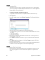
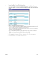
,QWURGXFWLRQ ,QVWDOOLQJ$SSUHQWLFH5HPRWHIRU)733UHSDUDWLRQ (VWDEOLVKLQJXVHUULJKWV &UHDWLQJFXVWRPL]HGILOHV &XVWRPL]LQJWKH:RUN2UGHU'HIDXOWV ,QVWDOOLQJ5HPRWHIRU$S)73DWWKHVLWH 0HQX6HOHFWLRQV )LOH &RPPXQLFDWLRQV +HOS &RPPDQG/LQH2SWLRQV $S)WSILOHQDPH! $S)WSVILOHQDPH! $S)WSF $S)WSXXVHUQDPH!SSDVVZRUG!KKRVWQDPH! $SSHQGL[%
$S0RGHP
,QWURGXFWLRQ ,QVWDOOLQJ$SSUHQWLFH5HPRWHIRU$S0RGHP3UHSDUDWLRQ &UHDWLQJFXVWRPL]HGILOHV ,QVWDOOLQJ5HPRWHIRU$S0RGHP &RQILJXULQJ$SSUHQWLFH5HPRWHIRUXVHZLWK$S0RGHP 2YHUYLHZ 0HQX6HOHFWLRQV )LOH &RPPXQLFDWLRQV :LQGRZV[&RQILJXUDWLRQ :LQGRZV17&RQILJXUDWLRQ 6FULSW +HOS 6FULSW)LOH 6FULSWFRPPDQGV -2%&200,1,)LOH.H\V &RPPDQG/LQH2SWLRQV $S0RGHPILOHQDPH! $S0RGHPVILOHQDPH! $S0RGHPF $S0RGHP[VFULSWILOH! 7URXEOHVKRRWLQJ)$4 7LSV *HQHUDOLQIRUPDWLRQ 0\0RGHP:LOO1RW&RQQHFW ,&DQ
W/RJ,Q ,*HW(UURUV:KHQ7UDQVIHUULQJ $SSHQGL[&
$S+RVW6HUYHU
,QWURGXFWLRQ 6HUYHU6HWXS 0LJUDWLRQIURP+\SHUDFFHVV 6WDUWLQJDQG6WRSSLQJ$S+RVW 3UHSDUDWLRQ 3UHIHUHQFHV 3KRQHOLQHV &UHDWLQJTXHXHV 8VHUV 8VLQJ$S+RVW 'H$FWLYDWLQJSKRQHOLQHV *HWWLQJLQIRUPDWLRQDERXWRQHSKRQHOLQH *HWWLQJLQIRUPDWLRQDERXWDOOSKRQHOLQHV +DQJLQJXSSKRQHOLQHV %URDGFDVWLQJPHVVDJHVWR5HPRWHXVHUV 5HDGLQJPHVVDJHVIURP5HPRWHXVHUV $SSHQGL['
$SSUHQWLFH8VHU0DQXDO
,QGH[
$SSUHQWLFH8VHU0DQXDO
$SSUHQWLFH
8VHU0DQXDO
Chapter 1
Introduction
This chapter describes the process of printing with Apprentice. It explains what Apprentice is,
who should use it and how it should be used.
What Is Apprentice?
Apprentice is a software program that is used for high-speed digital printing. The
complete Apprentice system consists of two major parts: Apprentice Server and
Apprentice Remote Client.
Apprentice Server
You can receive jobs via modem, ftp, network, diskette, ISDN or e-mail and modify
them through the same interface on which Remote Client users created them.
You also can buy optional scan-to-file functionality.
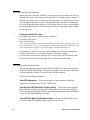
Apprentice Remote Client
These versions of the Apprentice Client have separate installations:
• Apprentice Remote Client allows communication via modem, FTP or LAN.
• Apprentice Remote LAN does not include modem or FTP functionality.
• Apprentice FM Remote is a subset of Remote LAN; users cannot create or open
queues, as they can with Remote LAN.
All three versions allow users to create a print job, and to process, preview and submit
drawings for printing. The Remote software provides feedback and pre-emptive
warnings before a print job is sent to Apprentice Server. All three versions allow users
to check prints on a Windows printer.
When Remote users are satisfied with the appearance of the drawing, they can send
the file to Apprentice Server, where it can be printed on a supported printer or saved
to diskette. Users, rather than the print-room operators, take responsibility for the
accuracy of output.
$SSUHQWLFH8VHU0DQXDO
The Concept
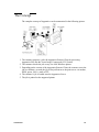
The complete concept of Apprentice can be summarized in the following picture:
1. The customer prepares a job with Apprentice Remote Client by processing
Apprentice files into the Vector Image Compressed (VIC) format.
2. The customer checks the job on any size local Windows printer.
3. Depending on the version of the Apprentice Remote Client, the customer saves the
job on a diskette, or sends the job to ProjectPoint or to the print server via modem,
ISDN, queue, LAN, e-mail or FTP.
4. The customer’s job is loaded onto the Apprentice Server.
5. The job is printed on the supported printer.
,QWURGXFWLRQ
Getting Help
In addition to the User Manual that is included on the installation CD, Apprentice
software version 4.31 provides HTML-based on-line help.
On-line help
If you need help while using the Apprentice software, the on-line help provides a
quick explanation of options and procedures.
•
Accessing on-line help
1. From the Help menu, choose Index. The Help dialog box opens.
2. Use the Contents, Index or Search tab as needed.
Tool tips
When your mouse pointer is over a button, Tool Tips provide a small box with a short
explanation of the button’s functionality.
Web site
You can find technical support information at www.buzzsaw.com. Visit the site for
updates, patches, suggestions and work-arounds.
$SSUHQWLFH8VHU0DQXDO
$SSUHQWLFH
8VHU0DQXDO
Chapter 2
Installation
This section focuses on the installation and configuration of Apprentice products.
Installing Apprentice
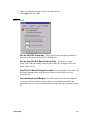
Before you install Apprentice, be sure to have the Install Key for the product(s)
available.
Note for customers who have been using Apprentice 4.25 or 4.25i: After you install
Apprentice, you must recustomize the work order for your Remote Client users.
Customers using JAWS may install Apprentice over previous versions that were
released in 2000 or 2001. The JAWS PS/PDF interpreter files will be unaffected.
However, if you wish to completely uninstall a previous version of Apprentice before
you install the new version, then you must back up two files (jawsnt.dll and
jawspm.exe) and three folders with all their contents (Font, Lib and Resource) and
copy them into the newest version’s installation directory.
During installation, Apprentice’s default pen set, logs and job settings are saved in a
default directory. If you are installing an upgrade, Apprentice will try to find previous
settings.
Please see www.buzzsaw.com for complete installation instructions.
$SSUHQWLFH8VHU0DQXDO
$SSUHQWLFH
8VHU0DQXDO
Chapter 3
The Software Interface
This chapter describes the different parts of the user interface. It also explains the different ways
in which options can be accessed.
Starting Apprentice
You can start Apprentice in several ways, just like any other Windows program.
Follow the procedure below. Quitting Apprentice is explained later in this chapter.
•
Starting Apprentice
Double-click the Apprentice icon on your desktop.
OR
From the Windows Start menu, click Programs>Buzzsaw>Apprentice.
$SSUHQWLFH8VHU0DQXDO
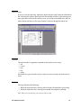
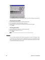
The User Interface
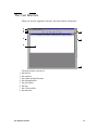
When you start the Apprentice software, the main window is displayed.
1.
2.
3.
4.
5.
6.
7.
8.
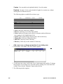
The main window consists of:
the title bar
the menu bar
the toolbar and quick menus
the information bar
the job window
the logo
the viewer toolbar
the status bar
7KH6RIWZDUH,QWHUIDFH
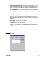
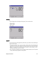
Menu bar
The menus available on the menu bar depend upon the mode in which you are
working. Below is an example from job mode.
When you click a menu name, its contents appear.
Toolbar and quick menus
The toolbar consists of two parts:
• Buttons with an icon. When you click a button, the corresponding option is
activated. The buttons contain the most frequently used option from the menu.
• Quick menus. When you click an arrow, a menu of options appears.
Note: Available buttons relate to the mode you are using. Some buttons are not available in
certain modes such as log or viewer.
Information bar
The information bar is on the left side of the main window.
• When you move your mouse over the information bar, its text is highlighted.
• When you click the information bar, it opens.
• If a drawing is selected, the bar provides information on the drawing settings. If
no drawing is selected, it displays a logo.
$SSUHQWLFH8VHU0DQXDO
Pen overview
If you are viewing a drawing, Apprentice shows the pens used, below the information
bar. Selecting one of these pens opens the Pen Settings window. If the drawing uses
more pens than will fit on the current screen, you can press and hold down the left
mouse button and move to the top or bottom, to browse through the whole list.
Window
The main window’s appearance depends on the mode you are using:
• job
• viewer
• pen
• log
• queue
More than one type of window may be open at a time, but only one mode may be
active.
Logo
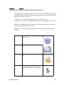
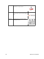
The logo indicates the following:
• When the logo turns into a moving sheet of paper, the program is processing.
• When the logo turns into a moving press/stamp, the program is printing.
Note: When you click the logo, the open job will be saved.
7KH6RIWZDUH,QWHUIDFH
Viewer toolbar
The Viewer toolbar is visible in every mode. But you can only use the buttons when
you are using the View mode.
The Viewer toolbar contains tools that make changes in the viewing mode. Some tools
do not affect the drawing and others do. The functions of the different tools are
explained in Chapter 8, Viewing Drawings, beginning on page 79.
Title bar
The Title bar is at the top of the window.
Status bar
There is a status bar at the bottom of the window, showing extra information about
selected windows or functions:
$SSUHQWLFH8VHU0DQXDO
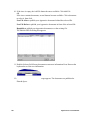
Accessing menus and options
Generally, there are several ways to open or use an option in Apprentice:
0HQXEDUWhen you click a menu, the contents of that menu appear. You can select
an option from the menu.
7RROEDUDQGTXLFNPHQXVWhen you click a button, the selected option appears.
When you click a quick menu arrow, a menu appears. You can select an option from
the menu.
5LJKWFOLFNWhen you click the right mouse button, a menu of the most
frequently-used options and settings appears. This method does not give you access
to all the available options.
'RXEOHFOLFNWhen you double-click the left mouse button with the pointer on a
setting, a list appears. You can choose an option from the list.
Note: Procedures that instruct you to “click” mean you should left-click once.
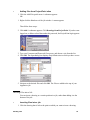
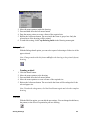
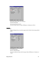
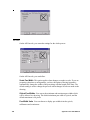
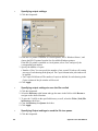
Setting preferences
In job mode, you can set preferences in the Options menu. The options can be set by
selecting them from the Options menu. A check mark next to an option indicates that
it is “On”, while an icon or no check mark indicates that it is “Off”.
,JQRUH3URPSWLQJ0RGHIf you check this option, the prompt windows will not
be displayed when problems occur.
Note: This option is recommended only for unattended printing.
3UHSURFHVVLQJ0RGHVIC files are stored in the VIC directory, which is created
during installation for quick processing and unprocessing. The drawback is that this
takes up space on your hard disk.
,JQRUH5&)+HDGHUVSelect this option to ignore the print information created by
an Ocp driver.
:LQGRZV3ULQWHU8VHV&RORUVCheck this option if you want to print to a
Windows color printer.
:LQGRZV3ULQWHU6FDOHThis option works only if you have purchased a
Remote Plus print code. Check this option if you want to print to a wide-format
Windows printer. Otherwise, if you are printing 100% of a large drawing to an 8.5x11
7KH6RIWZDUH,QWHUIDFH
page, a portion of the drawing will print at 100%. The rest of the drawing will print
on subsequent pieces of paper.
,QYHUW3DSHU,PDJHThe image is inverted so that black pixels are turned to white,
and white pixels to black. This option uses a lot of printer toner.
$XWRGHWHFWSDSHUVL]HIf this option is checked, the best fitting paper size will
be selected when the file is processed.
$XWR3DSHU5RWDWHIf this option is checked, the drawing will be rotated, if
necessary, in order to fit onto the selected paper size.
6DYH-RE'HIDXOW6HWWLQJV1RZSelecting this options will change the default
job settings to the most recently changed settings in the job window.
&OHDQ9,&GLUHFWRU\Deletes existing files from the VIC directory.
$SSUHQWLFH8VHU0DQXDO
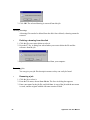
Quitting Apprentice
If you have finished working with Apprentice, quit the application. Do not quit
Apprentice while jobs are still being printed. It is a good practice to make sure that
jobs sent to the printer have been completed before quitting Apprentice.
•
Quitting Apprentice
1. Wait until the active job has been completely sent to the printer.
2. From the File menu, choose Exit. The Apprentice software is closed.
7KH6RIWZDUH,QWHUIDFH
$SSUHQWLFH8VHU0DQXDO
$SSUHQWLFH
8VHU0DQXDO
Chapter 4
Configuration
This section focuses on the installation and configuration of Apprentice products.
Configuring Major Products
During installation, Apprentice’s default pen set, logs and job settings are saved in
default directories. If you are installing an upgrade, Apprentice will try to find
previous settings. It is recommended that you leave the directories as if you have just
upgraded. If you wish to check or change settings, follow these steps:
•
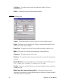
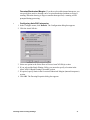
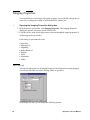
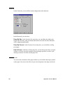
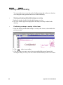
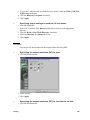
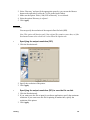
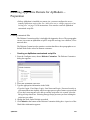
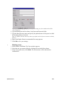
Configuring major products
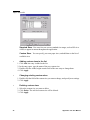
1. Open Apprentice.
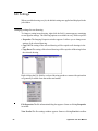
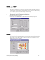
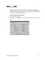
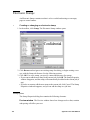
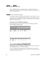
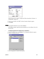
2. From the Configure menu, choose Defaults. The Configuration dialog box appears:
3. Make changes as needed on each tab. You need to start a new job for some selections
to take effect. See Handling Jobs, beginning on page 47 .
4. Click Apply to save the changes without closing the Configuration dialog box, or
click OK to save the changes and close the dialog box.
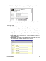
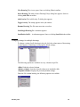
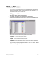
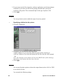
General tab
9LHZHUKDVEODFNEDFNJURXQGSelect this check box if you want to always have
a black background when you open the viewer.
8VH/DUJH)RQWIRU:LQGRZV5HSRUW3ULQWLQJSelect this check box to
specify that large fonts should be used to make reading easier when you print an
electronic job ticket.
$SSUHQWLFH8VHU0DQXDO
$OORZ)ROGLQJ&ROXPQLQ-RESelect this check box to allow selection of a
folding method from the job window. The folding column will appear in the job
window, even if there is not a folding unit attached to any configured printer.
-RE7LFNHW5HTXLUHGIf you select this check box, the work order appears and
must be filled out before the job can be sent or printed in any major Apprentice
product. In FM Remote, the work order must be filled out in all instances, even if this
check box is not selected.
%DQGHG0HPRU\6L]HThe amount of banded memory that will be used when
printing a file on a Windows printer. Increasing the banded memory size may
improve Apprentice performance, but will reduce the memory available to other
applications.
*OREDO8QLWVThe default unit of measurement.
$FFRXQWLQJSelect one of the following:
• Standard Accounting: Information will be written in and read from binary files
• ODBC Set: Uses Set Accounting table
• ODBC Sheet: Uses Accounting Information table
For more information about the types of accounting, see ‘Preparing Apprentice for
Accounting’ on page 155.
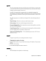
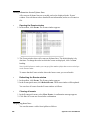
Communications tab
$GGTo add a communications method. For more information, see ‘Adding a
communications method’ on page 124.
&RQILJXUDWLRQ
&RQILJXUHTo configure the selected communications method. For more
information, see
'HOHWHTo delete the selected communications method.
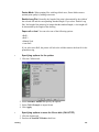
Job Default Settings tab
&RSLHVThe default number of copies to print for each file added to the job.
=RRPThe zoom ratio for printing a job. Choose a zoom ratio between 25% and
400%. You can also select Fit Page.
3DSHU6L]HThe paper size that will be used when a drawing is added to a job.
0HGLDThe media used. Choose bond, transparent or film (polyester).
$OLJQPHQWThe alignment that will be used.
5RWDWLRQThe required rotation in degrees and whether you wish the drawing to be
mirrored.
%RUGHU5HPRYDOThe required border removal. Choose from the following: none,
0.05” (1.3mm), 0.10” (2.5mm), 0.25” (6.3mm), 0.50” (12.7mm).
3HQ6HWThe name and path of the pen set that must be applied each time a drawing
is added to a job.
0DNH3DSHU6L]HVDPHDV'UDZLQJ6L]HSelect this check box to have
Apprentice set the paper size equal to the drawing size for those file formats in which
it can detect the size: Tif and Cals.
$SSUHQWLFH8VHU0DQXDO
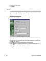
Directories tab
'HIDXOW3DWKIRU-RE)LOHVThe default path and directory where job files will be
stored.
'HIDXOW3DWKIRU9,&)LOHVThe default path and directory where VIC files will
be stored.
'HIDXOW3DWKIRU3HQ)LOHVThe default path and directory where pen files will
be stored.
'HIDXOW3DWKIRU/DEHO)LOHVThe default path and directory where label files
will be stored.
'HIDXOW3DWKIRU'UDZLQJVThe default path and directory that will be searched
for files to be added to a job.
'HIDXOW3DWKIRU6FDQVThe default path and directory for scan-to-file jobs.
5HPHPEHUODVWSDWKIRUGUDZLQJVSelect this check box to make the
application retain the last directory used in Add Files.
PostScript tab
These settings must be defined if you install an optional third-party product to
convert PostScript files to TIFF. Further information can be found in the third-party
product documentation.
&RQILJXUDWLRQ
Ghostscript is PostScript processing software that you can install to use with
Apprentice. The first time you process a PostScript file in Apprentice, you will be
asked whether you wish to install Ghostscript. You will be redirected to the
Ghostscript Web site, and an installation wizard will guide you through the process.
You can choose Jaws or GhostScript as your converter. If you use one, you should also
check for additional options in Apprentice’s Configuration Manager, the graphical
user interface for the XML-based job settings file. See File Processing on page 43.
.
3RVW6FULSW2XWSXW'LUHFWRU\The location where the processed files will be
stored. The default is C:\VIC or D:\VIC.
-DZVIf Jaws is installed on your system, this button will be available. You can
choose the resolution from the list or enter a number between 200 and 1200.
*KRVWVFULSWIf Ghostscript is installed on your system, this option will be available.
Enter the location of the executable file in the text box or use the Browse button to
navigate to the desired location. Choose a resolution between 200 and 1200 from the
list.
2WKHU6RIWZDUHReserved for other PostScript processing software. If you would
like to test another application, enter the executable file name here.
•
Establishing PostScript settings
1. If available, choose Jaws or Ghostscript.
2. Type the location of the executable or click Browse and navigate to the desired
location.
$SSUHQWLFH8VHU0DQXDO
3. Choose a resolution between 200 and 1200 from the list.
4. Click Apply, then click OK.
AutoCAD tab
8VHWKH$XWR&$',QWHUSUHWHUSelect this to use the interpreter included in
Apprentice. It supports AutoCAD R2.5-R2000 files.
8VHWKH$XWR&$'5%DWFK3ORWWLQJ8WLOLW\Select this to use the
AutoCAD R14 Batch Plotting Utility for processing files. It supports files from
AutoCAD R2.5-R14.
$XWR&$'5%DWFK3ORWWLQJ([HFXWDEOHIf you selected Use the AutoCAD
R14 Batch Plotting utility in the previous section, use this field to select the
executable file.
2YHUVL]HG8QGHUVL]HG0DUJLQVIf you have selected the internal interpreter,
you can specify how much a drawing can be oversized/undersized before the
application warns you. See Checking and Processing Drawings, beginning on page
61 .
&RQILJXUDWLRQ
Paper Sizes tab
6WDQGDUG6L]HVYou can select one or more standard size ranges, such as ISO-A or
ANSI, to appear in menus throughout the application.
&XVWRP6L]HVYou can specify your own paper sizes, and add them to the list of
available sizes.
•
1.
2.
3.
4.
Adding custom sizes to the list
Click Add. An entry is added to the list.
In the entry space, type the name of the new custom size.
Double click the width, height or units field of the new entry to change them.
Click Apply.
•
Changing existing custom sizes
1. Double click the field of the custom size you want to change, and specify new settings.
2. Click Apply.
•
Deleting custom sizes
1. Select the custom size you want to delete.
2. Click Delete. The selected custom size will be deleted.
3. Click Apply.
$SSUHQWLFH8VHU0DQXDO
Introduction to Configuration Manager
The JOB.XML file stores all of the configuration settings for Apprentice. The
Configuration Manager allows you to view and modify the settings stored in job.xml.
It is strongly recommended that all modifications be made through the Configuration
Manager rather than the job.xml file
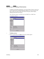
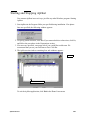
Using the Configuration Manager
The Configuration Manager is easily opened from the Configure menu of the
Apprentice application window.
•
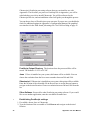
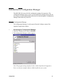
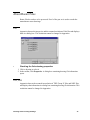
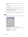
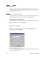
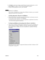
Accessing the Configuration Manager
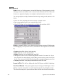
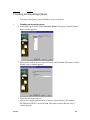
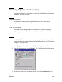
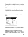
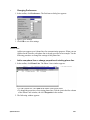
1. From the Configure menu, choose Advanced.
2. The Configuration Manager window appears:
Note: The program settings displayed in this window depend on the Apprentice
Server version (for example, Inkjet or 9400) installed on your system.
&RQILJXUDWLRQ
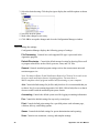
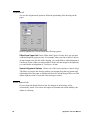
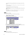
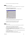
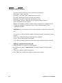
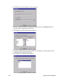
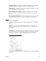
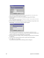
3. Select the desired setting. Click the plus sign to display the available options as shown
below.
4. Select the desired option.
5. Make other changes as necessary.
6. Click OK to accept the changes and close the Configuration Manager window.
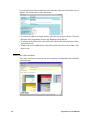
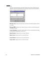
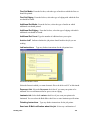
Understanding the settings
Configuration Manager displays the following groups of settings:
)LOH3URFHVVLQJControls how each supported file type is processed in the
Apprentice program.
'HIDXOW'LUHFWRULHVControls the default storage location for drawing files as well
as program related files such as labels, pen sets, scans, and VIC files.
*HQHUDOControls standard program settings such as the measurement units and
maximum paper size.
Note: You must set Honor E-mail Notification Request by Clients to Yes in order to use
the new e-mail notification feature in printing queues. You must have a
MAPI-compliant e-mail program installed and functioning on your computer.
-REControls default settings for job files and job tickets. It is recommended that you
set this to No if you are running Apprentice Océ 9800, 9400 or Inkjet Server so that it
does not conflict with the automatic print queue feature.
$FFRXQWLQJControls the default system used for logging accounting information.
3HQControls the default settings for any newly created pens.
3ULQWControls default print settings for a specified printer such as banner page,
collation, delivery, and folding options.
4XHXHControls the default settings for queue administration and reporting.
6FDQControls scan resolution, viewing, and template settings.
$SSUHQWLFH8VHU0DQXDO
6HFXULW\Displays the CD keys and print secure codes used for installing the
Apprentice program and printing to one of the supported printers.
,PDJH9LHZHUControls the properties of the Viewer window such as background
color.
&RPPXQLFDWLRQVControls the communication methods used for transferring
jobs between the Apprentice Server and Remote applications.
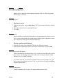
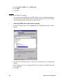
Locating specific settings
Since there are so many settings that can be modified, a find feature is incorporated
into the Configuration Manager.
•
Locating specific settings
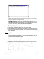
1. Enter a text string resembling the desired setting as closely as possible.
2. Click Find Next. The first setting containing the text string appears.
3. Click Find Next again to locate the next setting.
Note: To access previous search strings, click the arrow at the right side of the text
box. A menu of previous search strings appears.
&RQILJXUDWLRQ
$SSUHQWLFH8VHU0DQXDO
$SSUHQWLFH
8VHU0DQXDO
Chapter 5
Work Order Customizer
This chapter describes the Apprentice Work Order Customizer, which allows you to tailor a print
order form with printer and sender information. The information is then used for accounting
purposes.
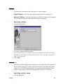
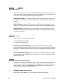
Accessing the Work Order Customizer
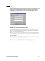
From the Configure menu, choose Work Order Customizer. The form appears,
separated into three Work Order Customizer sections:
Order Receipt Header
The Order Receipt Header lets you control company logo, address and other
information.
You can make changes in the fields and view the output in the header. To make
changes to text, type new information in the text boxes.
•
Changing the logo
1. Click Browse. The Choose File dialog box appears.
2. Navigate to the image you wish to use.
$SSUHQWLFH8VHU0DQXDO
3. Click Open. The path to the image appears in the Logo Bitmap text field
.
4 Use the minus (-) or plus (+) signs to decrease or increase the height and width.
Work Order fields
Work Order Fields let you control how fields appear to clients.
• Required: Required fields must be visible to the client so that Apprentice’s
accounting functions can process them. Clients must fill in the required fields before
they send jobs.
• Visible: You can make non-required fields visible to the client. Visible fields appear
on a job ticket but are not mandatory.
• Always Blank: When a field is not visible, the Always Blank check box will be
selected automatically.
• Default Value: Visible fields can have default values so that clients don’t need to
enter information that will be the same for each job submitted.
:RUN2UGHU&XVWRPL]HU
Several work order fields contain lists from which the client can choose from a set of
options. These lists can be easily customized.
• To remove text that is no longer needed, select the text and press Delete. Click the
Reformat Lines hyperlink to remove any blank lines from the list.
• To add text at the end of a list, click at the end of the last line of text and press Enter.
Type the new text.
• To add a line of text within the list, click at the end of a line of text. Press Enter. Type
the new text.
Work Order colors and fonts
The Colors and Fonts section lets you select typefaces, background colors and other
visual elements.
$SSUHQWLFH8VHU0DQXDO
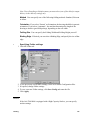
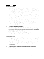
Previewing the Work Order Changes
To view how the form will look with the options you selected, click the Submit button.
The preview form appears:
• Click Back to make other changes in Work Order Customizer.
• Click Save Changes to save the Work Order Customizer options you selected.
• Click Close to close the form without saving changes.
:RUN2UGHU&XVWRPL]HU
Distributing the Customized Work Order
For LAN environments, the Configuration Manager allows all network stations to use
the same customized work order without having it installed on each station. For more
information on Configuration Manager, See ‘Introduction to Configuration Manager’
on page 37.
•
1.
2.
3.
4.
5.
6.
Using the Work Order Customizer directory
On the client machine, open the Configure menu.
Click Advanced. The Configuration Manager appears.
Click the plus sign (+) next to Default Directories to expand it.
Click the Customized Work Order Files item to select it. A field appears in the lower
part of the Configuration Manager form.
To change the default directory, click in the field and type the full path for the new
directory or click Browse and navigate to the desired location.
Click OK.
Note: Logobitmap2.gif is the default graphic that is installed with Apprentice. If a
customer chooses a different graphic, Apprentice copies it into the installation
directory and renames it logobitmap.gif. If a customer adds a .jpeg, Apprentice will
rename it with a .gif filename extension and will display it correctly.
If the remotes are not on the same network, the customized work order must be
distributed by manually copying files to the remote stations.
•
Transferring the customized work order to a remote system.
1. Find the following newly created files in your installation directory (usually
c:\buzzsaw)
• woinfo.xml
• logobitmap.gif.
2. Copy them to a floppy disk.
3. On the target machine, copy the two files into the Apprentice installation directory.
$SSUHQWLFH8VHU0DQXDO
$SSUHQWLFH
8VHU0DQXDO
Chapter 6
Handling Jobs
This chapter describes what a job is, how to manage jobs and how to change drawing settings
within a job.
Introduction
A job holds references to a set of drawings and controls that allow you to customize
each file in the set. You can change the order of the drawings within a job, set the
number of copies, resize each drawing, select a scale, choose a paper size and media
type, apply a pen set, align the images on the media, rotate the images, and remove
borders so you don’t waste paper. A job contains an electronic work order, also known
as a job ticket.
Jobs get the file name extension.JOB. If information is missing, Apprentice applies a
default pen set and a blank work order. Apprentice allows you to have multiple jobs
open simultaneously.
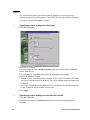
Creating new jobs
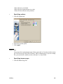
When Apprentice is started a job window, called Job 1, will appear. To create another
new job, follow this procedure.
•
Creating new jobs
1. From the File menu, choose New. A dialog box appears.
2. Select Job, and click OK.
3. A job window opens. You have created a new job.
Adding files to jobs
A new job does not contain any files. Drawings to be printed must be placed in a job.
•
Adding files to jobs
1. In the toolbar, click Add Files. The Add or Insert Drawings dialog box appears.
2. Navigate to the location of each drawing to be added and click it. Shift-click to select
a range of files or Control-click to select multiple, separated files.
3. Click OK. The drawing files are added to the job.
Adding drawings from ProjectPoint™ sites
You can transfer jobs and files between Apprentice and ProjectFolders sites. The
Apprentice job window must be active, and you must have a ProjectPoint account set
up to use this function in Apprentice. For more information, see chapter 12, ‘Sending
Jobs’ beginning on page 121.
$SSUHQWLFH8VHU0DQXDO
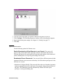
•
Adding files from ProjectPoint sites
1. Click the Add Files quick menu. A submenu appears.
OR
1. Right-click the blank area of the job window. A menu appears.
Then follow these steps:
2. Click Add. A submenu appears. Click Drawings from ProjectPoint. If you have not
logged on, or did not select Remember this password, the ProjectPoint login appears:
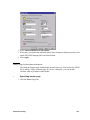
3. Type your Username and Password if necessary, and choose a site from the list.
4. Click OK. The Open dialog box displays ProjectPoint sites to which you have access:
5. Navigate to the desired files and click OK. The files are added to the top of your
Apprentice job.
Inserting Files into a Job
You can insert a drawing at a certain position in a job, rather than adding it to the
bottom of the job:
•
Inserting files into a job
1. Click the drawing that is below the point at which you want to insert a drawing.
+DQGOLQJ-REV
2. From the Add Files quick menu, choose Insert Drawing. The Add or Insert
Drawing(s) dialog box appears.
3. Navigate to the location of the drawings to be added.
4. Click the drawing(s) you want to add. Shift-click to select a range of files or Ctrl-click
to multiple, separated files.
5. Click Open. The drawing files are inserted above the highlighted drawing.
Adding files from a text file
You can use a special text file to add several drawings at once. It should be formatted
with each line specifying the path of a drawing to be added.
•
1.
2.
3.
4.
5.
Adding new files from file list
In a text editor, type the path and filename of every drawing, each on a separate line.
Add a blank line to the end of the file list.
Save and close the text file.
Open Apprentice.
In the Add Files quick menu, select Add Drawings.
Select the file that you saved with the text editor. Every file in the list is added to the
current job.
Saving jobs
When you have defined all the settings for each drawing in a job, save the job to retain
these settings.
•
Saving a job
1. From the File menu, choose Save Job. The Save As dialog box appears.
Note: If you have opened a job and want to save it under a different name, then use the
command: Save Job As, rather than using Save.
2. Select the drive and directory where you want to save the job.
3. Type a filename for this job.
4. Click Save. The job is saved.
Closing jobs
You can also close a job without saving it. Use this option if you have made a mistake
in handling a job.
$SSUHQWLFH8VHU0DQXDO
•
Closing jobs
1. Make sure the job you wish to close is active.
2. From the File menu, choose Close. If you have made any changes, Apprentice will
ask you if you want to close the job without saving it. Otherwise, if you have made no
changes, the job simply closes.
Opening existing jobs
You can use job files that have been saved on the print server, on a network
workstation, or on diskette. You can use a previously saved job by opening it.
•
Opening jobs
1. From the File menu, click Open. The Open dialog box appears.
2. Navigate to the desired job, and click it to select it.
3. Click Open. The selected job opens.
Merging jobs
You can add the contents of one job to another. Drawings will be placed in the order
in which they are merged.
•
1.
2.
3.
4.
Merging jobs
Open the first job to be merged.
From the File menu, choose Merge Job File. The Merge Job File dialog box appears.
Navigate to the job file you would like to add.
Click Open. The second job’s contents are added to the first job’s.
Removing drawings from jobs
A drawing can be removed from a job. A copy remains in the system but its reference
is not visible in the job window.
•
Removing a drawing from a job
1. Click the file you want to remove to select it.
2. From the Add Files quick menu, choose Delete Drawing. A message asks you to
confirm the deletion.
+DQGOLQJ-REV
3. Click OK. The selected drawing is removed from this job.
Deleting drawings
A drawing file can also be deleted from the disk. Once deleted, a drawing cannot be
restored.
•
Deleting a drawing from the disk
1. Click the file you want to delete to select it.
2. Press the F7 key. A dialog box asks whether you want to delete the file and the
reference from the job.
3. If you are sure, click OK. The file is erased from your computer.
Renaming jobs
You can give your job files descriptive names so they can easily be found.
•
Renaming a job
1. Click the job to select it.
2. From the File menu, choose Save Job As. The Save As dialog box appears.
3. Enter a new name for the job file, and click Save. A copy of the job with the new name
is saved, and the original with the old name remains on disk.
$SSUHQWLFH8VHU0DQXDO
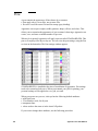
Organizing Drawings Within a Job
Drawings can be skipped, moved and copied to organize them within a job.
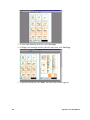
Skipping drawings within a job
You can skip drawings that you don’t want to print but do want to keep in the job. If
you use Apprentice to send the job over a network or modem, skipped files will not
be transferred.
•
Skipping a drawing in a job
To skip a drawing, deselect its button in the far left column. A red line appears through
the job information.
Moving drawings within a job
You can reposition drawings within a job to change the printing order.
•
Moving a drawing within a job
1. Click the drawing you want to move to select it.
2. Press and hold down the left mouse button while dragging the drawing to the desired
position.
3. Release the mouse button. The drawing is moved.
Copying drawings within a job
You can make copies of a drawing inside a job.
•
1.
2.
3.
4.
Copying a drawing
Select the drawing you wish to copy.
Press and hold down the right-hand mouse button.
Move the drawing to the desired position.
Release the right-hand mouse button. The drawing is copied.
+DQGOLQJ-REV
Job Settings
When you add a drawing to a job, the default settings are applied and displayed in the
job window.
Changing settings for one drawing
To change a setting in one drawing, right-click the field. A menu appears, containing
several popular settings. The following options are available in every field except File:
• Properties The Imaging Properties window appears. It allows you to change most
settings of the selected drawing.
• Copy All The setting of the selected drawing will be copied to all drawings in the
job.
• Copy Down The setting of the selected drawing will be copied to all drawings below
the selected drawing.
Right clicking the File field for a selected drawing produces a menu with options that
are generally available from the toolbar and menus:
File Properties The file information dialog box appears. Same as clicking Properties
in toolbar.
View Pen Set The Pen settings window appears. Same as clicking Pen Set in toolbar.
$SSUHQWLFH8VHU0DQXDO
View Drawing The viewer opens. Same as clicking View in toolbar.
Insert Drawing The Add or Insert Drawing File(s) dialog box appears. Same as
clicking Add Files in toolbar.
Add Overlay The Add Overlay To dialog box appears.
Toggle Overlay The stamp appears in the job window.
Rename Drawing The file name turns into a text box.
Send Single Drawing To A submenu appears.
Send Entire Job To... A submenu appears. Same as clicking Send Job in the toolbar.
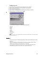
Changing settings for multiple drawings
To change a setting for all drawings in the job, click the column name of that setting.
A menu appears, containing several popular default settings.
The following options are available in every column except File:
• Hide: Hides the selected column.
• Reduce columns: Sets the selected column to its standard width.
• Expand columns: Displays all previously hidden settings.
From the File column heading, the following options are available:
+DQGOLQJ-REV
File
The File column displays the name of the file in the job. The filename extension tells
you the file format. The icon to the left of the filename shows the status of the file (for
example, Processed, Printed, Viewed, etc.).
Some HP-GL formatted files incorporate their own embedded commands for
specifying pen colors and pen widths. If Apprentice processes such a file, the icon in
front of the drawing’s filename becomes a green check mark instead of a black check
mark.
The following options are available by clicking the File column heading in the job
window:
6KRZ2YHUOD\VShows the overlay (text and electronic stamp).
+LGHRYHUOD\VHides the overlaid drawings from the job list.
3URFHVV'UDZLQJ)LOHVThis command converts native drawing files (vector files)
into VIC files for fast printing.
&KHFN'UDZLQJ)LOHVIf you click this option, the drawing files will be checked for
potential clipping and pen set problems, and processed.
8QSURFHVV$OO'UDZLQJ)LOHVThis command unprocesses the VIC files into
their native format.
Copies
Using the Copies field, you can change the number of copies.
•
Changing the number of copies
1. Right-click the Number of Copies field of the drawing. The Number of Copies menu
appears.
2. Click the desired setting.
3. Click outside the drop-down menu to remove it.
Drawing Size
This field displays the original size of the drawing.
$SSUHQWLFH8VHU0DQXDO
Zoom
You can specify the zoom factor as follows:
•
Making an enlargement or reduction
1. Right-click the Zoom field of the drawing you want to change. The Zoom menu
appears.
2. Select the desired zoom setting:
• One of the predefined zoom factors.
• Fit Page: Zoom factor will be changed automatically to fit the specified Paper Size.
• 50% Reduction or 200% Enlargement: The paper size will automatically change to
fit the drawing.
Note: If you select either 50% reduction or 200% enlargement, the media size will
automatically change with the size of the drawing. For other zoom settings, you must also
change the paper size. If you wish to set a custom zoom percentage, choose Select from
the menu.
• Select: The Imaging Properties window appears, to specify a custom zoom factor.
3. Click outside the Zoom menu to remove it.
4. In the Imaging Properties window, click OK.
Paper Size
You can select from a variety of standard paper sizes to print on, or you can define
custom paper sizes.
•
1.
2.
3.
4.
Changing the paper size
Right-click the Paper Size field of the drawing you want to change. The Paper Size
menu appears.
Using the mouse pointer, select the desired paper size:
• One of the pre-defined paper sizes.
• User size: The Imaging Properties window appears, allowing you to specify a
custom paper size.
Click outside the Paper Size menu to remove it.
In the Imaging Properties dialog box, click OK.
Media Type
You can print digital drawings on different types of media: bond, vellum, or film.
•
Changing the media type
1. Open the job that contains the required drawings.
+DQGOLQJ-REV
2. Right-click the Media field of the drawing you want to change. The Media Type menu
appears.
3. Select the desired media type.
4. Click outside the drop-down menu to remove it.
Fold
You can select from a variety of standard folding methods, or define a custom folding
method. Folding is available only if the printer is equipped with a folding unit.
•
1.
2.
3.
4.
Selecting the folding method
Open the job that contains the required drawings.
Right-click the Fold field of the drawing you want to change. The Fold menu appears.
Select the desired folding method:
• One of the pre-defined folding methods.
• Select: The Imaging Properties window appears, enabling you to specify a custom
folding method.
Click outside the drop-down menu to remove it.
Pen Set
•
Changing the pen set
1. Right-click the Pen Set field of the drawing you want to change. The Pen Set menu
appears.
2. Click Select New Pen and then navigate to the desired *.pen file, or click View
Current Pen to change the current pen set.
3. Close the Pen Set window to remove it.
Alignment
You can specify how your drawing is positioned on the paper in relation to the edges
of the selected paper size.
•
Changing the alignment
1. Right-click the Alignment field of the drawing you want to change. The Alignment
menu appears.
2. Select the desired alignment setting:
• One of the pre-defined alignment settings.
$SSUHQWLFH8VHU0DQXDO
• User size: The Imaging Properties dialog box appears, allowing you to specify a
custom alignment.
3. Click outside the Alignment menu to remove it.
Rotation and Mirror
You can define whether and how to rotate the drawing on the paper.
•
Changing the rotation
1. Right-click the Rotation field of the drawing you want to change. The Rotation and
Mirror menu appears.
2. Choose a rotation or mirrored position.
3. Click outside the menu to close it.
Border Removal
You can electronically remove trim marks and borders from the drawing.
•
1.
2.
3.
4.
Removing the border
Right-click the Border Removal field of the drawing you want to change. The Border
Removal menu appears.
From the menu, select a pre-defined setting or click Properties to display the Imaging
Properties window.
If you selected Properties, make changes as needed and click OK.
Click outside the Border Removal menu to remove it.
Color
The color column indicates whether the file should be printed on a color printer via
PSOut or HPGLOut. The default is no. Apprentice does not autodetect whether a file
is color.
+DQGOLQJ-REV
$SSUHQWLFH8VHU0DQXDO
$SSUHQWLFH
8VHU0DQXDO
Chapter 7
Checking and Processing Drawings
This chapter describes how to check and change drawing file properties, and explains how to
process and unprocess a job.
About Processing and Checking Files
Apprentice processes vector files by converting them into a high-speed, proprietary
format known as Vector Image Compressed (VIC). The VIC format allows
WYSIWYG viewing and improves performance of supported printers.
Apprentice does not process or convert raster files, although sometimes it compresses
the raster data when the files are sent to a supported printer.
In a job, icons show the native-format of unprocessed files. A check mark indicates a
processed file.
Apprentice checks files while it process them to make sure all pens have been
assigned a weight and drawings will not be clipped.
$SSUHQWLFH8VHU0DQXDO
Vector vs. Raster
Drawing files can be divided into two main types:
• Vector files
• Raster files
Apprentice processes the following vector formats into VIC format and checks the
processed files:
• AutoCAD DWG.
The internal interpreter supports AutoCAD R2.5-R2000 files.
• Data Exchange Format (DXF)
• HP-GL, HP-GL/2, HP RTL
• CalComp 906/907 PCI
• PostScript Level 3, using an optional PostScript converter
Apprentice checks files in the following raster formats but does not process them:
• CALS (Group 4, type 1)
• NIFF (Group 4)
• TIFF single page monochrome
• Group 4 (6.0; tiled, striped; reverse bit order)
• Group III
• Packed bits
• Uncompressed
About AutoCAD formats
Apprentice treats AutoCAD format files, such as DWG and DXF, slightly differently
than other vector formats. In addition to pen weights, it checks fonts and
external-reference file.
Note: PostScript and True Type fonts are not supported. They should be replaced with SHX
fonts.
&KHFNLQJDQG3URFHVVLQJ'UDZLQJV
Drawing Properties
For each type of drawing, you can open a properties window. Depending on the type
of drawing, this window can be used for different purposes.
The General tab of the drawing properties window always contains information about
the file type, file size and file date.
When Apprentice checks drawing files, it checks to make sure that all pens have been
assigned a pen width and that the drawing will not be clipped.
For AutoCAD files, it also checks that the path for the font and other cross-references
is correct, and that the scale is correct. If there is an error, a warning message will
appear.
Further information depends on the type of drawing, and is described in the following
sections.
$SSUHQWLFH8VHU0DQXDO
AutoCAD Files
For each type of drawing, you can open a properties window. Depending on the type
of drawing, this window can be used for different purposes. For AutoCAD drawings
you can specify specific AutoCAD settings, such as scaling.
•
Opening the AutoCAD properties dialog box
1. Click the drawing file to select it.
2. In the toolbar, click Properties. The Drawing Properties dialog box appears.
General tab
The General tab of the drawing properties window always contains information about
the file type, file size, and file date. If a preview of the files is available, it will be
displayed in the preview window.
&KHFNLQJDQG3URFHVVLQJ'UDZLQJV
Plot by/Scale tab
6FDOHScale is of vital importance in AutoCAD drawings. When Apprentice checks
drawings, it makes sure that the scale is correct for the selected media size. If the scale
is incorrect, Apprentice displays a warning box and estimates the correct scale.
You can specify the scale by a fraction of an inch or by setting a scale, such as 1=20
inches.
• Select one of the standard scale factors from the available entries.
• Enter a non-standard scale factor, using the Other field.
• Select Fit To Paper, to force Apprentice to calculate the scale that will fit.
3ORWE\Apprentice allows you to choose how the drawing is printed. If the drawing
is not displaying correctly in the Viewer, check that the correct option was set in Plot
By.
• Extents prints all the objects in the drawing.
• Limits prints the current drawing limits.
• Display prints the view as displayed in AutoCAD
• View prints a named view of the drawing chosen from the View name list. If you
have selected View in the Plot By section, then you must select a named view from
the list. If no views are defined in the drawing, this command will appear grayed out.
• Layout prints based on layouts predetermined in AutoCAD 2000.
/D\RXWWR3ORWThis list box displays the AutoCAD layouts available for plotting.
8VH6DYHG([WHQWVThis option applies only to drawings in Model Space. Select
this box to use the extents that are saved in the drawing file for plotting by extents.
This allows drawings to be processed much faster because the extents do not need to
$SSUHQWLFH8VHU0DQXDO
be calculated. In cases where the extents are saved incorrectly in the drawing file, you
may need to turn the option off so that the accurate extents can be recalculated.
8VH0HWULF6FDOLQJSelect this check box if you want to use millimeters instead of
inches.
The Plot By/ Scale tab will appear differently if the AutoCAD R14 Batch Plot Utility
is used to process DWG files. The options that are different are described below.
7H[W)LOOVDisplays text using the TextFill property in AutoCAD which fills text to
be solid rather than just an outline.
+LGH/LQHVDisplays objects in drawings using the HideFill property in AutoCAD
which hides background lines that normally appear in a 3D object.
$GMXVW$UHD)LOODisplays objects in the Drawing using the AdjustAreaFill
property in AutoCAD which pulls in the boundaries of the filled area one-half the pen
width.
&KHFNLQJDQG3URFHVVLQJ'UDZLQJV
Advanced tab
Apprentice reads information on this tab from the selected AutoCAD drawing file.
Apprentice looks for the information for each of the categories and if information is
found, it is displayed in the appropriate field.
GZJDGYWLI
0LVVLQJ)RQWVDisplays the font names used in the selected drawing that could not
be located.
0LVVLQJ;5()VDisplays any external references used in a selected drawing that
could not be located.
/D\HULQIRUPDWLRQApprentice displays the list of layers contained in the drawing
file and indicates whether they are on or off.
0RGHO([WHQWVDisplays the size in AutoCAD units.
0RGHO/LPLWVDisplays the size in AutoCAD units.
3DSHU([WHQWVDisplays the size in AutoCAD units.
3DSHU/LPLWVDisplays the size in AutoCAD units.
$SSUHQWLFH8VHU0DQXDO
Directories tab
Apprentice cannot process and print your drawing correctly if it does not know where
to look for the font files and external references. If Apprentice cannot find this
information, it will display an error message. Check that all paths are correctly
specified on the Directories tab.
•
Setting font and external reference paths
1. Check that the path in the AutoCAD font location in the SHX Path is correct. If
necessary, click the Browse button and navigate to the location in your computer
where your AutoCAD fonts are stored.
2 Check that the path to the AutoCAD application location in the XREF path field is
correct. If necessary, click the browse button and navigate to the location of your
external references.
Note: You can have multiple SHX Paths and XREF Paths if you separate the name of each
with a semicolon. Apprentice will check all of them.
3. Check that the name of the Default font used in the drawing is correct.
Note: You can use wild cards, such as C:\auto*, to look in multiple directories.
&KHFNLQJDQG3URFHVVLQJ'UDZLQJV
Solving AutoCAD scale problems
When you receive an AutoCAD.DWG, you may need to set or change the scale of a
drawing. The correct scale must be set in order to have drawings correctly printed. If
the drawing is going to be too large for the selected paper size, Apprentice will warn
you and suggest an estimated scale. The estimated scale is based on comparing the
size of the digital drawing with the size of the paper. However, there is no substitute
for knowing the actual scale of a drawing and, ideally, the drawing’s author should
provide the scale.
•
Setting an AutoCAD scale
1. Set paper size to the size requested by the customers.
2. Set scale to Full (100%).
3. Process the drawing.
Note: Apprentice will process the drawing and warn you that the drawing is the wrong size
for the selected paper size. It will also suggest an estimated AutoCAD scale. However, it will
often estimate on the low side, so try the next higher standard AutoCAD scale.
4. If the drawing is still the wrong size, find out whether the customer is plotting by
extents, limits, display or view. Most customers will plot by extents.
5. As a last resort, set the AutoCAD scale to Fit to Page, and view the drawing’s title
block. Often, the scale of the drawing will be contained in the title block.
Configuring AutoCAD processing
The internal interpreter supports AutoCAD R2.5-R2000 files, and will normally be
used for all AutoCAD drawings. It is, however, possible to use the AutoCAD Release
14 batch plot utility instead, if you have AutoCAD R14 installed.
Select one of the following options:
$XWR&$',QWHUSUHWHUSelect this option to use the interpreter included in
Apprentice. It supports AutoCAD R2.5-R2000 files.
8VHWKH$XWR&$'5%DWFK3ORWWLQJ8WLOLW\This uses the AutoCAD R14
Batch Plotting Utility for processing files and supports files from AutoCAD R2.5 R14. You can specify the path and name of the batch plotting utility in the field named
‘AutoCAD R14 Batch Plotting executable’.
$XWR&$'5%DWFK3ORWWLQJ([HFXWDEOHSelect the executable file to use if
you selected the Batch Plotting Utility in the previous section.
$SSUHQWLFH8VHU0DQXDO
2YHUVL]HG8QGHUVL]HG0DUJLQVIf you have selected the internal interpreter, you
can specify how much a drawing can be oversized/undersized without receiving a
warning. When the drawing is larger or smaller than specified, a warning will be
prompted during processing.
•
Configuring AutoCAD interpreter
1. In the Configure menu, click Defaults. The Configuration dialog box appears.
2. Click the AutoCAD tab:.
3. Select one option in the Select How to Process AutoCAD file(s) section.
4. If you selected the Batch Plotting Utility, you must also specify a location in the
AutoCAD R14 Batch Plotting Executable section.
5. If required, specify limits in the Oversized/Undersized Margins (internal interpreter)
section.
6 Click OK. The Drawing Properties dialog box appears.
&KHFNLQJDQG3URFHVVLQJ'UDZLQJV
HP-GL, HP-GL/2 and HP RTL Files
Apprentice detects the drawing resolution and a number of other HP-GL-specific
options. It displays this information in a dialog box containing drawing file
information.
•
1.
2.
3.
4
Checking the HP-GL, HP-GL/2 and HP RTL drawing properties
Click the unprocessed HP-GL drawing file to select it.
In the toolbar, click Properties. A dialog box appears.
Check that the File Type and the Drawing Resolution are correct.
Click OK.
Note: If you use HP-GL/2 format drawing files, the pen control tab is also applicable.See
‘Pen Controls’ on page 111.
$SSUHQWLFH8VHU0DQXDO
CalComp 906/907 PCI Files
Apprentice detects the sync byte, end of message, checksum and the step size settings
in a CalComp file. This information is displayed in a dialog box containing drawing
file information (in decimal format). However, it is recommended that you check
these settings within the file before you print.
Checking the CalComp drawing properties
1. Click the unprocessed drawing file to select it.
2. In the toolbar, click Properties. A dialog box containing drawing file information
appears.
• To change Sync byte, select Single or Double sync and choose a value from the list
box.
• To change Step size, click the radio button to choose a preset value, or enter a value
in the Other files.
• Set the Use Checksum option to On or Off.
• To change the End of Message, use the arrows to enter a new value in the End of
Message field.
3. Click Apply, then click OK.
Note: Only change a CalComp setting if you really are sure that the ones checked and
suggested by Apprentice are incorrect.
&KHFNLQJDQG3URFHVVLQJ'UDZLQJV
Processing and Unprocessing Drawings
For fast printing, you can convert native DWG, DXF, HP-GL, and CalComp drawing
files into Apprentice VIC files. You can unprocess VIC files into their native format
if the original drawings are on the system. If you have received a native-format vector
file (as opposed to a VIC file), you can unprocess the drawing to make changes to
AutoCAD scale, or set stepping in CalComp plot files.
•
Processing one drawing file
Double-click the file name in the job list. The processed drawing displays in the
viewer.
•
Processing all drawing files in a job
From the Process quick menu, choose Process All Drawings. The job processes.
•
Unprocessing all vector drawing files in a job
From the Process quick menu, choose Unprocess All Drawing Files. The job
unprocesses.
•
Unprocessing a single drawing file
1. Click a drawing to select it.
2. From the Process quick menu, choose Unprocess Drawing. The selected drawing is
unprocessed.
Preprocessing mode
Preprocessing mode allows you to save the VIC files as well as the native format files
for the job. This can be useful for jobs that will be printed again soon, because they
will not have to be processed again. The drawback to this feature is that it uses extra
disk space.
•
Setting pre-processing mode
1. Open the job that contains the required drawings.
2. From the Options menu, choose Preprocessing Mode. Preprocessing mode is active.
Note: When you are updating drawings with the same file name, preprocessing mode will not
take this into account. Thus, the settings will be changed in the drawing, but will not be
changed in the VIC file.
$SSUHQWLFH8VHU0DQXDO
About Raster Files
Raster files do not have to be processed. Pen 0 of the pen set is used to render the
monochrome raster drawings.
Cals
Apprentice detects the image size and the scanned resolution of Cals files and displays
them in a dialog box. This resolution cannot be changed in Apprentice.
•
Checking the Cals drawing properties
1. Click a drawing to select it.
2. In the toolbar, click Properties. A dialog box containing drawing file information
opens.
TIFF, NIFF
Apprentice detects the scanned-in resolution of TIFF Group IV files and NIFF files,
and displays the information in a dialog box containing drawing file information. This
resolution cannot be changed in Apprentice.
&KHFNLQJDQG3URFHVVLQJ'UDZLQJV
•
Checking the TIFF drawing properties
1. Click the unprocessed drawing file to select it.
2. In the toolbar, click Properties. A dialog box containing drawing file information
opens.
$SSUHQWLFH8VHU0DQXDO
About LDF Files
LDF files do not need to be processed further. Files converted to LDF through
Apprentice or Plans & Specs are print ready. The LDF file properties dialog shows the
container structure associated with the file, along with the file name and description.
These cannot be changed in the dialog box.
•
Viewing an LDF file’s properties
1. Click the LDF file to select it.
2. In the toolbar, click Properties. A dialog box containing information about the file
appears.
&KHFNLQJDQG3URFHVVLQJ'UDZLQJV
$SSUHQWLFH8VHU0DQXDO
$SSUHQWLFH
8VHU0DQXDO
Chapter 8
Viewing Drawings
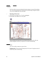
This chapter describes how to view a drawing and how to make changes using the Viewer tools.
Viewer
The Viewer allows you to see whether the drawing settings are correct before printing.
The Viewer has powerful tools for altering the way the drawing will appear on paper.
You can view multiple files at the same time.
•
Opening a file to view
1. Select the file you wish to view. The file is highlighted.
2. In the toolbar, click View. The viewer opens.
.
1RWH If you want to view multiple files, open them one by one.
The last settings you make before you save and close the View mode will be the
default settings the next time you open the View mode for that drawing.
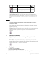
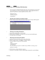
Viewer toolbar
The Viewer toolbar contains two types of tools:
9LHZLQJWRROVThese tools make changes only in View mode. Using these tools will
not have any effect on the drawing.
$SSUHQWLFH8VHU0DQXDO
(GLWLQJWRROVThese tools affect the drawing. You can see the changes in View
mode as well as in Print Preview mode.
Button
1DPH
$IIHFW
3ULQW
5HVXOW
Fit Page
Fit zoom so that the entire page is
visible
No
Zoom Select
Zoom in:
Left mouse
Zoom out:
Right mouse
Zoom in select: Left mouse & Drag
Shows the part of the drawing that is on top after
folding
No
Pan View*
Moves the view window over the
drawing
No
Move Drawing
Change the offset of the drawing on the page
Yes
Border Removal
Remove outside border of drawing
Yes
Crop Outside
Erase outside selected area
Yes
Enlarge detail
Enlarge selected area to fit paper.
Yes
Edit Pen
Identify or change current pen set
Yes
Center Drawing
Move the drawing to the center of the paper
Yes
Align
Title Block
Align the drawing at the right edge of the paper and
centers it vertically.
Yes
Mirror
Generates a mirrored image
Yes
Rotate Right
Rotates the drawing and paper
90 degrees clockwise
Yes
Rotate Left
Rotates the drawing and paper
90 degrees counter clockwise
Yes
Rotate 180
Rotate the drawing and paper
180 degrees
Yes
Negative paper
Reverse the background of the paper from white to
black
No
Toggle Rasterization
Switch from colored pens to black and white with
pen patterns and other pen characteristics
No
View Fold*
9LHZLQJ'UDZLQJV
'HVFULSWLRQ
No
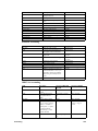
Button
1DPH
'HVFULSWLRQ
$IIHFW
3ULQW
5HVXOW
Toggle Color Patterns
Shows pen patterns of colored lines
No
Outline Polygons
Removes fills in polygons and polylines
No
3DQ9LHZ9LHZ)ROGThe
View Fold button appears only if the Apprentice
application is installed with Folding support. You must activate Folding in the file
settings of the selected drawing. The Pan View option is also available in the View
menu.
Zoom tools
The Fit Page and Zoom Select tools allow you to zoom in, zoom out, or select a
viewing area to enlarge.
Note: Changes made with these features will only affect the View mode. The actual
drawing is not affected.
)LW3DJHWith the Fit Page option, you can display the entire drawing at maximum
width and maximum height when on paper. The proportional dimensions are
respected.
•
Using the Fit Page button
Click the Fit Page button, and the entire drawing will be displayed in the View
window.
=RRP6HOHFWWith the Zoom Select tool, you can zoom in or zoom out on the
drawing. When the Viewer is opened, this is the default tool. There are three ways of
using this option: zoom in, zoom out or zoom select.
•
Zooming in
1. Click the Zoom Select button.
2. Move the mouse pointer inside the drawing.
3. Click the left mouse button to double the size of the drawing in the viewer.
$SSUHQWLFH8VHU0DQXDO
•
Zooming out
1. Click the Zoom Select button.
2. Move the mouse pointer inside the drawing.
3. Right-click to halve the size of the drawing in the viewer.
•
1.
2.
3.
4.
5.
Using Zoom Select
Click the Zoom Select button.
Move the mouse pointer inside the drawing.
Press and hold down the left mouse button.
Drag the mouse pointer to create a frame of the required size.
Release the left mouse button. The selected area in the frame will be enlarged.
View Fold
The View Fold tool shows you how the paper will be folded, by displaying in reverse
video that part of the drawing that will be on the top of the folded package.
Note: Folding is possible only if the printer is equipped with a folding unit.
•
Applying the View Fold option
1. Click the View Fold button.
2. The part of the drawing that will be on top of the folded package flashes in reverse
video.
Move Drawing
The Move Drawing tool allows you to manually position the drawing on the paper.
Note: Changes made with this feature will affect the drawing or the printed (layout)
drawing.
•
1.
2.
3.
4.
5.
Moving a drawing
Click the Move Drawing button.
Move the mouse pointer inside the drawing.
Press and hold down the left mouse button.
Drag the drawing to the required position.
Release the left mouse button.
9LHZLQJ'UDZLQJV
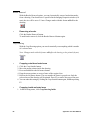
Border Removal
With the Border Removal option, you can electronically remove border/trim marks
from a drawing. If no border size is specified in the Imaging Properties window (0.0
mm), the size will be set to 2.5 mm. Changes made with this feature will affect the
drawing.
•
Removing a border
Click the Border Removal button.
To undo border removal, click the Border Removal button again.
Crop Drawing
With the Crop Drawing option, you can electronically erase anything which is outside
of a selected area.
Note: Changes made with this feature will affect the drawing or the printed (layout)
drawing.
•
1.
2.
3.
4.
5.
6.
•
Cropping outside selected area
Click the Crop Outside button.
Move the mouse pointer inside the drawing.
Press and hold down the left mouse button.
Drag the mouse pointer to create a frame of the required size.
Release the left mouse button. The area outside the frame is grayed-out. Only the
selected area of the drawing will be printed. Press F5 to remove the grayed-out part.
You can undo this setting by clicking the Crop Outside button again, and then pressing
F5.
Cropping inside selected area
1. In the Drawing menu, click Crop Drawing Inside.
$SSUHQWLFH8VHU0DQXDO
2.
3.
4.
5.
Move the mouse pointer inside the drawing.
Press and hold down the left mouse button.
Drag the mouse pointer to create a frame of the required size.
Release the left mouse button. The area inside the frame is grayed out. Only the
selected area of the drawing will be printed.
6. To undo this setting, click Crop Drawing Inside in the Drawing menu again.
Enlarge Detail
With the Enlarge detail option, you can select a part of a drawing to fit the size of the
paper selected.
Note: Changes made with this feature will affect the drawing or the printed (layout)
drawing.
•
1.
2.
3.
4.
5.
Creating a detail
Click the Detail button.
Move the mouse pointer to the drawing.
Press and hold down the left mouse button.
Move the mouse pointer to create a frame of the required size.
Release the left mouse button. The area inside the frame will be enlarged to fit the
selected paper size.
Note: To undo the enlargement, click the Detail button again and select the complete
drawing.
Edit Pen
With the Edit Pen option, you can edit the pen settings. You can change the thickness,
the pattern, or the effect of a particular pen in a drawing.
9LHZLQJ'UDZLQJV
•
1.
2.
3.
4.
5.
6.
Editing pens
Click the Edit Pen button.
Move the mouse pointer to the pen line that you want to change.
Click the left mouse button. The Pen window of the selected pen appears.
Change the required settings, such as line thickness, patterns, and foreground effect.
Click OK. The Job window appears, and you are asked whether you want to save the
changes you have just made.
Click Yes to save the changes. You will return to the View window.
Note: When you do not want to save the changes click NO. The changes will not be
used.
Center Drawing
With the Center Drawing option, you can center the drawing on paper in relation to
all four sides of the drawing.
Note: Changes made with these features will affect the drawing.
•
Centering a drawing
Click the Center Drawing button. The drawing is centered on the page.
Click the Center Drawing button again, and the drawing will be positioned as it was
originally, without any alignment (the alignment is defined as 0.0 x 0.0).
Align Title Block
With the Align Title Block button, you can align the drawing in relation to the top,
bottom, and right-hand edges of the selected paper size.
Note: Changes made with these features will affect the drawing.
•
Aligning the title block
Click the Align Title Block button.
To undo, click the Align Title Block button again. The drawing is placed in the upper
left corner of the paper.
$SSUHQWLFH8VHU0DQXDO
Mirror, Rotate Right, Rotate Left and Rotate 180
These tools are used to mirror a drawing for preparing blueprints, to rotate the
drawing clockwise or counter-clockwise, or to flip the drawing 180 degrees.
Note: Changes made with these features will affect the drawing.
0LUURUWith the Mirror button, you can reverse the information in the selected
drawing in order to produce a mirrored image.
5RWDWH5LJKWWith the Rotate Right button, you can rotate the drawing and paper
90 degrees in a clockwise direction.
5RWDWH/HIWWith the Rotate Left button, you can rotate the drawing and paper 90
degrees in a counter-clockwise direction.
5RWDWHWith the Flip Drawing button, you can rotate the drawing and paper
180 degrees.
•
Using the Mirror and Rotation buttons
Click the required rotation button. The drawing is rotated.
To undo the rotation, click the button again.
Negative Paper
With the Negative Paper button, you can reverse the background of the paper from
white to black. You can use this option to imitate DOS-based CAD systems.
Changes made with this feature will only affect the View mode. The actual drawing
is not affected.
•
Using the Negative Paper button
Click the Negative Paper button
To undo the Negative Paper function, click the button again.
9LHZLQJ'UDZLQJV
Rasterization
With the Rasterization mode, you can convert the image from a vector (line) image to
the raster image that will appear on paper, with all pen characteristics applied. This
shows you what a drawing will look like before it is printed on paper.
Note: Changes made with this feature will only affect the View mode. The actual
drawing is not affected.
•
Using the Rasterization button
Click the Rasterization button
To undo the Rasterization function, click the button again
Color Patterns
With the Color Pattern button, you can apply patterns to color lines. This slows
viewing and printing, but does not affect the source file.
•
Using the Color Pattern button
Click the Color Pattern button
To undo the color patterns, click the button again
Outline Polygons
With the Outline Polygons button, you can remove fills in polygons and polylines.
This can be helpful in determining whether a drawing was correctly prepared.
Note: Changes made with this feature will only affect the View mode. The actual
drawing is not affected.
•
Using the Outline Polygons button
Click the Outline Polygons button.
To undo the Outline Polygons function, click again.
$SSUHQWLFH8VHU0DQXDO
Status Bar
The status bar is located at the bottom of the Apprentice window. It allows you to
move through the drawings in a job list, to set the ruler type, and to change paper and
drawing attributes.
Previous/Next Drawing
You can use the Left and Right arrow buttons of the status bar at the bottom of the
Apprentice window, to scroll through the drawings in the job. This function only
works if all drawings are already opened in a viewer window.
Ruler
The Ruler button shows you the selected type of Viewer ruler. You can set the rulers
to measure in pixels, centimeters or millimeters.
•
Setting a type of ruler
1. Click the Ruler button. The Ruler menu appears.
2. Select the required unit:
• Inches
• Millimeters
• Centimeters
• Pixels
Drawing Size
The Drawing Size or Clipping button shows you the size of the current drawing or
clipping area.
•
Changing Drawing Size
1. Click the Drawing Size button. The Drawing Size menu appears.
2. Select the required option:
• Rotate Drawing - to rotate the drawing to the right, to the left or by 180 degrees
9LHZLQJ'UDZLQJV
• Crop Drawing - to crop the drawing inside or outside
• Alignment - to align Center Drawing or Align Title Block
• Border Removal
• Mirror Drawing
• Change Drawing Size
• Move Drawing
• Edit Pen Color
Zoom Status
The Zoom Status button shows you the current enlargement percentage.
•
Changing the Zoom Status
1. Click the Zoom Status button. The Zoom Status menu appears.
2. Select the required option:
• Fit: to fit to the page, to the width or to the height.
• Percentages
• Zoom In
• Zoom Out
• Zoom Select
Paper Size
The Paper Size button shows you the current paper size.
•
Changing Paper Size
1. Click the Paper Size button. The Paper Size menu appears.
2. Select the required option:
• Rotate Paper
This feature rotates the paper 90° (landscape orientation and portrait orientation).
• Set left margin
• Change paper size
• Enlarge detail
•
Setting a left margin for binding
1. After clicking on the paper size button, select Set Left Margin. When you move your
cursor over the drawing, it changes to a black arrow and vertical bar.
$SSUHQWLFH8VHU0DQXDO
2. In your drawing, place the vertical bar at the position where you want to set your left
margin. Use the rulers in order to position it accurately.
3. Click once. The space allocated to the left margin of your drawing is displayed as a
colored area.
Locator
The Locator box displays the coordinates of the current position of the pointer in the
viewer.
Second Locator
The second Locator box is only valid when a selected area has been zoomed or
cropped.
9LHZLQJ'UDZLQJV
Viewer Menu Bar
Some Viewer options are available only from the menu bar at the top of the screen.
3ULQWLQJIURPWKHYLHZHUChoose print from the File menu. This gives you access
to standard Apprentice printing options:
•
Exporting an EMF file
1. In the File menu, choose Export EMF File. The Export EMF File to... dialog box
appears.
2. Name your file and save it to the desired location. The file is saved as a extended
Windows metafile.
•
Copying to the clipboard
From the Edit menu, choose Copy to Clipboard. Your file is copied to the Windows
clipboard.
3DQ9LHZThe Pan View tool allows you to manually move the view across the
viewer. In contrast to the Move Drawing feature, this feature will not affect the
drawing. This command is very useful when you are zoomed-in on a drawing and
wish to move across the drawing without changing its position on paper.
•
1.
2.
3.
4.
Using the Pan View feature
From the View menu, choose Pan View. The mouse pointer changes to a hand.
Press and hold down the left mouse button.
Move the mouse pointer through the drawing to the desired position.
Release the mouse button.
8QGRDQG5HGRTo undo the last action, choose Undo from the Edit menu.
Choose Redo in order to reinstate an action which has previously been undone.
$SSUHQWLFH8VHU0DQXDO
Viewer Troubleshooting
This section provides some solutions to common problems you may experience when
using the viewer.
7KHYLHZHUZLOOQRWRSHQThe selected file may not be a supported vector or
raster file. Is there an icon next to the filename, or a question mark? If it is a question
mark, Apprentice does not recognize the file and it cannot be viewed.
7KHYLHZHURSHQVEXW\RXFDQQRWVHHWKHGUDZLQJThe positioning of the
drawing may be incorrect. First click Fit Page to view the entire drawing. You can
also try to use Center Drawing or Title Block Align to put the drawing on paper. If
the drawing does not appear to be correctly positioned on the paper, use Move
Drawing to manually position the drawing.
7KHYLHZHURSHQVEXWWKHVL]HRIWKHGUDZLQJLVWRRVPDOORUWRRODUJH
The size of the paper may be incorrect. Check paper size to ensure that it is correct.
9LHZLQJ'UDZLQJV
$SSUHQWLFH8VHU0DQXDO
$SSUHQWLFH
8VHU0DQXDO
Chapter 9
Imaging Properties
This chapter describes Imaging Properties tools that define the appearance of the drawing on the
paper.
Imaging Properties
You can define how each image will appear on paper. You can define settings for an
entire job, or change the settings of an individual file within a job.
•
Opening the Imaging Properties dialog box
1. In the Properties quick menu, click Imaging Properties. The Imaging Properties
dialog box appears with values for the selected file.
2. Click the arrows in the lower right corner to browse through the output properties of
all drawings in the job window.
Each setting is represented by a tab:
• Paper Size
• Drawing Size
• Alignment
• Border Removal
• Margins
• Zoom
• Orientation
• Folder
Paper Size tab
You can select the paper size in Imaging Properties. Increasing or decreasing the paper
size will not affect the size of the drawing, unless so specified.
In the Paper Size tab, you can define the following options:
$SSUHQWLFH8VHU0DQXDO
&KDQJHSDSHUVL]HIn the pull-down menu you can select a pre-defined standard
paper size.
Note: In the Paper Sizes tab of the Configuration dialog, you can specify paper sizes to
include in this window.
8VHU3DSHU6L]HIn the User Paper Size entry box, you can type custom sizes.
Note: If the selected paper size is not available, a warning will appear and you will be given
the option of printing on an available larger format.
0DNH3DSHU6L]HVDPHDV'UDZLQJ6L]HIf you select this option, the paper
size is scaled to fit to the drawing size.
Note: If the selected paper size is not available on the Océ 9700/9800, a warning will appear
and you will be given the option of printing on an available larger format.
Drawing Size tab
You can use the Drawing Size tab to clip a specific area from the original drawing.
The region outside will not be printed.
In the Drawing Size tab, you can define the following options:
6WDQGDUGGUDZLQJVL]HSelect a pre-defined standard drawing size from the list.
&OLSSLQJ6L]HTEnter a custom drawing size.
&OLSSLQJ8QLWVSelect inches or millimeters.
,PDJLQJ3URSHUWLHV
Alignment tab
You use the Alignment tab option to define the positioning of the drawing on the
paper.
In the Alignment tab, you can define the following options:
2IIVHWIURP8SSHU/HIWIn the Offset from Upper Left entry box, you can enter
width and height by typing in sizes. For example, when you want to add a 2-inch or
40-mm margin to the left side of the drawing, you could define a width alignment of
2 inches or 40 mm. When you want to add a 2-inch or 40-mm margin to the right side,
you could define an alignment of -2 inches or -40 mm.
6SHFLDO$OLJQPHQW2SWLRQVChoose one of the section options or choose Align
Title Block to position the drawing with an even margin along the top, bottom and
right-hand sides of the paper, so that the title block for each drawing will be even This
option might not work as expected if the drawing is rotated.
Border Removal tab
If you activate the Border Removal tab, the margins of the drawing will be
electronically erased. You can use this option to eliminate trim marks added by the
author of a drawing.
$SSUHQWLFH8VHU0DQXDO
In the Border Removal tab, you can choose:
• to remove the border
• the amount of border removal
• the unit of border removal: Inches, Millimeters, Centimeters or Pixels.
Margins tab
Using the Margins tab, you can add a margin to the left side of the drawing (default
is Off).
In the Margins tab, you can choose:
• to add a left margin
• the size of the left margin
• the unit in which to measure the left margin: Inches, Millimeters, Centimeters or
Pixels.
,PDJLQJ3URSHUWLHV
Zoom tab
On the Zoom tab, you can define custom enlargements and reductions.
In the Zoom tab, you can select:
=RRP%\6L]HIn the Zoom by Size entry box, you can define the width or the
height of the drawing. After one dimension has been selected, the other dimension
will be adapted proportionally.
=RRP%\3HUFHQWIn the Zoom by Percent entry box, you can define a scaling
percentage.
+RZ7R=RRPIn the How to Zoom entry box, you can choose not to have your plot
zoomed, or to have your plot zoomed by the percentage specified, or to have your
drawing zoomed to fit on the selected paper size.
Orientation tab
You can set the orientation of the paper and the way in which the drawing is printed
on the paper. You can see the effect of your selected options in the figure on the tab.
$SSUHQWLFH8VHU0DQXDO
You can select the following options:
• Portrait, Landscape or Free Fit
• Mirror
• Rotate 180°°
• Negative
)UHH)LWIf you select this option, you can apply the rotation and mirroring features
to the drawing without affecting the paper orientation. This allows you to give the
drawing an orientation different to that of the underlying paper.
Folder tab
If the job will be printed on a supported printer that is equipped with a folding unit,
you can specify Folder settings. You can save the settings in a file for future use.
Apprentice shows which part will be on top when you are creating the job.
,PDJLQJ3URSHUWLHV
$WWHQWLRQ,QWKH2SWLRQVPHQXGHVHOHFW$XWR3DSHU5RWDWH
)ROGHU2SWLRQVThe folding unit can be equipped with a number of options,
depending on the configuration you are using:
• Don’t Fold: Output will not be folded.
• Fold: Output will be folded without any options.
• Fold & Punch: Output will be folded and punched (if puncher installed).
• Fold & Reinforce: Output will be folded, and a reinforcement strip will be added (if
reinforcement unit installed).
• First Fold Exit: Output will only be folded in one direction (first fold), and then
delivered in the First Fold Delivery tray.
0HWKRGYou can specify one of the following folding methods: Standard, Ericsson
or Afnor.
)ROGLQJ6L]HYou can specify the Folding Width and Folding Height.
%LQGLQJ(GJHIf desired, you can select a Binding Edge, and specify the size of that
edge.
$SSUHQWLFH8VHU0DQXDO
$SSUHQWLFH
8VHU0DQXDO
Chapter 10
Setting Pen Parameters
This chapter describes how to define pen settings.
Pens
A pen controls the appearance of lines drawn by a customer.
• Pens apply only to vector files, not to raster files.
• Pen zero is used for raster files and for stamps (gray shading).
Apprentice can set pen weights (width), patterns, shapes, effects, and colors. This
allows you to customize the appearance of your customer’s drawings. Apprentice can
create, save, and store an infinite number of pen sets.
When a job is opened, Apprentice will apply a pen set called STANDARD.PEN. This
pen set is employed for day-to-day use. You can view the pen settings, using the Pen
set icon on the button bar. The Pen settings window appears.
STANDARD.PEN is installed at the time of installation of Apprentice. Pen settings
need to be customized only once. When you transmit your jobs for printing, your
personal settings will be applied to every job you send.
When you open a new pen set, it always has the following default attributes:
• solid black pens
• .25 millimeters wide, for all pens
• transparent lines
• colors used are the same as in the AutoCAD palette.
If you want to change these attributes, use the following procedure.
$SSUHQWLFH8VHU0DQXDO
•
1.
2.
3.
4.
5.
Creating a pen set
Select the drawing for which the pen settings need to be changed.
In the toolbar, click Pen Set. The Pen Settings window appears.
Click a pen number to select it.
In the toolbar, click Properties. The Pen Properties dialog box appears.
Change properties as needed and click Apply.
The Pen Properties dialog box contains the following tabs:
• patterns
• width
• shape
• effect
• all pens
• edit pattern
• controls
1RWH The scroll bar at the right-hand side of the Properties Sheet allows you to move quickly
to other pens in the set.
Pen Patterns
You can select from 119 different pen patterns. These patterns fall into three broad
categories:
• Gray-scale patterns: Patterns used for achieving a percentage of black. These
patterns are commonly used in filled areas of a drawing.
• Active patterns: Patterns that change direction, depending on the line curve.
• Miscellaneous patterns such as boxes, tiles, slants, diamonds, etc.
6HWWLQJ3HQ3DUDPHWHUV
You can define the shade of gray with the slider bar, and by clicking on a pattern box.
•
1.
2.
3.
4.
•
Selecting the gray shade
In the Pen Properties dialog box, click the Patterns tab.
Click and hold the slider in the halftone slider bar.
Drag the slider to the desired gray shade and release the mouse button.
Click Apply.
Selecting the pattern
1. In the Pen Properties dialog box, click the Patterns tab.
2. Click the desired pattern to select it.
3. Click Apply.
1RWH To view all patterns, use the scroll bar in the select pattern section.
Pen Width
You can set pen widths from 0 to 40 pixels. Apprentice uses pixels, millimeters, mils
(1/1000 inch), and centimeters for pen weights. Because pens are measured by pixels
(dots), measurement is limited. If it is necessary to round off pen thicknesses, it is best
to consult with the author of a drawing.
$SSUHQWLFH8VHU0DQXDO
Pen Shape
A pen’s shape refers to the shape of the pen tip. You can select from:
• Round ended
• Square ended
• Butt ended
Effect
A pen’s effect refers to the appearance produced by a pen when it crosses another pen.
A pen’s effect can be:
• Transparent (default). Pens overlay each other without either of them blocking the
appearance of the other line. Where lines intersect in the viewer, the colors merge.
• Opaque. An opaque line will display on top of another line that is lighter in color.
Thus, only the darker color line is visible.
• Xor. An Xor line will display on top of another line that is darker in color. This effect
is only visible when you print to a color printer.
6HWWLQJ3HQ3DUDPHWHUV
All Pens
On the All Pens tab, you can make settings for the whole pen set.
On the All Pens tab, you can define:
6FDOH3HQ:LGWKThis option applies when changes are made to scale. If you are
preparing reductions or enlargements, you have the option of having Apprentice
automatically change the widths of the pens along with the length of the lines. The
default setting is used to change the pen scale when changes in scale are made to the
drawing.
*OREDO3HQ:LGWKVYou can set the minimum and maximum pen widths which
will be allowed in a drawing. The default minimum pen width is 0 pixels, and the
default maximum is 40 pixels.
3HQ:LGWK8QLWVYou can choose to display pen widths in inches, pixels,
millimeters and centimeters.
$SSUHQWLFH8VHU0DQXDO
1XPEHURI3HQVApprentice supports up to 255 pens (and pen 0). You can reduce
the number of pens in a pen set. The default setting is 255 pens.
Edit Pen Pattern
Apart from the 119 pre-defined pen patterns from which you can choose, Apprentice
allows you to create your own custom set pattern.
You can use the following options to create a custom pattern:
3DWWHUQ9LHZHUUse the mouse to click pixels in the viewer On or Off. The left
mouse button turns a pixel black; the right-hand mouse button turns a pixel white.
This viewer measures 32 pixels by 32 pixels.
3DWWHUQ6L]HA grid divides the viewer into sections. Changes made in one section
of the grid are copied to corresponding sections. This ensures uniformity in new
custom patterns.
8QGR5HGRErases or redraws changes made in the pattern viewer.
,QYHUWReverses the image in the pattern viewer, so that white pixels become black
and black pixels become white.
1DPHGive the pattern a name. This name will be displayed when the pen set is
open.
3DWWHUQQXPEHUAllows you to select one of the 255 patterns to edit. If you are
creating a new pattern, use a pattern number above 200.
$UURZVAre used to adjust the position of the pattern within a grid.
)LOO$OO:KLWHFills the selected pattern grid with white pixels.
6HWWLQJ3HQ3DUDPHWHUV
)LOO$OO%ODFNFills the selected pattern grid with black pixels.
6DYH(QWLUH6HWSaves the set of patterns. Apprentice installs a default set of
patterns called DEFAULT.SET. If you wish to add patterns to your set, save the set
using the same name.
1RWH Make sure you do not overwrite existing patterns 1 through 200, because remote users
will be using the DEFAULT.SET as well. If they request a default pattern that you have
changed and which they do not have, their drawings will be incorrect. If you are creating a
special set of patterns, save the set under a different name.
/RDG1HZ6HWUsed to load a complete set of patterns.
6DYH3HQ3DWWHUQSaves an individual pattern. This is useful for remote customers
who create a few individual patterns. This will save only an individual pattern. If a
person has a special pattern, they should save it. This pattern can be added to a JOB
and sent by modem, network, or diskette. The author of the drawing will have to tell
you to which pen(s) the new pattern applies.
/RDG3HQ3DWWHUQUsed to load an individual pattern. If the pattern is to be re-used,
it can be added as a pen pattern to the DEFAULT pen set. If you decide to add a single
pattern to this set, be sure to save it above pattern 200.
$SSUHQWLFH8VHU0DQXDO
Pen Controls
This tab applies to HP-GL/2 files and files created with the VIC24.pc3 driver.
In HP-GL/2 files and files created with the VIC24.pc3 driver, pen attributes such as
width, color and so on are built into the plot file. This tab allows you to use the pen
attributes set in the file, rather than the Apprentice pen settings. For HP-GL/2 files
and files created with the VIC24.pc3 select the following check boxes:
3HQ:LGWKVCheck this option to use the pen width sizes that have been defined in
the file.
3HQ&RORUVCheck this option to use the pen colors that have been defined in the
file.
)LOO6FUHHQVDQG3DWWHUQVCheck this option to use the area fill halftone screens
and fill patterns that have been defined in the file.
3HQ6FUHHQVDQG3DWWHUQVCheck this option to use the pen halftone screens and
pen patterns that have been defined in the file.
3HQ(IIHFW7UDQVSDUHQF\Check this option to use the transparency settings
defined in the file.
6HWWLQJ3HQ3DUDPHWHUV
The following options are also available on this tab. Deselect the following check
boxes for files created with the VIC24.pc3; they are optional for HP-GL/2 files:
0DS3HQ&RORUVWRD6KDGHG+DOIWRQHselect this check box to map colors to
different levels of gray-scale when you are using a color file to print to a monochrome
printer.
8VH$OWHUQDWH)LOOVLQVWHDGRI:LQGLQJ)LOOVSelect this check box to change
the behavior that is used to fill polygons in vector files. In general, the modes differ
only in cases where a complex, overlapping polygon must be filled (for example, a
five-sided polygon that forms a five-pointed star with a pentagon in the center). In
such cases, Alternate Mode fills every other enclosed region within the polygon (that
is, the points of the star), but Winding Mode fills all regions (that is, the points and the
pentagon).
'R1276FDOH+357/5DVWHU'DWDSelect this check box for use with
HP-RTL Raster Data. HP-RTL is a special format of HP-GL that allows inclusion of
raster data within the vector data. However, if such files are scaled, the raster data will
become very chunky, due to the nature of raster data. Selecting this option prevents
the raster part of the drawing from being scaled.
8VH(UURU'LIIXVLRQIRU*UD\RU&RORU57/LPDJHVSelect this check box to
affect shades of gray in RTL raster data. Apprentice employs Halftone Diffusion by
default. You may want to use Error Diffusion instead to improve the appearance of
your image.
$SSUHQWLFH8VHU0DQXDO
Modifying Pen Features
You can modify the pen parameters directly in the Standard.pen window, although
this is not recommended. Instead, you are encouraged to create a new pen set, as
described in‘Creating a pen set’ on page 105.
•
Modifying a pen attribute
1. Open the job window with the required drawings.
2. In the toolbar, click Pen Set. The standard pen set window appears.
Right-click the column heading for the field you want to modify. A menu appears.
You can also select one of the following options in each column:
3URSHUWLHVTo select the Pen property window.
&RS\$OOTo copy the attribute setting to all pens.
&RS\'RZQTo copy the attribute setting to all pens below the one highlighted.
You can de-select a pen by clicking on the indicator in front of the pen set. The pen
will be crossed through with a red line.
6HWWLQJ3HQ3DUDPHWHUV
You can define the color of the pen.
•
1.
2.
3.
4.
5.
Defining the color of a pen
In the toolbar, click Pen Set. The standard pen set window appears.
Double-click the color attribute of the pen you want to modify. The color palette
appear.
Click the Define Custom Colors tab. The color palette expands.
Type or select the desired RGB values, hue, saturation and luminance.
Click Add to Custom Colors, then click OK.
$SSUHQWLFH8VHU0DQXDO
$SSUHQWLFH
8VHU0DQXDO
Chapter 11
Defining Stamps and Overlays
This chapter describes how to make stamps and use overlays.
Electronic Stamps
An Electronic Stamp contains text that is to be overlaid on drawings or on empty
pages to create banners.
•
Creating or changing an electronic stamp
1. In the toolbar, click Stamp. The Electronic Stamp window opens.
2. Click Browse and navigate to an existing stamp for editing, or begin creating a new
one, with the Stamp tab features. See the following sections.
3. Click OK. For a new stamp, you specify a name and directory for storage.
• If you want to add the new stamp to the current job, click OK. The Stamp Properties
window disappears, and the stamp will automatically be added to the current job (if
any).
• If you do not want to add the new stamp to the current job, click Cancel. The Stamp
Properties window disappears, and you can add the stamp to a job later.
Stamp options
The Stamp Properties dialog box contains the following elements:
3UHYLHZZLQGRZThe Preview window shows how changes such as font, rotation
and spacing will affect your text .
$SSUHQWLFH8VHU0DQXDO
(QWHU7H[W:LQGRZThe text used for the label is displayed in this window as plain
text.
6WDPSLQJ2SWLRQVZLQGRZClick the appropriate check box to add such
information as date, time, project and filename, page and set number. Apprentice
reads it directly from your computer system, so that when you print the stamp or label
you have the current date, time and filename. This information is displayed in the
Enter Text window.
Note: If you have selected the File Name option and the drawing is processed, the drawing’s
original path is displayed in the stamp. Otherwise, it shows only the filename without the path.
)RQW3URSHUWLHVClick Choose Font to open the font dialog box, where you can
change the type, size and style of the font. The current font settings are displayed in
the Font Sample field.
&KDUDFWHU5RWDWLRQRotates the letters and the baseline to change text orientation.
Use the Up arrow to rotate the text clockwise and use the Down arrow to rotate the
text counter-clockwise.
%DVHOLQH5RWDWLRQRotates the baseline only. Use the Up arrow to rotate the
baseline counter-clockwise and use the Down arrow to rotate the text clockwise.
&KDUDFWHU6SDFLQJUse the Up arrow to increase the space between two
characters; use the Down arrow to decrease the space between two characters.
/LQH6SDFLQJUse the Up arrow to increase the space between two lines; use the
Down arrow to decrease the space between two lines in lines of text.
3DWWHUQYou can choose a pattern to fill the characters
7UDQVSDUHQWIf you select this option, underlying information on the drawing will
stay visible, depending on the used pattern, grayscale or color.
)LOOHGWH[WIf you select this option, characters are filled. Default solid black will be
used to fill the characters, but you can also choose a pattern (see above).
If this option is not selected, outline characters will be used.
Note: The color of the stamp is determined by pen 0 of the default pen set.
Position options
In the Position window, you can specify how the stamp should be positioned on the
paper (Align Top, Align Left, Bottom Right, etc.) The viewer might show the stamp
'HILQLQJ6WDPSVDQG2YHUOD\V
in one location, but the stamp will print relative to how the paper comes out of the
printer.
Note: After adding the stamp to a drawing in a job, you can also use the viewer to position
the stamp on a drawing.
The Position window contains the following elements:
,QLWLDO3ODFHPHQWYou can select one of the standard positions for the stamp on the
paper.
)LQH7XQLQJAfter selecting a standard stamp placement, you can specify small
adjustments to move or rotate the stamp on the paper.
Adding a stamp to a drawing
After creating and saving, you can add a stamp to a drawing.
•
Adding a stamp to a drawing
1 Open the job that contains the desired drawing.
2. Right-click the drawing to which you want to add the stamp. A menu appears.
3. Click Add Overlay. The Add Overlay To Drawing window appears.
4. Type the file name of the stamp you want to add, and click Open. In the job window,
the stamp name is indented and added to the base drawing.
Adding a stamp to all drawings
You can add the same stamp to all drawings in a job.
$SSUHQWLFH8VHU0DQXDO
•
Adding a stamp to all drawings
1 Add a stamp to one drawing using the procedure in the previous section.
2. In the job window, right-click the stamp name. A menu appears.
3. From the menu, choose Copy All Overlay. The stamp is added to all drawings in the
job.
Overlaying files
An electronic overlay is created when one electronic drawing file is placed on top of
a second electronic drawing file. The two drawings are printed out on one and the
same piece of paper, with the overlay drawing superimposed over the base drawing.
You can overlay drawing files and stamps.
•
1
2.
3.
4.
Adding an overlay
Open the job that contains the desired drawing.
Click on the drawing to which you want to add the overlay with the right-hand mouse
button. A drop-down window appears.
Select Add Overlay. The Add Overlay to Drawing window appears.
Type the file name of the overlay you want to add and click Open. In the job window,
the stamp (slightly indented) is added to the base drawing.
'HILQLQJ6WDPSVDQG2YHUOD\V
Viewing and Positioning
You can use the viewer to see the result of adding stamps and overlays to a drawing
or to change the stamp position and see the result immediately.
•
Viewing a drawing with added stamp or overlay
1 In the job window, double-click the added stamp or overlay.
The View window appears to display how the stamp or overlay is added to the
drawing.
•
Positioning a stamp or overlay in the viewer
1 Open the drawing and the added stamp or overlay in the viewer, as described in the
previous section.
2. Click
in the viewer toolbar.
3. Click the stamp you want to move, then press and hold the mouse button while
moving the stamp or overlay. You can see the result immediately in the View window.
$SSUHQWLFH8VHU0DQXDO
$SSUHQWLFH
8VHU0DQXDO
Chapter 12
Sending Jobs
This chapter describes how to send jobs via modem, queue, e-mail, or file on diskette, and how
to prepare a work order.
Introduction
When you are ready to have your final drawings printed, there are several ways of
sending your work. For each method, Apprentice sends the correct pen set and other
settings along with a work order.
Sending jobs or files to ProjectPoint™ sites
When you send files to a ProjectPoint site, you can share them with anyone who has
a password to that site. You can send an entire job, or a single drawing.
6HQGLQJMREVWR3URMHFW3RLQWVLWHV
With the job window active, choose one of these methods to access the dialog box:
•
1. In the Send Job quick menu, click Send Job To...
OR
1. In the toolbar, click Send Job.
OR
1. Right-click the drawing name. A menu appears. Click Send Entire Job To... A
submenu appears. Click ProjectPoint
The Send Job To dialog box appears.:
2. Select the ProjectPoint radio button.
3. Select a project from the list and click OK or click Select to navigate to the desired
site. The work order appears.
$SSUHQWLFH8VHU0DQXDO
4. Fill out the work order as described elsewhere in this chapter. After you click Submit,
the order receipt and Add to ProjectPoint wizard appear.
5. Follow the steps in the wizard.
6. Click Finish. The job is sent to the ProjectPoint site.
7. Click Print to print the order receipt or click Close to close it without printing.
•
1.
2.
3.
4.
5.
6HQGLQJDVLQJOHGUDZLQJWRD3URMHFW3RLQWVLWH
Right-click the drawing name. A menu appears.
Click Send Single Drawing To... A submenu appears.
Click ProjectPoint. The ProjectPoint wizard appears.
Follow the steps in the wizard.
After you click Finish, the selected drawing is sent.
Sending a job to a network queue
You can send your job directly to a network queue for attended or unattended printing.
•
6HQGLQJMREVWRDQHWZRUNTXHXH
1. In the toolbar, click Send Job. The Send Job To... dialog box appears.
2. Select the Queue radio button.
3. Select the desired path from the drop-down list or click Browse to navigate to a
different location.
4. Click OK. The Send Job window displays the work order.
5. Fill out the work order as described later in this chapter.
Sending a job by modem or FTP
If you have a modem and you have installed and configured ApModem or ApFTP, you
can send your drawings using a configured communication method.
6HQGLQJ-REV
6HQGLQJDMREYLDPRGHP
1. In the toolbar, click Send Job. The Send Job To... dialog box appears.
•
2. Select the Modem radio button.
3. From the list, choose the appropriate communications method. If the item you need is
not in the list, see the following section, Adding a Communications Method.
4. In the Send Job To... dialog box, click OK. The Send Job window displays the work
order.
5. Fill out the work order as described later in this chapter.
$GGLQJDFRPPXQLFDWLRQVPHWKRG
1. In the Send Job To... dialog box, click Modem, then click New. The Add
Communications Method dialog box appears.
•
2. Type information in the fields as needed or click Browse to navigate to the required
communication executable (for example, ApModem32.exe). Method Name and
Executable are required fields.
3. Click OK to return to the Send Job To... dialog box with the newly added method now
in the list.
4. In the Send Job To... dialog box, click OK. The Send Job window displays the work
order.
$SSUHQWLFH8VHU0DQXDO
5. Fill out the work order as described later in this chapter.
Sending a job to be stored on disk
You can save your job onto a hard drive or floppy disks to take to your job printer.
•
6HQGLQJDMREWREHVWRUHGRQGLVN
1. In the toolbar, click Send Job. The Send Job To... dialog box appears
.
2. Select the Drive radio button and the Drive Letter from the drop-down list.
Note: Any previous jobs with the same name will be overwritten.
3. Click OK. The Send Job window displays the work order.
4. Fill out the work order as described later in this chapter.
Sending a job by e-mail
You can e-mail a job to someone if you have MAPI-compliant e-mail installed.
•
1.
2.
3.
4.
5.
6.
6HQGLQJDMREE\HPDLOZLWKRXWDZRUNRUGHU
In the job window, right-click any drawing within the job. A menu appears.
In the menu, click Send Entire Job To. A submenu appears.
Click E-mail recipient. The e-mail message dialog box appears with the job attached
as a .zip file.
If necessary, change the name of the .zip file. It will overwrite any previously saved
.zip files with the same name.
In the body of the e-mail, add print order instructions.
In the header of the e-mail, type a recipient name and click Send.
6HQGLQJ-REV
•
1.
2.
3.
4.
5.
6.
7.
8.
6HQGLQJDMREE\HPDLOZLWKDZRUNRUGHU
Follow the directions for sending to a drive. See ‘Sending a job to be stored on disk’
on page 125.
In Windows Explorer, navigate to the job on the drive.
Right-click the job. A menu appears.
Click Send To. A submenu appears.
Click Mail recipient. The e-mail message dialog box appears with the job attached as
a .zip file.
If necessary, change the name of the .zip file.
In the body of the e-mail, add print order instructions.
In the header of the e-mail type a recipient name and click Send.
$SSUHQWLFH8VHU0DQXDO
Filling Out a Work Order
An electronic work order is automatically attached to your job when you send it. This
work order, also known as a job ticket, contains information identifying you and your
company, and detailed instructions for the job printer about how your job should be
processed, delivered, and billed.
Using the Work Order
Required fields are determined by the person who designs the work order in
Apprentice Server’s Work Order Customizer. Required fields appear in boldface type.
If they are not filled out, the job will not be sent.
&RPSDQ\Type the name of your company.
&RQWDFWType the name of the person whom the job printer should contact for
further information about the job being sent.
(PDLO$GGUHVVType an e-mail address where the contact person can be reached.
3KRQH1XPEHUType a phone number where the contact person can be reached.
3KRQH1XPEHUType any additional phone number for the contact person.
)D[1XPEHUType the company or department fax number.
$FFRXQW1XPEHUType your account number with the job printer.
6HQGLQJ-REV
'HOLYHU\$GGUHVV&LW\6WDWH&RXQWU\3RVWDO&RGHType the address
to which prints of this job should be delivered.
6SOLW$GGUHVV&LW\6WDWH&RXQWU\3RVWDO&RGHIf the delivery is to be
made to more than one site, type the other address here.
%LOOLQJ$GGUHVV&LW\6WDWH&RXQWU\3RVWDO&RGHType the address to
which bills for this job should be sent.
&RQWDFWLQIRUPDWLRQType any additional information about the contact person.
3URMHFWType the name of the project.
321XPEHUType your Purchase Order number.
'HOLYHU\0HWKRGFrom the list, select the way you would like to have your prints
delivered.
5HLPEXUVDEOHIf the printing costs are reimbursable, select the check box.
5HDVRQFrom the list, select the category for the reimbursement.
-RE'XH'DWHFrom the lists, select the month, day, and year you would like the
job to be delivered.
-RE'XH7LPHFrom the drop down lists, select the hour you would like the job to
be delivered.
6HW&RXQWChoose Use Set Information to use information from the next five
fields or choose Use Copies Field to use information from the job. If you choose Use
Copies Field, Apprentice will ignore any information in the First Set and Additional
Set Media, Edging and Count fields.
$SSUHQWLFH8VHU0DQXDO
)LUVW6HW0HGLDFrom the list box, select the type of media on which the first set
should be printed.
)LUVW6HW(GJLQJFrom the list box, select the type of edging with which the first
set should be bound.
$GGLWLRQDO6HW0HGLDFrom the list box, select the type of media on which
additional sets should printed.
$GGLWLRQDO6HW(GJLQJFrom the list box, select the type of edging with which
additional sets should be bound.
$GGLWLRQDO6HW&RXQWType the number of additional sets you require.
$UFKLYH-RE"Indicate whether the job printer should archive the job you are
sending.
-RE,QVWUXFWLRQVType any further instructions for the job printer here.
Electronic Media Format
Select the format in which you want electronic files to be delivered: PC or Macintosh.
'U\PRXQW-RESelect the Drymount check box if you want your prints to be
mounted.You can add instructions for specs, trim or edging.
/DPLQDWH-RESelect the Laminate check box if you want your prints to be
laminated. You can select the Both Sides check box or enter laminate specifications.
)LQLVKLQJ,QVWUXFWLRQVType any further instructions for the job printer.
6HQGDXWR(0DLOQRWLILFDWLRQZKHQWKLVMRESelect any combination of:
6HQGLQJ-REV
• Is received
• Is printed
• Has an error.
6XEPLWClick Submit to send the job and the work order.
&DQFHOClick Cancel to return to the job window without sending the job.
$SSUHQWLFH8VHU0DQXDO
Using the Order Receipt
The order receipt allows you to save information from the work order in your own
format.
•
'LVSOD\LQJVHOHFWLRQV
1. From the Send Job window, select any combination of the following check boxes:
• Contact
• Job
• Finishing
• Other Finishing
• Drawings List
2. The selected sections display.
6HQGLQJ-REV
3. Click Close to close the Order Receipt without printing, or click Print to print the
selected sections of the Order Receipt.
$SSUHQWLFH8VHU0DQXDO
$SSUHQWLFH
8VHU0DQXDO
Chapter 13
Publishing drawings
This chapter describes how to have Apprentice convert jobs to LDF files and post them at Plans
& Specs™ Online Service.
Introduction
After you have processed your drawings and they are print-ready, you can publish
them directly to a reprographer’s digital plan room at Plans & Specs™ Online
Service. You must be a registered buzzsaw.com user, and the reprographer must have
sent you an e-mail invitation to use a container structure.
Publishing drawings means converting them to the print-ready Layered Document
Format™ and putting them in the Plans & Specs system. It is different than processing
drawings, which means converting them to the vic format, and sending drawings,
which means transferring the vic files via LAN, modem, diskette, ISDN or e-mail.
For more information about Plans & Specs Online Service, visit www.buzzsaw.com.
$SSUHQWLFH8VHU0DQXDO
Creating LDF Files
Layered Document Format™ (LDF™) is a new file format used by the Plans &
Specs™ Document Management System. You can click the Publish button in the
Apprentice toolbar to convert all drawing files in an active job into LDF files. Then
you can publish them to a container structure at Plans & Specs Online Service.
3XEOLVKLQJGUDZLQJV
Adding LDF Files to Jobs
LDF files can be added to Apprentice job files for printing if you have an LDF file
print code. A logo to the left of a file name in a job window represents an LDF file.
OGIMREWLI
•
Adding an LDF file to a job
1. In the toolbar, click Add Files. The Add or Insert Drawing(s) dialog box appears.
2. Navigate to the drawing you want to add. Click it to select it.
Note: You can select more than one filename, by holding down the Ctrl button or the Shift
button (for a range of files), while selecting the filename.
3 Click OK. The drawing files are added to the job.
For more information about LDF file properties, see ‘About LDF Files’ on page 77.
$SSUHQWLFH8VHU0DQXDO
About the Plans & Specs Online Service
With Plans & Specs™ Online Service, customers can view WYSIWYG drawings that
are stored as LDF files and order prints from reprographers. The full Plans & Specs
application consists of two parts:
• Online Service, a Web-based application at www.buzzsaw.com
• DocServer, a Windows-based application that runs on reprographers' local servers.
Additionally, Autodesk offers several drivers, utilities and tools that work with the
main parts of the Plans & Specs system.
Both parts of the Plans & Specs application are based on the following container
structure:
Vaults
Each vault represents a reprographer’s electronic storefonrt.
Accounts
Each account represents a reprographer's customer.
Clients
Each client represents a customer of the account.
Projects
Each project belongs to no more than one client; an individual client can have multiple
projects, each with separate users and administrators.
3XEOLVKLQJGUDZLQJV
Issues
Issues represent a collection, subset or group of
documents for a stage of a project.
Disciplines
A discipline represents a functional or practical
subset of an issue, such as electrical or plumbing.
Documents
The plans and specs, or drawings, affiliated
with a project or issue.
$SSUHQWLFH8VHU0DQXDO
Publishing to Plans & Specs
You can process drawings in Apprentice into LDF files, then send them to your
reprographer’s Plans & Specs™ Online Service vault. The reprographer can then
synchronize the documents to the shop’s servers and print your order.
You must have the WebExchange functionality installed. The file bzwebxg.dll is
installed with Apprentice. This file must be registered using regsvr32.exe.
•
Sending jobs to Plans & Specs Online Service
1. Open the job containing the files you wish to send.
2. In the toolbar, click Publish.
3. The conversion progress bar shows the conversion progress, then the Plans&Specs
Logon message appears.
4. Click Log On. The Login dialog box appears.
5. Enter your buzzsaw.com user name and password and the container location for your
reprographer.
6. Click OK. The Plans & Specs Navigation dialog box appears.
7. Click Take you to the last issue used or Let you navigate on your own, then click
OK. The Plans & Specs system publishing wizard step 1appears:
8. In the tree view, click the plus sign for each container level to show subcontainers
OR
In the browser window, double-click each container icon to show subcontainers.
Navigate to the issue in which you wish to publish the documents.
9. Open the issue.
3XEOLVKLQJGUDZLQJV
10. If the issue is empty, the Add File button becomes available. Click Add File.
OR
If the issue contains documents, several buttons become available. Click a document
to select it, then click:
New File After to publish your Apprentice documents behind the selected file.
New File Before to publish your Apprentice documents in front of the selected file.
Republish to publish your Apprentice documents over the existing file.
The Publish LDF file dialog box appears:
11. Double-click any field for any document to enter new information. Press Enter on the
keyboard to save the new information:
12. Click Publish. A confirmation message appears. The documents are published to
Plans & Specs.
$SSUHQWLFH8VHU0DQXDO
$SSUHQWLFH
8VHU0DQXDO
Chapter 14
Queues
This chapter describes how to create and configure queues.
Introduction
The main purpose of a queue on Apprentice Server is to receive jobs that are sent by
remote clients. A queue keeps track of all the contents -- drawing files, stamps,
overlays, pen sets, work order -- for each job.
You can create a separate queue for each client, or different types of queues for various
clients.
,QFRPLQJTXHXHAn incoming queue collects jobs from remote clients. Apprentice
can be configured to automatically scan a queue for incoming jobs and to flash when
one arrives. You can also print the work order for each incoming job automatically on
a Windows printer.
Note: Apprentice will search for new jobs only when the queue is open. Generally, a queue should
remain open at all times.
If you know you have just received a job and do not want to wait for the queue’s next
scan cycle, you can press the F5 key to instruct the queue to search immediately.
$UFKLYHTXHXHQueues can also be used for archiving purposes, or to hold jobs you
might need to print again. You can move files from the incoming queue and store them
in another location. If the incoming and archive queues are both open, you can drag
and drop jobs between them. You can also send jobs to an archive queue by using the
Send Job To dialog box.
6SHFLDOSULQWTXHXHSpecial configured queues can be used for automatic
printing, direct printing, and printing native drawings (using polling queues).
0RGHPVKDULQJApprentice Remote clients can use a queue to share a single
modem. This allows different workstations to submit their jobs over one modem
connection. Remote clients must select the Automatically Modem Jobs check box in
the Options menu when you are in queue mode. When the shared queue detects a new
job, it will automatically launch ApModem, log in to the configured Apprentice
Server, transfer the job, and log off again.
$SSUHQWLFH8VHU0DQXDO
Creating an Incoming Queue
You can use the Queue Creation Wizard to create a new queue.
•
Creating an incoming queue
1. In the Queue quick menu, click Create New Queue. The Queue Creation Wizard Step 1 window appears:
2. Select the drive where the new queue will reside, and click Next. The Queue Creation
Wizard - Step 2 window appears:
3. Delete any text in the text box.
4. Specify the complete path and name of the new queue directory (for example,
INCOMING\QUEUE1), and click Next. The Queue Creation Wizard - Step 3
window appears:
4XHXHV
5. Delete any text in the text box.
6. Specify only the name of the queue (for example, Queue1), and click Next. The
Queue Creation Wizard - Step 4 window appears:
7. Select the Flash the Queue and Scan for New Jobs check boxes.
8. Click Finish. The Queue window of the new queue appears.
$SSUHQWLFH8VHU0DQXDO
Queue Options
When a queue is open, you are in queue mode and can click Options in the menu bar
to adjust settings. chapter 17, ‘Unattended Printing’ on page 201 for information on
setting up automatic and broadcast queues.
$XWRPDWLFDOO\3ULQW-REV(Default: off). Prints jobs on the selected printer as
they appear in the queue, without user intervention. In this case, they will not be
displayed in the queue.
$XWRPDWLFDOO\0RGHP-REV(Default: off). Transmits any received jobs in the
active queue by modem.
$XWRPDWLFDOO\3ULQW5HSRUW(Default: off) Prints the work order for each
arriving job on your local Windows printerApprentice
$XWRPDWLFDOO\$UFKLYH$IWHU3ULQWLQJ(Default: off). Copies a job into the
Archive queue when a job is printed or sent via modem or FTP. The Archive queue is
located in a sub-directory ARCHIVE.
$XWRPDWLFDOO\6FDQIRU1HZ-REV(Default: On). Searches for new files at
regular intervals (Default: every 30 seconds). You can manually scan for new jobs by
pressing the F5 button on the keyboard.
)ODVK4XHXHZKHQQHZMREVDUULYH(Default: on). The queue window will
flash black and white to alert the operator when new jobs arrive in the queue. (Do not
use this option in combination with Automatically Print Jobs or Automatically
Modem Jobs.)
6KRZ4XHXHZKHQQHZMREVDUULYHIf you have a minimized queue window
and a new job arrives, this option will force the queue window open.
6DYH4XHXH6HWWLQJV1RZ(Default: off). Saves the current queue settings to the
current queue. Opening and closing the queue will preserve the settings.
6FDQ1RZSearches manually for new jobs to print. You can also use the F5 button
to activate this option.
4XHXHV
Queue Information
Jobs received in a queue may have the following information:
• Job Name: Name of the file.
• Company: The name of the company that sent the job.
• Created: The date the job was received in the queue.
• Date Due: The date by which the job should be ready.
• Last Printed: The date when the job was last printed from the queue.
• Sets: The number of sets required.
• Sheets: The quantity of sheets of media used by Apprentice to complete the job.
• Comment: (appears for Apprentice Server only) Comments added by the
Apprentice operator.
-RE,FRQVAn icon appears to the left of the job name to indicate the status of the
job:
Sheet with star: This job has been added to the queue recently, and has not yet been
opened.
Simple sheet: This job has been opened but not yet printed.
Printer: This job has already been printed.
Disk: This icon indicates that the customer has requested that this job be archived.
•
1.
2.
3.
4.
Adding a comment about the job
Right-click the icon of the job. A menu appears.
From the menu, choose Comment Field. The Edit Comment Field dialog box
appears.
Type your comments in the comment box.
Click OK. Your comments are displayed in the queue window.
$SSUHQWLFH8VHU0DQXDO
Handling Queues
Queues can be a powerful tool to organize your daily work. the following sections
describe how to use them.
Opening queues
•
Opening a queue
1. From the queue menu, choose Open Queue. The View Existing Print Queue window
opens.
2. Select the required directory, path and filename.
3. Click OK.
Saving queues
Queues should be saved at the location where your communications software receives
files, or where your network users would expect to find the queue. Apprentice systems
have a default Incoming Queue called INCOMING.Q.
•
Saving a newly created queue
1. From the File menu, choose Save As. The Save As dialog box appears.
2. Select the drive and directory where you wish to save the queue, and click OK.
Receiving new jobs in a queue
Jobs are automatically numbered as they arrive, so that you can see the order in which
they came in. An incoming queue scans for new jobs arriving by modem, disk or
network every 30 seconds by default.
If you know a job has arrived on your computer and you want to display it in your
queue window immediately, press the F5 key on your keyboard or choose Scan Now
from the Options menu.
Working with queues
To add or organize jobs in a queue, the queue window must be active.
4XHXHV
•
Opening a job from the queue
1. Double-click the job. The selected job opens in a job window.
You can now view, modify, and print the job.
•
1.
2.
3.
4.
•
Adding jobs to the queue
From the Edit menu, choose Add Job File. The Add Job or Queue File to Queue
window opens.
Navigate to the location of the job you wish to add.
Select the job to be added to the Queue. The job is highlighted.
Click OK. The job is added to the queue.
Adding jobs from ProjectPoint™ sites
Choose one of the following methods for the first step, then go to Step 2.
1. Right-click the job name. A submenu appears. Click Add Job From ProjectPoint.
The ProjectPoint login appears.
OR
1. In the File menu, click Add Job From ProjectPoint. The ProjectPoint login appears.
OR
1. In the Queue quick menu, click Add Job From ProjectPoint. The ProjectPoint login
appears.
OR
1. In the Edit menu, click Add Job From ProjectPoint. The ProjectPoint login appears.
OR
1. Right-click in the blank area of the queue window. A menu appears. Click Add Job
From ProjectPoint. The ProjectPoint login appears.
OR
1. In the Add Files quick menu, click Add. A submenu appears. Click Add Job From
ProjectPoint. The ProjectPoint login appears.
Then follow these steps:
2. Type your Username and Password, and select a site from the list.
3. Click OK. The Open dialog box appears.
4. Navigate to the desired job, then click Open. The job is added to the queue.
$SSUHQWLFH8VHU0DQXDO
•
1.
2.
3.
4.
•
Inserting a job in the queue
Click a job in the queue that is just below the point where you wish to insert the new
job.
From the Edit menu, choose Insert Job File. The Insert File window opens.
Navigate to the job you wish to insert in the queue and click it to select it.
Click OK. The job is added above the selected job.
Duplicating job references
1. Select the job reference you want to duplicate by pressing and holding down the
right-hand mouse button.
2. Drag the highlighted job to a location within the queue window, and release the mouse
button.
Note: This method makes a reference to the job appear in the queue. If you change the
original or the reference, those changes will be made to both copies of the document.
•
1.
2.
3.
4.
Duplicating jobs
Right-click the icon of the job you want to duplicate. A menu appears.
From the menu, select Send Entire Job To. Another menu appears.
From the menu, select Queue. A list of active queues appears.
From the list, select the queue from which you are copying.
Note: This method allows you to make changes to a copy of the job without changing the
original.
•
Copying directories into queues
1. From the Queue menu, choose Copy Directory into Queue. The Pick Any File in
Directory (entire directory copied) window appears.
2. Select the Directory or drive that contains the file you want to copy.
3. Click Open. All files in the directory will be put in a job, using the default job settings.
This job is then automatically put in the selected queue.
•
Unzipping into a queue
1. From the Queue quick menu, choose Unzip into Queue. The Get Zip File to Place in
Queue dialog box appears.
2. Navigate to the desired ZIP file location and click it.
3. Click Open.If the zip file contains an Apprentice job, this job will be put in the
selected queue.If the zip file contains native drawings, these files will first be put in a
job, using the default job settings. This job is then automatically put in the selected
queue.
4XHXHV
Note: If you unzip a zip file into a queue that has the option Automatically Print Jobs turned on, the job
will be printed immediately without being displayed in the queue.
Organizing jobs in queues
Before you print the jobs in the queue, you can change the order of the jobs. The
default is: first in, first out. After you have opened a job and printed it, you can archive
the job, remove it from the Queue, or permanently delete it.
A job can be removed from a queue without deleting it from the computer. Removing
a job only removes the queue’s reference to that file until that queue is closed and
re-opened.
•
Changing job priority
1. Click a job to select it.
2. Press and hold the left mouse button while dragging the file up or down the queue to
the desired position.
3. Release the mouse button.
•
Renaming a job in the queue
1. Click a job to select it.
2. Press the spacebar on your keyboard once.
3. Type the new name over the existing one and press Enter.
•
Moving jobs between queues
1. Open the destination queue.
2. Select the job that you want to drag to another queue.
3. Hold down the left mouse button, and drag and drop the job into the desired queue.
Note: Dragging a job into a queue that is set to automatically print jobs will NOT cause the job to be
printed.
Removing jobs
•
Removing jobs from the queue
1. Click the job you want to remove to select it.
2. Press the Delete key. The selected job is removed from the queue.
•
Restoring a removed job
1. Select the queue in which you want to restore the job.
$SSUHQWLFH8VHU0DQXDO
2. From the File menu, choose Close. The active queue closes.
3. Open the same queue. The removed job will reappear.
Deleting jobs
A job can also be permanently deleted from the Queue. Act with extra caution here,
because once a job has been deleted, it cannot be restored.
•
Permanently deleting a job from the queue
1. Click the job you wish to delete to select it.
2. From the Edit menu, choose Remove Directory. The Job dialog box asks if you are
sure you want to delete the job and the Directory from the Queue.
3. If you are sure, click Yes. The job and directory are permanently deleted.
4XHXHV
$SSUHQWLFH8VHU0DQXDO
$SSUHQWLFH
8VHU0DQXDO
Chapter 15
Accounting
This chapter explains how you can use Apprentice functionality to keep track of your print jobs.
What Is Accounting?
Apprentice keeps track of the following information about job printing:
• project identification
• company identification
• date of printing
• date due
• number of sets printed
• number of sheets printed
• print area of printed sets
• type of media
You can extract this information and in some cases import it into a text file for use
within other applications. You can use it directly with databases that support the
ODBC standard (for example, Microsoft Access).
$SSUHQWLFH8VHU0DQXDO
Preparing Apprentice for Accounting
To prepare Apprentice for accounting, you must specify which kind of accounting
information you wish to extract.
Standard Accounting
The Standard accounting method logs information that can be read only by
Apprentice.
ODBC Set Accounting
The ODBC Set accounting method corresponds to the information logged by
Apprentice about an entire job. The accounting data for the job is summarized into one
record of information.
ODBC Sheet Accounting
The ODBC Sheet accounting method corresponds to the information logged by
Apprentice about each individual drawing in the job. Each drawing’s accounting data
is logged as a separate record.
•
Specifying the kind of accounting information you need
1. From the Configure menu, choose Defaults. The Configuration dialog box appears.
2. On the General tab, in the Accounting section, select the Accounting check box.
$FFRXQWLQJ
3. Select Standard, ODBC Set, or ODBC Sheet.
4. Click Apply.
5. Click OK.
ODBC Set and Sheet Accounting
You can choose both ODBC Set and ODBC Sheet from the Configuration Manager.
The application acts like ODBC Sheet Accounting except that a set record with the
work order information is written for each sheet record.
•
Choosing ODBC Sheet and Set Accounting
1. From the Configure menu, choose Advanced. The Configuration Manager window
appears:
.
2. From the list, click the plus sign (+) to the left of Accounting. The Accounting menu
appears.
3. Set the following to Yes: Accounting, ODBC Set Accounting, and ODBC Sheet and
Set Accounting.
4. Click OK.
$SSUHQWLFH8VHU0DQXDO
Exporting Accounting Information
You can export accounting information from any active log and save it as a text file.
You can further process the accounting information with any application that can
import tab-separated or comma-separated text files, such as:
• Word processors
• Database programs
• Spreadsheets
•
Opening and viewing an existing log file
1. In the Log quick menu, choose the file you wish to open. The log window appears.
•
Printing accounting information
1. Open the log window that you wish to print.
2. In the toolbar, click Print. A message asks you if you want a detailed report.
3. Click Yes or No. The log prints.
•
Exporting accounting information
1. Open the log from which you wish to export information.
2. In the Log quick menu, click Export. A submenu appears.
3. From the submenu, choose one of these options:
• XML...
• Comma delimited...
• Tab delimited...
Note: The XML export option is available only for ODBC accounting, not for
standard accounting.
4. The File Name to Export dialog box appears.
5. Select the *.txt file that you wish to export and the location for it, and click Save.
$FFRXQWLQJ
Understanding logs
The tables below describe information contained in logs.
Note: Jobs that are paused or interrupted on the printer are only partially counted in
the logs.
Standard Accounting
Field
Project
Company
Last Printed
Job Due Date
Sets
Sheets
Square Feet
Square Feet Rounded
Square Meters
Square Meters Rounded
Media
Comment
FileName
PO Number
ModemJob
ArchiveJob
Phone Number
DateTime
DeliveryMethod
PhoneNumber2
Fax Number
E-Mail Address
Account Number
Specifications
Final Trim
Specifications
Edging
Grid
Cover Color
Additional Instructions
Additional Finishing Instructions
Billing Address
Delivery Address
Description
The project name.
The company name.
The date and time that the job was
printed.
The job due date portion of the
work order.
The number of sets printed.
The number of sheets per set.
The exact print area of the set in
square feet.
The rounded print area of the set in
square feet.
The exact print area of the set in
meters.
The rounded print area of the set in
meters.
The type of media, or "" if it hasn’t
been printed.
The comment field from the
queue.
Individual drawing name.
The purchase order number.
Whether job was sent via ApModem.
Whether the job was archived.
Phone number for the contact.
The date and time the job was received in the queue.
The Delivery Method: FedEx, etc.
A second phone number for the
contact.
A fax number for the contact.
An e-mail address for the contact.
Account number for the customer.
Drymount instructions
Type of trim
Laminate instructions
Drymount edging
No longer used
No longer used.
Job Instructions
Additional Instructions
The billing address
The delivery address.
Source
Work order
Work order
Queue
Work order
Queue
Queue
Queue
Queue
Queue
Queue
Queue
Queue
*.job file
Work order
Send Job To... dialog
Work order.
Work order
Queue
Work order
Work order
Work order
Work order
Work order
Work order
Work order
Work order
Work order
N/A
N/A
Work order
Work order
Work order
Work order
$SSUHQWLFH8VHU0DQXDO
Field
Split Delivery
Description
If the parts of the order went to
multiple addresses.
No longer used.
How many drawings the job contains.
The pen set name.
How many sets were printed.
The paper size used.
The size of the drawing.
Portrait or landscape.
The native format of the drawing.
Scale used for processing.
Viewer setting
Raster or vector
Additional Edit
NumberofFiles
PenSet
Copies
Paper Size
Drawing Size
Paper Orientation
File Format
Drawing Scale
Zoom Percent
Drawing Type
Source
Work order
N/A
*.job file
*.job file
*.job file
*.job file
*.job file
*.job file
*.job file
*.job file
*.job file
*.job file
Extended Accounting
Key
DateTime
JobId
System assigned Auto increment
Date and Time of action
Used for unique identification of
job together with Ext.DateTime.
ID number 10-255 for the size of
paper used.
ID number 0-9 for the media type.
PaperFormat
Media
Copies
Meters
Filename
Plotter Type
Color
Number of copies printed.
Total amount printed.
Actual filename printed.
Type of printer used.
Whether customer requested color
or black and white: 0 =no; 1=yes.
Apprentice does not log whether
the printing was actually done in
color.
Total amount printed.
Square Feet
Autogenerated
Autogenerated
Autogenerated
Autogenerated (see table on
page 163)
Autogenerated (see table on
page 164)
Autogenerated
Autogenerated
Autogenerated
System (see table on page 164)
*.job file
Autogenerated
ODBC Set Accounting
Field
Description
Key
System assigned auto increment
Unique identification of
job together with DateTime.
Date and Time of action.
Type of job: 0 = plot; 1 =
copy; 2 = scan; 3 = drive; 4
= raster; 5 = modem; 6 =
windows print; 7 = queue;
8 = email, 9=HP-GL,
10=PostScript, 11=LDF,
12=multi-machine
Account identifier
JobId
DateTime
Type
AccountId
$FFRXQWLQJ
Source for 9800, 9600
and 9400
Autogenerated
Source for TDS800
Autogenerated
Accounting Login dialog
NGC controller
Queue
Autogenerated.
NGC controller
NGC controller:
0=plot, 1= copy or
2=scan
Accounting Login dialog
Not available
Field
Description
UserId
Operator identifier
NumberOfSheets
NumberOfSets
UserName
AccountNumber
Company
Billing
Delivery
SplitDelivery
Project
PONumber
SpecialInstruction
LinearFeetBond
LinearFeetVellum
LinearFeetMylar
SqFeetBond
SqFeetVellum
SqFeetMylar
LinearMetersBond
LinearMetersVellum
LinearMetersMylar
SqMetersBond
SqMetersVellum
SqMetersMylar
Reason
Destination
Comment
Number of sheets printed
Number of sets printed
Contact Name
Account Number
Company Name.
Billing Address.
Delivery Address.
Split Delivery Address.
Project Name.
Purchase Order Number.
Special Instructions
Total amount printed.
Total amount printed.
Total amount printed.
Total amount printed.
Total amount printed.
Total amount printed.
Total amount printed.
Total amount printed.
Total amount printed.
Total amount printed.
Total amount printed.
Total amount printed.
No longer used.
No longer used.
Contents of reimbursable
field.
Total amount printed.
Total amount printed.
Total amount printed.
Total amount printed.
Total amount printed.
Total amount printed.
Total amount printed.
Total amount printed.
Total amount printed.
LinearFeetTranslucent
SqFeetTranslucent
LinearMetersTranslucent
SqMetersTranslucent
LinearFeetBondHeavy
SqFeetBondHeavy
LinearMetersBondHeavy
SqMetersBondHeavy
LinearFeetTransparentHeavy
SquareFeetTransparentHeavy
LinearMetersTransparentHeavy
SquareMetersTrnasparent
Heavy
LinearFeetFilmHeavy
SquareFeetFilmHeavy
LinearMetersFilmHeavy
SquareMetersFilmHeavy
LinearFeetBondSpecial
SquareFeetBondSpecial
LinearMetersBondSpecial
SquareMetersBondSpecial
Source for 9800, 9600
and 9400
Accounting Login dialog
Autogenerated
Autogenerated
Work order
Work order
Work order
Work order
Work order
Work order
Work order
Work order
Work order
Autogenerated
Autogenerated
Autogenerated
Autogenerated
Autogenerated
Autogenerated
Autogenerated
Autogenerated
Autogenerated
Autogenerated
Autogenerated
Autogenerated
N/A
N/A
Work order
Source for TDS800
NGC Controller
Always 1
Not available
Not available
Not available
Not available
Not available
Not available
Not available
Not available
Not available
NGC Controller
NGC Controller
NGC Controller
NGC Controller
NGC Controller
NGC Controller
NGC Controller
NGC Controller
NGC Controller
NGC Controller
NGC Controller
NGC Controller
Not available
Not available
NGC Controller
Autogenerated
Autogenerated
Autogenerated
Autogenerated
Autogenerated
Autogenerated
Autogenerated
Autogenerated
Autogenerated
NGC Controller
NGC Controller
NGC Controller
NGC Controller
NGC Controller
NGC Controller
NGC Controller
NGC Controller
NGC Controller
Total amount printed.
Autogenerated
NGC Controller
Total amount printed.
Autogenerated
NGC Controller
Total amount printed.
Autogenerated
NGC Controller
Total amount printed.
Total amount printed.
Total amount printed.
Total amount printed.
Total amount printed.
Total amount printed.
Total amount printed.
Total amount printed.
Autogenerated
Autogenerated
Autogenerated
Autogenerated
Autogenerated
Autogenerated
Autogenerated
Autogenerated
NGC Controller
NGC Controller
NGC Controller
NGC Controller
NGC Controller
NGC Controller
NGC Controller
NGC Controller
Not available
$SSUHQWLFH8VHU0DQXDO
Field
Description
LinearFeetBondHeavySpecial
SquareFeetBondHeavySpecial
LinearMetersBondHeavySpecial
SquareMetersBondHeavySpecial
Plotter Type
Path
Source for TDS800
Total amount printed.
Source for 9800, 9600
and 9400
Autogenerated
Total amount printed.
Autogenerated
NGC Controller
Total amount printed.
Autogenerated
NGC Controller
Total amount printed.
Autogenerated
NGC Controller
Type of printer used.
System. (see table on
page 164)
Autogenerated
NGC Controller
Source for 9800, 9600
and 9400
Autogenerated
Source for TDS800
Path to the location from
which the file was printed.
NGC Controller
NGC Controller
ODBC Sheet Accounting
Field
Description
Key
System assigned Auto increment
Date and Time of action
Unique identification of
the job together with DateTime field.
Identification of the account number.
Identification of the user
number.
Machine identifier
Type of job: 0 = plot; 1 =
copy; 2 = scan; 3 = drive; 4
= raster; 5 = modem; 6 =
windows print; 7 = queue;
8 = email, 9=HP-GL,
10=PostScript, 11=LDF,
12=multimachine.
Sorting: 0 = sort by page 1
= sort by set.
Total number of originals
in the job, for example, entries in the printer’s memory (each entry is one page).
Total number of folded
output pages.
Total number of punched
output pages.
Total number of output
pages with a printer stamp.
Total number of edited output pages.
Total number of enlarged
(zoom > 100%) output
pages.
DateTime
JobId
AccountId
UserId
MachineId
Print Type
SortType
TotalOriginals
TotalFolded
TotalPunched
TotalStamped
TotalEdited
TotalEnlarged
$FFRXQWLQJ
Autogenerated
Autogenerated
Accounting login dialog
NGC Controller
NGC Controller
Accounting login dialog box
Accounting login dialog box
Autogenerated
Autogenerated
Not available
Autogenerated
Always 1
Autogenerated
Always 0
Autogenerated
NGC Controller (0 or 1)
Autogenerated
Always 0
Autogenerated
Always 0
Autogenerated
Always 0
Autogenerated
Always 0
Not available
NGC Controller
NGC Controller
Field
Description
TotalReduced
Total number of reduced
(zoom < 100%) output
pages.
Total number of output
pages on plain paper.
Total number of plain paper media clicks.
Total number of output
pages on polyester.
Total number of polyester
media clicks.
Total number of output
pages on transparent media.
Total number of transparent media clicks.
Scan resolution in dpi.
PaperPrints
PaperClicks
PolyesterPrints
PolyesterClicks
TransparentPrints
TransparentClicks
ScanResolution
ScanFileFormat
Source for TDS800
Autogenerated
NGC Controller (0 or 1)
Autogenerated
Not available
Autogenerated
NGC Controller (0 or 1)
Autogenerated
Not available
Autogenerated
NGC Controller (0 or 1)
Autogenerated
Not available
Autogenerated
NGC Controller (horizontal resolution)
Not available
ScanWidth
Scan file format: 0 = TIFF
1 = CALS.
Scan width in pixels.
Autogenerated
ScanHeight
Scan length in pixels.
Autogenerated
ScanFileSize
Scan file size in bytes.
Autogenerated
ScanFileName
Name of the scan file that
was saved.
Name of the job.
Number of files in the plot
job.
Contact name
Account
Type of job: 0 = normal job
1 = matrix job
Autogenerated
JobName
PlotNumberOfFiles
UserName
AccountName
JobType
Translucent Prints
Translucent Clicks
BondHeavyPrints
BondHeavyClicks
TransparentHeavyPrints
TransparentHeavyClicks
FilmHeavyPrints
Source for 9800, 9600
and 9400
Autogenerated
Total number of output
pages on translucent media.
Total number of translucent media clicks.
Total number of output
pages on heavy bond media.
Total number of heavy
bond media clicks.
Total number of output
pages on transparent heavy
media.
Total number of transparent heavy media clicks.
Total number of output
pages on heavy film media.
Autogenerated
Autogenerated
Autogenerated
Always 0
NGC Controller (in
mm)
NGC Controller (in
mm)
NGC Controller (not always available)
Not available
Autogenerated
Not available
NGC Controller (always 1)
Not available
Not available
Configuration Manager settings (0 =sheet accounting, 1 = set
accounting)
NGC Controller (0 or 1)
Autogenerated
Not available
Autogenerated
NGC Controller (0 or 1)
Autogenerated
Not available
Autogenerated
NGC Controller ( 0 or
1)
Autogenerated
Not available
Autogenerated
NGC Controller (0 or 1)
Work order
Work order
Autogenerated
$SSUHQWLFH8VHU0DQXDO
Field
Description
FilmHeavyClicks
Paper Format
Total number of heavy film
media clicks.
Total number of output
pages on special bond media.
Total number of special
bond media clicks.
Total number of output
pages on special heavy
bond media.
Total number of special
heavy bond media clicks.
The size of media used.
Media
The type of media used.
Copies
The number of copies of
each drawing.
Total amount printed.
The VIC directory plus
filename.
The *.job file.
The type of printer used.
BondSpecialPrints
BondSpecialClicks
BondHeavySpecialPrints
BondHeavySpecialClicks
Meters
Filename
JobName
PlotterType
Paper Format
ISO AO - 1198 x 841 mm
ISO A1 - 841 x 594 mm
ISO A2 - 594 x 420 mm
ISO A3 - 420 x 297 mm
ISO A4 - 297 x 210 mm
ISO B1 - 1000 x 707 mm
ISO B2 - 707 x 500 mm
ISO B3 - 500 x 353
ISO B4 - 353 x 250 mm
ANSI A - 11.00 x 8.50 inch
ANSI B - 17.00 x 11.00 inch
ANSI C - 22.00 x 17.00 inch
ANSI D - 34.00 x 22.00 inch
ANSI E - 44.00 x 34.00 inch
ARCH A - 12.00 x 9.00 inch
ARCH B - 18.00 x 12.00 inch
ARCH C - 24.00 x 18.00 inch
ARCH D - 36.00 x 24.00 inch
ARCH E - 48.00 x 36.00 inch
ARCH E1 - 42.00 x 30.00 inch
$FFRXQWLQJ
Source for 9800, 9600
and 9400
Autogenerated
Source for TDS800
Autogenerated
NGC Controller (0 or
1)
Autogenerated
Not available
Autogenerated
NGC Controller (0 or 1)
Autogenerated
Not available
Autognerated (see
table on page 163).
Autogenerated
NGC Controller
Autogenerated
Autogenerated
Autogenerated
Queue
Autogenerated (see
table on page 164).
Not available
NGC Controller: 0 =bogus; 1=bond; 2=translucent; 3=film;
4=transparent; 5=bondheavy; 6=transparentheavy; 7=filmheavy;
8=bondspecial;
9=bondspecialheavy;
10=vellum; 11=polyester; 12=last
NGC Controller (always 1)
NGC Controller
Not available
Not available
Always 4096
ID number
10
11
12
13
14
20
21
22
23
30
31
32
33
34
40
41
42
43
44
45
Paper Format
ARCH E2 - 38.00 x 26.00 inch
ARCH E3 - 39.00 x 27.00 inch
Custom Sizes
Plotter Type
NONE
XEROX
9800
GROUP4
9600
HPGL
PS
0
2
16
64
128
1024
2048
LDF
TDS800
8192
4096
ID number
46
47
100+
Media Type
UNKNOWN
BOND
TRANSLUCENT
FILM
TRANSPARENT
BOND HEAVY
TRANSPARENT
HEAVY
FILM HEAVY
BOND SPECIAL
BOND SPECIALHEAVY
VELLUM
POLYESTER
LAST
0
1
2
3
4
5
6
7
8
9
10
11
12
Using Accounting Login
The Accounting Login retrieves information that can be used to track the work
submitted by an employee or for a customer. Each user should use the Accounting
Login immediately after launching Apprentice each time.
•
Using Accounting Login
1. From the Configure menu, choose Accounting Login. The Accounting Login dialog
box appears:
2. Type ID information assigned to the employee or customer. Accounting Login adds
the information to the database.
Note: When making copies (without Apprentice) on the 9800, the User ID and
Account ID information come from the scanner.
$SSUHQWLFH8VHU0DQXDO
Querying Accounting Information
In addition to generating standard logs, you can use the Query feature to extract very
specific data from the accounting information database. You can save queries and
query results to use again. Fields at the bottom of the Query window display
information about the selected query.
Note: The Query feature is available only when ODBC Set or ODBC Sheet
accounting is selected.
•
Creating a query
1. In the Log quick menu, click Query. The Query window appears.
$FFRXQWLQJ
2. Click New. The Select Database window appears.
3. Select This Month’s Database or Specify Database, then use the Browse button to
navigate to the *.mdb file you wish to use.
4. Click Next. The Select Fields window appears.
6HOHFWILHOGVZLQGRZ
5. From the Available Fields list, select fields to use in the query. Use the transfer arrows
to add them to the Selected Fields list.
6. Click Next. The Sorting window appears.
$SSUHQWLFH8VHU0DQXDO
7. Select a field by which to sort the results. Use <None selected> to skip this function.
8. Click Next. The Criteria window appears.
9. Select fields for the report. If you select a field, you must select an operator and a
value to go with it. Use <None Selected> to skip this function.
Note: The Greater Than operator pulls data greater than or equal to the selected
value. For dates, the operators check only the month, not the time.
10. Click Next. The Save window appears.
11. Type a name for the query.
12. Click Finish. A preview of the query results appears.
13 Click Close.
•
1.
2.
3.
4.
5.
Modifying a query
In the Query window, click Edit. The Select Database window displays the database
name for the selected query.
Click Next. The Select Fields window displays the fields used in the selected query.
Modify the fields as needed.
Click Next. The Sorting window displays the sort option used in the selected query.
Modify the sort option as needed.
$FFRXQWLQJ
6. Click Next. The Criteria window displays operations and values for the selected
query.
7. Modify operations and values as needed.
8. Click Next. The Save window appears.
9. Type a name for the modified query.
10 Click Finish. The modified query’s name appears in the Existing Queries list in the
Query window.
•
Importing a query
1. From the Query window, click Import.The Import Query dialog box appears.
2. Navigate to the desired query and click Open. The query appears in the Existing
Queries list in the Query window.
•
Exporting a query
1. From the Query window, click Export. The Export Query dialog box appears:
2. Navigate to the desired location and click Save. The query appears in the location you
selected.
•
Deleting a query
1. From the Query window, click Delete. A message box appears, asking if you’re sure
you want to delete the selected query.
2. Click OK. The query is removed from the Existing Queries list.
$SSUHQWLFH8VHU0DQXDO
Reporting Accounting Information
Apprentice has three predefined reports that allow you to quickly recap data in various
ways as described here.
:HHNO\3ORW5HSRUWDisplays all accounting information for the jobs printed in the
month, in seven-day increments
3ORWVE\&RPSDQ\Displays accounting information for printing services
provided to each company.
3ORWVE\3URMHFWDisplays accounting information for printing services provided
to each project.
•
Viewing a report
1. In the Log quick menu, click Reports. A submenu appears.
2. From the submenu, choose the desired report.
$FFRXQWLQJ
$SSUHQWLFH8VHU0DQXDO
$SSUHQWLFH
8VHU0DQXDO
Chapter 16
Printing
This describes printing on a Group4-compatible (Oc p9400), HP-GL(Inkjet) or
Windows printer.
Introduction
You can choose to print in the following ways, depending on your installation:
• On an Ocp 9700/9800 printer
• On a Group4-compatible printer
• On an HP-GL/2 compatible printer (with Inkjet Server purchase)
• On a Windows printer
These standard ways of printing are described in this chapter.
$SSUHQWLFH8VHU0DQXDO
Printing from a Queue
To print from a queue that does not have automatic printing, you must first open the
job from the queue window.
•
Printing from a queue
1. In the toolbar, click Queue. The View Print Queue dialog box appears:
2.
3.
4.
5.
3ULQWLQJ
Navigate to the *.Q file you wish to open and click it to select it.
Click Open. The queue window appears.
Double-click the icon of the job you want to print. The job window appears.
Print the job as described in one of the following sections.
Océ 9700/9800 Printer
The Océ 9700/9800 printer is connected to the Server, using the Direct Raster
Interface (DRI). You must start the Print Manager to establish communication with
the Océ 9700/9800 printer.
Starting the Océ 9700/9800 Print Manager
Print Manager displays drawing names and print status for items in the job, as well as
which roll was used, the width and length of the drawing, and the number of copies
and print date/time. When printing is complete, it displays how many sheets and the
length of each roll were used.
•
Starting the Océ 9700/9800 Print Manager
1 Start the Print Manager in the Program folder you specified during installation.
The Print Manager window appears:
2. Print Manager controls are available in the Printer and Document menus, and in the
standard Windows menus View, Window and Help.
Note: Océ 9700/9800 Print manager allocates 70 MB of memory for rasterizing
images. The status bar at the bottom of the screen displays how much memory is being
used and how much memory is free.
$SSUHQWLFH8VHU0DQXDO
Note: If you close and restart Print Manager, you may receive a warning about
COM2. This means COM2 is in use by Apprentice. Print Manager should work.
Printing on the Océ 9700/9800 printer
After starting the print manager and launching Apprentice, you can print on the Océ
9700/9800 printer.
•
Printing on the Océ 9700/9800 printer (DRI)
1 Open a job window, containing the job you want to print.
2. If required, you can change the file settings in the job window.
3. From the Print quick menu, choose Print Océ 9700/9800. The Finishing Properties
dialog box appears:
4. Specify the required print settings (see following sections).
5. Click Apply.
3ULQWLQJ
Rolls and Sets
You can select the paper roll or Bypass (manual sheet feed), and specify the number
of sets you want to print.
5ROO6HOHFWLRQIf you select Auto Roll, the Océ 9700/9800 will select the roll that
ensures a best fit for the printed drawing. First Apprentice searches for a roll of the
specified media type. If such a roll is found, Apprentice will search for the exact size.
If the exact size is not found, a larger size will be selected. Otherwise, choose one of
the rolls.
6HW&RXQWType a number in the Number of Sets field, or select the Use Copies
Field instead check box to use the number in the job window.
•
Specifying Rolls and Sets
1 Click the Rolls and Sets tab:
2. Select one of the Rolls, Bypass or Auto Roll.
3. Choose Use Set Info and specify a number in the Number of Sets field, or choose Use
Copies Field to print the number of sets specified in the job file.
4. If your printer supports set processing, you can select Use Set Memory. The job will
be sent to the printer once, and the printer will use its Set Memory to generate the
copies. Using Set Memory ensures better performance. This option should be
de-selected only if the printer has insufficient Set Memory.
Note: If the printer does not support set processing, this option cannot be
selected.
5. Click Apply.
$SSUHQWLFH8VHU0DQXDO
Collation
You can specify the order in which the copies of a job are printed.
'LJLWDO&ROODWLRQIf you select this option, the prints will be sorted by set.
5HYHUVH&ROODWLRQIf you select this option, the first file of the job will be printed
last. As result, the first file of the job will be on top after printing.
•
Specifying collation
1 Click the Collation tab:
2. If necessary, choose Collation options.
Note: The drawings in the window will show the PRINT order of the drawings,
depending on the options that have been selected. The result after printing will
show a reversed order.
3. Click Apply.
Printer Stamp
If the Océ 9700/9800 supports printer stamps, you can specify that such a stamp is to
be used for the whole job. A printer stamp must already be specified on the printer,
using the Océ 9700/9800 operating panel. You can choose one of the three fixed
positions for the stamp, as defined during installation of the Océ 9700/9800.
•
Specifying a printer stamp
1 Click the Stamp tab:
3ULQWLQJ
2. Select Enable Stamping, and specify the number of an available printer stamp.
3. Set the Gray Scale, Font Size and Stamp Position.
4. Click Apply.
Folder
If the Océ 9700/9800 is equipped with a folder, you can specify Folder settings. You
can save the Folder settings in a Configuration file, and recall them whenever needed.
It is possible to specify the Folding options in advance, when creating the job.
When creating the job, you can see in the Viewer which part of the drawing will be on
top after folding.
)ROGHU2SWLRQVThe folder of the Océ 9700/9800 can be equipped with a number
of options. Depending on the configuration of the folder you are using, you can
specify the following options:
• Don’t Fold: Output will not be folded.
• Fold: Output will be folded without any options.
• Fold & Punch: Output will be folded and punched (if puncher installed).
• Fold & Reinforce: Output will be folded, and a reinforcement strip will be added
(if reinforcement unit installed).
• First Fold Exit: Output will only be folded in one direction (first fold), and then
delivered in the First Fold Delivery tray.
$SSUHQWLFH8VHU0DQXDO
Note: To use Punching or Reinforcement, you must select (one of) the belts for output
delivery in the delivery settings only.
0HWKRGYou can specify one of the following folding methods: Standard, Ericsson
or Afnor.
2ULHQWDWLRQIf you select ‘Portrait’ as Orientation, the drawing should be in portrait
orientation. If you select ‘Automatic’, the machine determines the length of the
drawing to obtain a good fold package, depending on the roll width.
)ROGLQJ6L]HYou can specify the Folding Width and Folding Height yourself.
%LQGLQJ(GJHIf desired, you can select a Binding Edge, and specify the size of that
edge.
•
Specifying Folder settings
1 Click the Folder tab:
2.
3.
4.
5.
To use previously saved folder settings, select an available Configuration files.
If required, change Folder settings.
To save your new Folder settings, click Save Config and name the file.
Click Apply.
Stacker
If the Océ 9700/9800 is equipped with a High-Capacity Stacker, you can specify
stacker settings.
3ULQWLQJ
•
Specifying stacker settings
1 Click the Stacker tab:
2. Select the Bin Selection Method you wish to use:
• New Bin when Bin Full. All copies are delivered onto the same bin. If this bin is
full, the next bin will be used (bin 6 will be followed by bin 1).
• New Bin per Set. Each set will be delivered on a new bin (bin 6 will be followed by
bin 1). If a set does not fit onto one bin, the next bin will be selected automatically,
in order to finish the set.
• New Bin per Job. Each job will be delivered onto a new bin (bin 6 will be followed
by bin 1). If a job does not fit onto one bin, the next bin will be selected
automatically, in order to finish the job. One job may contain several sets.
• Addressable Bin. All output is delivered onto the bin that is specified at the
right-hand side of the window. This process will continue until the specified bin is
full (regardless of whether another bin is empty). In that case, printing is stopped.
3. If required, you can select Horizontally offset stack to separate jobs or sets.The bin
will shift between two jobs or sets, to provide easy job/set separation.
2IIVHWVWDFNQRWVHOHFWHG
2IIVHWVWDFNVHOHFWHG
4. Click Apply.
Delivery
You can specify delivery options as follows.
$SSUHQWLFH8VHU0DQXDO
•
Specifying delivery settings
1 Click the Delivery tab:
2. If the Océ 9700/9800 is equipped with a folder, you can select one of the following
options for the Folded Output:
• Stacker: The folded output will be delivered in the standard delivery tray of the
folder.
• Belt 1 or Belt 2: If installed, you can select one of the delivery belts to collect the
folded output
• Either Belt: If two belts are installed, you can select this option to use both. If one
belt is full, the folder will switch automatically to the other belt.
3. You can select one of the following options for the Unfolded Output:
• Upper (Stacker): The unfolded output will be delivered to the copy delivery tray, or
the optional High-Capacity Stacker.
• Lower (Long Tray): The unfolded output will be delivered through the lower output
into a container (if it is configured).
• Auto: Normally, the upper output is used. The lower output is only used if the copy
is too long to be collected in the copy delivery tray or High-Capacity Stacker (longer
than 1230 mm or 48.5”).
4. Click Apply.
Banner Page
You can specify a banner page for the current job, or for each set in the current job.
You can use any ASCII file or stamp (*.LBL).
3ULQWLQJ
•
Specifying banner pages
1 Click the Banner Page tab:
2. Select when you want to print a banner page: at the start of the job, end of the job, start
of a set, or end of a set.
3. Select the paper size for the banner page. You can select one of the available standard
sizes, or ‘Same as first drawing’ (the same size as the first drawing of the job or set).
4. If required, you can specify a trailing edge for the banner page.
5. Use the
button to select or create the file you want to use as banner page. See
‘Defining Stamps and Overlays’ beginning on page 115.
6. Click Apply.
$SSUHQWLFH8VHU0DQXDO
Group4-compatible printer or CALS/TIFF file
The Group4-compatible printer, such as Ocp 9400, can be installed:
• As a local printer, connected to one of the parallel ports (for example, LPT1) of the
Server PC.
• As a remote printer, connected to a network.
Note: If the printer is installed as remote printer, you must install a driver on the
Apprentice PC. You can use any Windows driver for this purpose, because it is used
only to connect to the printer. Apprentice provides the driver functionality.
It is also possible to save the output in a specified directory, or to send the output to a
queue. In that case you can choose between CALS or TIFF format.
•
Printing on the Group4-compatible printer
1 Open a job window, containing the job you want to print.
2. If required, you can change the file settings in the job window.
3. In the Print quick menu, choose Print 9400 or Archive. The Finishing Properties
dialog box appears:
4. Specify the required settings in the dialog box.
5. Click Apply.
3ULQWLQJ
Output
You can select the printer you want to send the output to, or you can specify a
directory or queue to save the output as CALS/TIFF file. If you have selected a printer,
you can also specify the number of copies.
•
Specifying output settings for the printer
1 Click the Output tab:
2. In the File To section:
For remote printers, select Windows Printer, and choose the Group4-compatible
printer from the list.
For local printers, select Port and specify the appropriate port number.
3. Specify the number of copies
• Number of Sets: You can specify the number of sets yourself. Each set will contain
one copy of each drawing in the print job. The Copies column in the job window will
be ignored.
• Use Copies Field Instead: The number of copies as defined for each drawing in the
Copies column of the job window will be used.
4. Click Apply.
•
Specifying output settings to save the file on disk
1 Click the Output tab.
2. In the File To section, click Directory and enter or browse to the appropriate
directory.
$SSUHQWLFH8VHU0DQXDO
3. To save the *.Job file in the specified directory as well, select the Write (*Job) File
in Directory check box.
4. Clear the Directory is a Queue check box.
5. Click Apply.
•
1
2.
3.
4.
5.
Specifying output settings to send the file to a queue
Click the Output tab.
In the File To section, click Directory and enter or browse to the appropriate
directory.
Clear the Write (*Job) File in Directory check box.
Select the Directory is a Queue check box.
Click Apply.
Resolution
You can specify the resolution of the output in Dots Per Inch (DPI).
•
Specifying the output resolution (DPI) to print
1 Click the Resolution tab:
2. Select 300 dpi.
3. Click Apply.
•
Specifying the output resolution (DPI) to save the file on disk
1 Click the Resolution tab.
3ULQWLQJ
2. If you want to use the file as input for a software application, specify the maximum
resolution. If you want to use the file for printing at another time, specify the
resolution of the printer. The recommended dpi for this type of printer is 300.
3. Click Apply.
Collation
You can specify the order in which the copies of a job are printed.
•
Specifying collation for the printer
1 Click the Collation tab:
2. If required, you can select the following options:
• Digital Collation: If you select this option, the prints will be sorted by set.
• Reverse Collation: If you select this option, the first file of the job will be printed
last.
Note: The drawings in the window will show the PRINT order of the drawings,
depending on the options that have been selected.
3. Click Apply.
Options
You can specify printer options or choose the output format (such as CALS or TIFF)
to save the file on disk.
You can make the following settings
$SSUHQWLFH8VHU0DQXDO
3RVWHU0RGHWhen printing files with large black areas, Poster Mode ensures
optimal print quality by adding extra toner.
(QDEOH/RQJ3ORWNormally, the length of the print is determined by the width of
the selected roll and the corresponding standard length. If you select ‘Enable Long
Plot’, the length of the print may be longer than the standard length, i.e. the length will
be determined by the length of the drawing.
3DSHUUROORUIHHGYou can select one of the following options:
• Roll 1
• Roll 2
• Manual Feed
• Auto Roll
If you select Auto Roll, the printer will select the roll that ensures the best fit for the
printed drawing.
•
Specifying options for the printer
1 Click the Collation tab:
2. Select Send RCF Header and specify the options.
3. Select CALS Group 4 as output format.
4. Click Apply.
•
Specifying options to save the file on disk (CALS/TIFF)
1 Click the Options tab.
2. Deselect the Send RCF Header check box.
3ULQWLQJ
3. Select a CALS/TIFF format.
4. Click Apply.
Banner Page
You can specify printing a banner page for the current job, or for each set in the current
job. You can use any ASCII file or stamp (*.LBL) as banner page. If you use a stamp
file, you can include variables like ‘job name’ or ‘date & time’.
•
Specifying banner pages
1 Click the Banner Page tab:
2. Select when you want to print a banner page: start of job, end of job, start of set, or
end of set.
3. Select the paper size for the banner page: an available standard sizes or Same as first
drawing (of the job or set).
4. If required, you can specify a trailing edge for the banner page.
5. Use the
button to select or create the file you want to use as banner page. See
‘Defining Stamps and Overlays’ beginning on page 115.
6. Click Apply.
$SSUHQWLFH8VHU0DQXDO
HP-GL/2, HP RTL Output and Inkjet (optional)
If you have purchased Inkjet Server or the HP-GL Out code for use with a different
server, you can print to certain HP printers, which can be installed either locally or
connected to a network.
Note: If the HP-GL printer is installed as remote printer, you must install a driver on
the Apprentice PC. You can use any Windows driver for this purpose, because it is
used only to connect to the printer. Apprentice provides the driver functionality.
You can also save the output as an HP-GL/2 or RTL file in a specified directory, or to
send the output to a queue.
•
Printing on HP-GL/2 printer or saving as file
1 Open a job window, containing the job you want to print.
2. If necessary, change job settings.
3. In the Print quick menu, choose Print HP-GL/2 or RTL The Finishing Properties
dialog box appears:
4. Specify the required settings, according to the following sections.
5. Click Apply, then click OK.
Output
You can select the printer you want to send the output to, or you can specify a
directory or queue to save the output as HP-GL/2 or RTL file. If you have selected a
printer, you can also specify the number of copies.
3ULQWLQJ
•
Specifying output settings
1 Click the Output tab:
2. If the HP-GL printer is installed as a remote printer, select ‘Windows Printer’, and
choose the HP-GL printer from the list of available Windows printers.
If the HP-GL printer is installed as a local printer, select ‘Port’ and specify the
corresponding port number.
3. Specify the number of copies:
• Number of Sets: You can specify the number of sets yourself. Each set will contain
one copy of each drawing in the print job. The Copies column in the job window will
be ignored.
• Use Copies Field Instead: The number of copies as defined for each drawing in the
Copies column of the job window will be used.
4. Click Apply.
•
1
2.
3.
4.
5.
•
Specifying output settings to save the file on disk
Click the Output tab.
Select the Directory radio button and type the name in the field or click Browse to
navigate to the desired location.
To save the *.Job file in the specified directory as well, select the Write (*Job) File
in Directory check box.
Clear the Directory is a Queue check box.
Click Apply.
Specifying Output settings to send the file to a queue
1 Click the Output tab.
$SSUHQWLFH8VHU0DQXDO
2. Select ‘Directory’ and specify the appropriate queue by (you can use the Browse
button at the right side to select the *.Q file in the Queue folder).
3. Make sure the option ‘Write (*Job) File in Directory’ is not selected.
4. Select the option ‘Directory is a Queue’.
5. Click Apply.
Resolution
You can specify the resolution of the output in Dots Per Inch (DPI).
Note: This option will function only if the original file contains raster data, or if the
Send monochrome raster check box is selected on the Options tab.
•
Specifying the output resolution (DPI)
1 Click the Resolution tab:
2. Specify the resolution of the printer.
3. Click Apply.
•
Specifying the output resolution (DPI) to save the file on disk
1 Click the Resolution tab.
2. If you want to use the file as input for a software application, specify the maximum
resolution. If you want to use the file for printing at another time, specify the
resolution of the printer:
3. Click Apply.
3ULQWLQJ
Collation
You can specify the order in which the copies of a job are printed.
•
Specifying Collation
1 Click the Collation tab:
2. If required, you can select the following options:
• Digital Collation: If you select this option, the prints will be sorted by set.
• Reverse Collation: If you select this option, the first file of the job will be printed
last.
Note: The drawings in the window will show the print order of the drawings,
depending on the options that have been selected.
3. Click Apply.
Options
You can specify the following output options:
• Send only the monochrome raster. The HP-GL file will contain RTL raster data
without colors. If this option is not selected, the contents of the HPGL file depends
on the contents of the source file: vector data will remain vector data, and raster data
will remain raster data.
This option can be selected in combination with other options (see below).
The following options only work when the source file contains vector data:
$SSUHQWLFH8VHU0DQXDO
• Draw all lines 1 pixel thick
• Draw all lines in monochrome (no color)
• Draw all lines solid (no raster patterns)
•
Specifying options
1 Click the Options tab:
2. Select the required option:
3. Click Apply.
Banner Page
You can specify to print a banner page for the current job, or for each set in the current
job. You can use any ASCII file or stamp (*.LBL) as banner page. If you use a stamp
file, you can include variables such as ‘job name’ or ‘date & time’.
•
Specifying banner pages
1 Click the Banner Page tab:
3ULQWLQJ
2. Select when you want to print a banner page: at the start/end of the job or at the
start/end of a set.
3. Select the paper size for the banner page.
You can select one of the available standard sizes, or ‘Same as first drawing’ (the same
size as the first drawing of the job or set).
4. If required, you can specify a trailing edge for the banner page.
5. Use the
button to select or create the file you want to use as banner page. See
‘Defining Stamps and Overlays’ beginning on page 115.
6. Click Apply.
$SSUHQWLFH8VHU0DQXDO
Printing on a Windows Printer
Apprentice supports any printer installed through Microsoft Windows so you can
check plots or a work order. No code is required to print on A4 or 8 1/2 by 11 inch
paper.
Scaling
Apprentice automatically scales the drawing to the selected size in the Windows
printer. You can print without automatic scaling.
•
Changing 100% scaling setting
1 Open a job window, containing the job you want to print.
2. In the Options menu, click Windows Printer Scale 100%.
Color Inkjet Printers
To print a drawing on a color Inkjet printer, you must select the option Windows
Printer Uses Colors. Make sure this option is NOT selected if you want to print on a
non-color printer. Otherwise the lines may appear distorted.
•
Changing colors setting
1 Open a job window, containing the job you want to print.
2. In the Options menu, select Windows Printer Uses Colors.
Print Preview
You can view the job as it will be printed on the Windows printer. It is also possible
to send a job to the printer from within the Preview window.
Note: Before printing on a Windows printer, make sure that the settings of the Scaling
option and Color option are correct.
•
Viewing and printing a drawing
1 Open a job window, containing the job you want to print.
2. In the Print quick menu, click Print Preview. The following window appears,
showing the first drawing of the selected job as it will be printed on the Windows
printer.
3ULQWLQJ
3. To view other drawings in the job, click Next Page.
4. To display two drawings from the job at the same time, click Two Page.
5. To print the current job, click Print. The Print Setup window appears:
$SSUHQWLFH8VHU0DQXDO
6. Select the Windows printer you want to use and define the print settings.
Note: Be sure to load the printer with the correct size of paper, and to select the
same size in the print settings.
7. Click OK. The job is sent to the selected Windows printer.
Note: Changes in the print settings will be saved. If you print to the selected Windows
printer again during this session, the Print Setup dialog box will display these last
settings. If you restart the Apprentice application, or if you change the default printer
settings in Windows, the Print Setup dialog box will display the default settings.
Printing a Job on a Windows Printer
To print a job on a Windows printer without viewing it first, follow these steps.
•
Printing a job on a Windows printer
1 Open a job window, containing the job you want to print.
2. To print the whole job, select Print Windows from the Print quick menu. To print
only one drawing from the job, click the drawing to select it, then choose Print Single
in the Print quick menu. The Print Setup window appears:
3ULQWLQJ
3. Select the Windows printer you want to use and define the print settings.
Note: Be sure to load the printer with the correct size of paper, and to select the
same size in the print settings.
4. Click OK. The job is sent to the selected Windows printer.
Note: Changes in the print settings will be saved. The next time you want to print a
job on the selected Windows printer, the Windows print window will appear with the
same settings you specified for the current job. If you restart the Apprentice
application, or if you change the default printer settings in Windows, the Print
window will appear with the Windows printer default settings.
Viewing and Printing Work Orders
You can view the work orders that are sent with print jobs or print them on a Windows
printer
•
Viewing a work order
1 Open a queue window.
2. Click a job to select it.
3. In the toolbar, click Properties. The work order for that job appears.
•
Printing work orders
1 Open a queue window.
2. Click a job to select it.
3. In the Print quick menu, click Print Setup. The Print Setup window appears:
$SSUHQWLFH8VHU0DQXDO
4. Select the Windows printer you want to use, define the required print settings, and
click OK.
5. In the Print quick menu, click Print Windows. A message asks if you want to print
one copy of the item.
6. Click Yes to print the selected job’s work order, or click No to print the work order for
all jobs in the queue.
3ULQWLQJ
$SSUHQWLFH8VHU0DQXDO
$SSUHQWLFH
8VHU0DQXDO
Chapter 17
Unattended Printing
You can use Apprentice to automate print jobs and to print without user intervention.
Introduction
You can use Apprentice Server for unattended printing. Apprentice Remote users can
print on all printers that are attached to the server without user intervention from the
server side. There are three methods of unattended printing:
$XWRPDWLF3ULQWLQJThe default settings of the selected print queue will be used
for all print jobs. The jobs are printed automatically with these printer-dependent
settings.
'LUHFW3ULQWLQJApprentice Remote users can define all print settings for each
print job. The jobs are printed automatically with these printer-independent settings.
1DWLYH3ULQWLQJDrawings can be copied directly into a special queue called a
polling queue. The print settings of the queue will be used to print the native-format
drawing automatically.
About print settings
Apprentice has two kinds of print settings:
• Printer-Independent Settings
• Printer-Dependent Settings
3ULQWHU,QGHSHQGHQW6HWWLQJVUsually, Apprentice Remote users specify
printer-independent settings in their job window. They can use the Imaging Properties
dialog box for detailed printer settings to override default settings made on Apprentice
Server.
3ULQWHUGHSHQGHQW6HWWLQJVPrinter-dependent Settings are usually specified in
the Finishing Properties dialog box on Apprentice Server. These settings will apply to
all drawings in a job.
Enabling/disabling unattended printing
An automatic or broadcast print queue must be open for unattended printing to work.
You can minimize the queue window by clicking the button in the upper right corner
of the window, or by selecting Minimize from the Window menu. If the queue is
minimized, jobs will still print automatically.
•
Enabling unattended printing
1. In the toolbar, click Queue. The View Print Queue dialog box appears:
$SSUHQWLFH8VHU0DQXDO
2. Navigate to the broadcast or automatic print queue and click it to select it.
3. Click Open. The queue window appears.
•
Disabling unattended printing
Use one of the following methods to disable unattended printing.
• Click the icon in the upper right corner of the window to close the queue.
• In the Windows menu, click Close to close the queue.
• In the Options menu, deselect Automatically Print Jobs. The queue remains open,
but user intervention is required to print.
Enabling e-mail notification
To use e-mail notification with automatic or broadcast queues, you must first change
the default setting in the Configuration Manager.
Note: You must have a MAPI-compliant e-mail application installed on your system. It is
recommended that you test the e-mail application.
•
Enabling e-mail notification
1. From the Configure menu, choose Advanced. The Configuration Manager dialog box
appears.
8QDWWHQGHG3ULQWLQJ
2. Expand the General category, then expand the Settings category. The Honor Email
Notification Requests by Clients setting is set to No.
3. In the lower portion of the Configuration Manager dialog box, select the Honor EMail
Notification Requests by Clients check box.
4. Click OK.
$SSUHQWLFH8VHU0DQXDO
Automatic Printing
Apprentice Remote users can send a print job to an automatic print queue on the
server. Each job will be printed on the printer that is connected to the queue, using
default printer-dependent settings. On the server you can create different automatic
print queues, each with its own printer-dependent settings. The Apprentice Remote
station and the Apprentice Server must be connected to the same Local Area Network
(LAN).
To prepare Automatic Printing, you must create an automatic print queue for each
printer that is connected to Apprentice Server.
•
Creating an automatic print queue on Apprentice Server
1. Use the Queue Creation Wizard Steps 1-3, as described in ‘Creating an incoming
queue’ on page 143.
• In the Queue Creation Wizard Step 4, select the following check boxes: Print the
Job, Flash the Queue and Scan for New Jobs.
2. Click Finish.
3. The Configure Queue dialog box appears.
•
1.
2.
3.
4.
5.
Automatic printing from Apprentice Remote
Open the job you want to print.
If necessary, change the settings in the job window.
In the toolbar, click Send Job. The Send Job To.... dialog box appears.
Click Modem or Queue, and select the appropriate communications method from the
list.
Click OK. The print job will be sent to the automatic print queue. If this queue is
opened on Apprentice Server, the job will automatically be printed on the connected
printer, using the default printer-dependent settings.
8QDWWHQGHG3ULQWLQJ
Direct Printing
Direct Printing requires the Apprentice Remote (LAN) stations and the Apprentice
Server be connected to the same TCP/IP network. The unattended Apprentice Server
needs a broadcast print queue -- that is, an automatic print queue that is broadcasted
over the TCP/IP network -- for each connected printer. Incoming jobs are
automatically printed on the specified printer.
The broadcast queue name will appear in the print menu for Remote users. When
Remote users select the queue, the print window of the connected printer appears and
settings can be specified for the current print job.
Note: If the connected printer for the broadcasted print queue is an Océ 9700/9800, make
sure the appropriate print manager (DRI) is up and running.
Users can still send jobs to the queue when it is closed. These jobs will remain in the
queue and will not be printed. When the queue is opened again, all jobs in the queue
will automatically be printed.
•
1.
2.
3.
4.
Creating a broadcast print queue
Use the Queue Creation Wizard Steps 1-3, as described in ‘Creating an incoming
queue’ on page 143.
In the Queue Creation Wizard Step 4, select the following check boxes: Print the Job,
Flash the Queue and Scan for New Jobs.
Click Finish. The Configure Queue dialog box appears.
Change settings as necessary according to the following sections.
Configuring the printer
On Apprentice Server, you can select the printer you want to connect to the queue, and
specify the default printer settings. These settings will normally not be used for jobs
sent to a broadcast print queue.
Instead, Remote users select the broadcast print queue from their print menu and
define their own settings for the job they are sending. These settings will overrule the
default settings.
•
Configuring the connected printer of a broadcast print queue
1. Click the Configure Printer tab.
$SSUHQWLFH8VHU0DQXDO
2. Click the icon of the printer you want to connect to the queue to select it.
3. Click Configure. The Finishing Properties window of the selected printer appears:
4. Specify the default print settings. See chapter 16, ‘Printing’ on page 171.
5. Click OK.
Queue administration
Set the following options for Remote users:
(QDEOH%URDGFDVWLQJ$OORZ5HPRWHVWRVHH4XHXHThe queue will
appear in the print menu of other Apprentice stations connected to the network.
Selecting this queue in the print menu will open the print window of the connected
printer, enabling the user to specify print settings for each job.
%URDGFDVWHG4XHXH3DVVZRUGVYou can specify three different passwords that
Apprentice Remote users must enter when they use the broadcast print queue for the
first time in a session.
• Administer/Configure/Modify. This password allows the user of another Apprentice
station to manipulate the jobs in the queue (for example, change the print order of
the jobs). The Administer password automatically includes the other queue
privileges: viewing and sending jobs.
8QDWWHQGHG3ULQWLQJ
• View Jobs in the Queue. This password allows the user of another Apprentice station
to view the jobs in the queue. The View password automatically includes the
privilege of sending jobs to the queue.
• Send Jobs to the Queue. This password allows the user of another Apprentice station
to send a print job to the queue, by selecting the broadcasted print queue in the Print
menu.
6FDQ)UHTXHQF\The frequency with which a queue searches the incoming
directory to see if any new Jobs have arrived.
4XHXH3ULRULW\If two queues need to print on the same printer at the same time,
you can specify which queue will come first.
,626WDPSLQJYou can choose a stamp.
(QDEOH(0DLO1RWLILFDWLRQSelect this check box if you want the queue to notify
the queue administrator by e-mail about activity in the queue.
Note: You must have MAPI-compliant e-mail software installed and functioning on the server
machine. It is recommended that you test the e-mail software before using the e-mail
notification function.
(PDLODGGUHVVThe address of the queue administrator.
1HZ-REVLQ4XHXHSelect this check box if you want the queue to notify the
queue administrator by e-mail each time the queue detects a new job.
4XHXH(UURUSelect this check box if you want the queue to notify the queue
administrator by e-mail when a printing error occurs on a job in an autoprint queue.
•
Specifying queue administration for a broadcasted print queue
1. Click the Queue Administration tab.
$SSUHQWLFH8VHU0DQXDO
2. Select Allow Remotes to see this Queue.
3. If necessary, set a password, adjust the Queue Timer frequency and queue priority, and
enable ISO 9000 stamping and e-mail notification.
4. Click Apply.
Banner page for broadcast print queue
You can print a banner page automatically for each job or set. You can use any ASCII
file or stamp (*.LBL) as banner page. If you use a stamp file, you can include
variables such as job name or date & time.
•
Specifying banner page
1. Click the Banner Page tab:
8QDWWHQGHG3ULQWLQJ
2. Select when you want to print a banner page: at the start of a job, end of a job, start of
a set, or end of a set.
3. Select the paper size for the banner page: an available standard sizes, or same as first
drawing (of the job or set).
4. If required, you can specify a trailing edge for the banner page.
5. Use the
button to select or create the file you want to use as banner page. See
chapter 11, ‘Defining Stamps and Overlays’ on page 115.
6. Click Apply.
•
1.
2.
3.
4.
5.
Direct printing from Apprentice Remote
Open a job window, containing the job you want to print.
If required, you can change the file settings in the job window.
From the Print Quick menu, select the broadcast print queue. The Finishing Properties
dialog box for the connected printer appears.
Specify the required print settings.
Click OK. The job is sent to the connected printer.
$SSUHQWLFH8VHU0DQXDO
Native Printing
Native drawings can be printed without Apprentice Remote and without specifying
any print settings. Using a LAN connection, you can copy the files into a polling
queue on Apprentice Server. The drawing will be printed automatically, using the
print settings of the selected Polling Queue.
A polling queue is a sub-directory inside an automatic print queue. The
printer-dependent settings are specified for the entire automatic print queue, whereas
the basic printer-independent settings can be set differently for each subdirectory
(polling queue).
The Automatic Print Queue containing the polling queues must be opened on
Apprentice Server to print.
Creating polling queues
•
Creating a polling queue
1. Create an automatic print queue.
2. Click the queue name in the queue window to select it.
3. From the Queue quick menu, select Configure Polling Queue. The Configure
Polling Queue dialog box appears:
4. Specify the name for the polling queue. The name you type will automatically be
preceded by POLL.
5. Click the Job Default Settings tab:
8QDWWHQGHG3ULQWLQJ
6. Specify the Printer-independent settings for this queue.
7. If you want this queue to print AutoCAD DWG drawings, click the Plot By/Scale tab,
and specify the DWG settings:
8. Click Finish. All the settings are added to the Polling Queue.
Sending to polling queues
A native drawing can be sent directly to the Polling Queue on the server. The PC of
the user and the Apprentice Server must be connected to the same Local Area
Network (LAN).
$SSUHQWLFH8VHU0DQXDO
•
1.
2.
3.
4.
5.
Native printing from Apprentice Server or Remote
Navigate to the Queue directory on Apprentice Server (for example, C:\INCOMING).
Open the directory that contains the automatic print queue.
Open the polling queue directory that contains the required print settings (for
example, A0_paper).
Copy the native drawing into the polling queue directory.
The drawing will be printed automatically on the connected printer, using the print
settings that are specified for the queue. After it is printed, the drawing is
automatically removed from the polling queue.
8QDWWHQGHG3ULQWLQJ
$SSUHQWLFH8VHU0DQXDO
$SSUHQWLFH
8VHU0DQXDO
$SSHQGL[$
$S)73
This chapter describes the FTP (File Transfer Protocol) program, ApFTP. You can use ApFTP to
transfer Apprentice jobs from a remote system to a central server via a direct network connection
or Windows Dial-Up Networking.
Introduction
ApFTP transfers jobs from an Apprentice remote system using Microsoft Windows to
a central Apprentice server via a direct network connection or through Windows Dial
Up Networking. If you plan to use Dialup Netoworking with ApFTP, please refer to
your Windows documentation or information provided by your Internet service
provider for configuration details. Before you install ApFTP, verify that your
connection is working correctly by using another program, such as Netscape
Navigator or Microsoft Internet Explorer.
Note: ApFTP is not a complete FTP implementation. ApFTP can only send files in binary
mode.
After initial configuration, ApFTP is generally transparent to Remote users. When a
Remote user sends a job via ApFTP, file transfer status is displayed:
If ApFTP encounters an error during file transfer, the main ApFTP window opens and
provides more details on the nature of the failure:
$SSUHQWLFH8VHU0DQXDO
Installing Apprentice Remote for FTP -- Preparation
Before ApFTP is installed at a remote site, the third-party FTP server (generally
ApHost) must be configured to handle multiple users and simultaneous transfers. You
must also establish user rights for people who will send files from the Apprentice
Remote location.
Establishing user rights
1. If Remote users will be sending files directly to a server queue via FTP, select the
following on the FTP server:
• Read
• Write
• Delete
• Make Directory
• Change Directory
• Subdirectories (sometimes referred to as “Inherit subdirectories”).
Note: Directory Listing is NOT required.
Do the following in ApFTP:
• Select the FTP to Queue check box.
• The home directory for each user should be the queue folder.
2. If customers will not be sending files directly to a server queue via FTP, select the
following on the FTP server:
• Read
• Write
Do the following in ApFTP:
• Deselect the FTP to Queue check box in ApFTP.
Note: If FTP is set up without the FTP To Queue feature enabled for remote customers to be
able to send jobs, the home directory can be any folder, but it should NOT be a queue folder.
The FTP to Queue feature allows the incoming FTP jobs to be automatically put into
an existing queue. If this is checked, then all jobs sent via this method will be
extracted and added to the queue automatically. If this feature is not checked, then
the file will arrive as a zip file in the customer’s home directory, named after the time
(24 hour) at which it was submitted. (for example.,102413.zip means it came in at
10:24:13 am)
$S)73
Creating customized files
The Diskette Customizer utility is included with Apprentice Server. Reprographers
can use it to generate an ApFTP configuration file and save it to a client’s Apprentice
Remote diskette, CD or network drive.
•
Creating an ApFTP customized script file
To generate a set of remote files for an ApFTP installation, follow these steps:
1. Start Apprentice.
2. From the Configure menu, choose Diskette Customizer. The following dialog box
appears:
3. Select the ApFTP check box and enter the following information:
• The domain name of your FTP server (for example, ftp.reprographer.com) or your
IP address.
• Your client’s login ID.
• Your client’s password.
4. Make changes to the Work Order Defaults as needed. See ‘Customizing the Work
Order Defaults’ on page 218.
5. Click Submit at the bottom of the form. A preview of the Work Order information
appears.
6. Click Back to make more changes, or click Save Changes to continue.The Select
Directory dialog box appears.
7. Navigate to the directory where you wish to save the file and click OK. The Diskette
Customizer saves the following files: woinfo.xml and logbitmap.gif
Customizing the Work Order Defaults
Instructions for the Work Order Default section of the Diskette Customizer are the
same for reprographers who wish to install either ApModem or ApFTP for their
clients.
$SSUHQWLFH8VHU0DQXDO
•
Using the Work Order Defaults section
1. From the Configure menu, choose Diskette Customizer. The Diskette Customizer
dialog box appears. If necessary, scroll down slightly to see the Work Order Defaults
section:
2. Choose one of the following for each field:
• To set up default values that will appear each time the customer accesses the work
order, type the appropriate information in the text boxes.
• To get the fields to show up as blank each time the customer accesses the work order,
select the Always Blank check box.
• To get the fields to retain the last value the customer used, deselect the Always
Blank check box and leave the Default Value text box blank.
3. Click Submit at the bottom of the form. A preview of the information appears.
4. Continue with Step 5 in Creating Customized Files.
$S)73
Installing Remote for ApFTP -- at the site
1. Follow the installation procedure described earlier in this section.
• In the Major Product dialog box, select Remote.
• In the Minor Products dialog box, select ApFTP.
2. When the process completes, you will be prompted to configure ApFTP. Click Yes. A
dialog box appears allowing you to select the appropriate modem and various other
settings
3. Enter the appropriate information.
Note: The Diskette Customizer included with Apprentice Server can also be used to configure
the host name, user login, and password settings.
Host Name
User Login.
Password
Change to directory
FTP to Queue
Show Extra Status
Log to file
Enter the name of the FTP server to which ApFTP will connect.
The host name can be specified as an Internet Protocol (IP) address, a simple host name, or a fully resolved host name including domain.
Enter the user name ApFTP will use to log in to the FTP server.
The default name is ‘anonymous’.
Enter the password associated with the User Login name. If you
are using ‘anonymous’ as your user login, you should specify
your e-mail address as the password. The default value is <username>@<company>
Enter the name of the FTP server directory where the application should go immediately after a successful login and before
the upload operation.
Select this check box to have ApFTP create a numbered directory on the FTP server for each new transfer session. This is recommended if the FTP server is also the print server, or if it is
visible as a ‘mapped drive’ to the print server.
Select this check box to have ApFTP display additional information while it is communicating with either a modem or a
server.
Select this check box to have ApFTP save the displayed information to a file named apftp.log.
$SSUHQWLFH8VHU0DQXDO
Use Passive Transfer
Use Dialup Networking
Connection Name
Internet Login
Internet Password
Disconnect when
done
Use Proxy Server
Proxy Host
Proxy Port
Use of this option depends upon the configuration of your internet firewall. Consult your network system administrator for
configuration instructions. This option is available only if the
Use Proxy Server box is checked.
Select this box if you will be using dialup networking to connect
to an FTP server. This option is available only if dialup networking is installed on your system.
This is the specific dialup networking connection ApFTP will
use to connect to a server. The connection must be defined using
the Windows dialup networking configuration utilities.
This is the login name used with dialup networking to connect
to your ISP. It is not the same as the logon used for the FTP server. This item is available only if the Use Dialup Networking box
is checked.
This is the password used with dialup networking to connect to
your ISP. It is not the same as the password used for the FTP
server. This item is available only if the Use Dialup Networking
box is checked.
Select this check box if you want ApFTP to automatically drop
the dialup connection when a transfer is complete. This item is
available only if the Use Dialup Networking box is checked.
Select this check box if you connect to ApFTP using a proxy
server. For help with configuring proxy server settings, please
consult your network system administrator.
Enter the name of your proxy server. The Proxy Host name can
be specified as an Internet Protocol (IP) address, a simple host
name, or a fully resolved host name including domain. This option is available only if the Use Proxy Server box is checked.
Enter the port number of the proxy server providing FTP services. This option is available only if the Use Proxy Server box is
checked.
4. When you are finished, click OK. The Installation Complete dialog box appears.
5. Click Finish.
$S)73
Menu Selections
You can make the following menu selections:
File
6HQG2QHThis selection is available only when connected to a server and allows
for the transmission of a single file.
6HQG0DQ\When you choose this command after connecting to a server, you are
presented with a dialog that allows you to choose a ‘file of files,’ that is, a text file
listing the fully qualified paths to individual files. For example, if you specify a file
which contains the following 5 lines, the 5 files specified will be transmitted.
Typically, Send Many is used for debugging, and the file specified would be the
zip.log file created when sending a job.
C:\BUZZSAW\STANDARD.PEN
C:\VIC\5002-A1.VIC
P:\SAMPLES\5002-A1.VIC
C:\VIC\5002-A2.VIC
C:\TEMP\JOB1.JOB
'LVSOD\ORJDisplays the current log file. If logging has never been active, an error
message may be displayed, indicating that the log file could not be found.
([LWExits ApFTP. Disconnects from the server if required.
Communications
5HWU\UHTXHVWThis option is enabled if ApFTP was started with a command line
option (as is the case when it is invoked by the Send Job button in Apprentice), and
the request fails. By selecting Retry Request, the failed request can be retried.
&RQQHFWThis command causes ApFTP to connect to the server. If ApFTP is
configured to use RAS, the modem will be dialed and a connection established.
'LVFRQQHFWOnce connected to the server, this option will disconnect from that
server. If ApFTP is configured to use RAS, the modem will disconnect.
6HQG2QHThis selection is available only when you are not connected to a server.
It will connect to a server, transfer one file, and then disconnect from the server.
$SSUHQWLFH8VHU0DQXDO
6HQG0DQ\This selection is available only when you are not connected to a server.
It will connect to a server, transfer multiple files specified in a ‘file of files,’ and then
disconnect from the server.
6HWWLQJVSelecting the Settings command from the Communications menu brings
up the configuration dialog that appeared during installation.
Help
$ERXWClick About to display a box indicating Apprentice version and copyright
information. When you contact support, please mention the ApFTP version number
and creation date.
Command Line Options
ApFTP supports several command line options. If any command line option is
specified, only the status dialog is opened, rather than the ApFTP main window. If
there is an error when transferring a file, the main ApFTP window will open,
displaying the details of the problem. The problem can then be corrected, and the
request can be retried by selecting Retry Request from the Communications menu.
ApFtp <filename>
The <filename> specifies a file containing a list of filenames, with one filename per
line. Each file specified is sent to the server.
ApFtp -s<filename>
Send the single file specified by <filename> to the server.
ApFtp -c
Open ApFTP’s Settings dialog. This is used during setup/installation.
ApFtp -u<username> -p<password> -h<hostname>
You can use the -u, -p, and -h options to specify a different username, password, and
hostname other than those used in ‘jobcomm.ini.’ The following example starts
ApFTP and connects to the host ‘megaserver’ using the username, ‘cartman’ and the
password, ‘visitors’:
apftp.exe -ucartman -pvisitors -hmegaserver
$SSUHQWLFH8VHU0DQXDO
$SSUHQWLFH
8VHU0DQXDO
$SSHQGL[%
$S0RGHP
This chapter describes the 16-bit and 32-bit versions of ApModem, the communications program
used to transfer files from Apprentice Remote to Apprentice Server.
Introduction
ApModem is designed to transfer files created using Apprentice Remote to a
computer running Apprentice 4.35 Server. There are two versions of ApModem, one
for 16-bit Windows environments (Windows 3.x) and one for 32-bit Windows
environments (Windows 95 and Windows NT). Both versions are referred to in this
chapter generically as ApModem and differences are documented where they exist.
Note: ApModem is not a general purpose terminal emulator; rather, it is specifically designed
to transfer Apprentice job files in the most efficient manner possible.
$SSUHQWLFH8VHU0DQXDO
Installing Apprentice Remote for ApModem -Preparation
• Before ApModem is installed at a remote site, you must configure the server
(usually ApHost) to receive jobs. See ‘Add a new user or change properties of an
existing user’ on page 254 for instructions. You can also create an ApModem
customized script file.
Creating customized files
The Diskette Customizer utility is included with Apprentice Server. The reprographer
can use it to create an ApModem or ApFTP script file and copy it to a diskette, CD or
network drive.
The Diskette Customizer also contains a section that allows the reprographer to set
default Work Order values for Remote customers.
•
Creating an ApModem customized script file
1. From the Configure menu, choose Diskette Customizer. The Diskette Customizer
dialog box appears:.
2. Select the ApModem check box.
3. Type the appropriate information in the fields.
• Type the Login - First Name, Login - Last Name and Login - Password exactly as
you entered them into ApHost, which accepts spaces as part of names or passwords.
• If you don’t want anyone to be able to read the script after it is created, select the
Encrypt Script check box. Selecting Encrypt Script prevents you from editing the
script in a text editor.
4. Change the Work Order Defaults as needed.
5. Click Submit at the bottom of the Diskette Customizer dialog box. A preview of the
Work Order information appears.
$S0RGHP
6. Click Back to make more changes in the Diskette Customizer dialog box, or click
Save Changes to continue. A Select Directory dialog box appears.
7. Navigate to the appropriate directory and click OK.
Installing Remote for ApModem
After you have established user settings and run Diskette Customizer, you can install
Apprentice Remote at the customer site.
•
Installing Apprentice Remote for ApModem
1. Follow the procedure for Installing Apprentice found on the www.buzzsaw.com site.
• In the Major Product dialog box, select Remote.
• In the Minor Products dialog box, select the ApModem or ApModem32 check box.
Proceed with the Apprentice installation.
•
Configuring ApModem during Apprentice Remote installation
1. After you have completed all dialog boxes and the file copy process is finished, you
will be prompted to configure ApModem. Click Yes. One of the following dialog
boxes appear, based on whether you selected ApModem or ApModem32 during
installation.
DSWLI
If the dialog box above appears, complete the fields as described in ‘Windows 95/NT
Configuration’ on page 234.
$S0RGHP
If the dialog box above appears, complete the fields as described in ‘Windows 3.x
Configuration’ on page 232.
2. When you are finished, click OK. The Setup Complete dialog box appears.
3. Click Finish.
Configuring Apprentice Remote for use with ApModem
If you did not configure ApModem during installation, you can configure it later with
this procedure.
•
Configuring Apprentice Remote after installation
1. From the Configure menu, click Defaults. The Configuration dialog box appears.
2. Click the Communications tab
3. Select the appropriate communications product.
$S0RGHP
4. In the Configuration dialog box, click Configure. The Configure Communications
Method dialog box appears.
FRQIFRPWLI
5. Be sure that the entries in the boxes are pointing to the correct files. In the script field,
click Browse to navigate to the file you created with Diskette Customizer.
6. Click OK. The Configuration dialog box appears.
7. Click OK again.
Overview
After initial configuration, ApModem is generally transparent to an Apprentice
Remote user. When a user sends a job via ApModem, a dialog displays connection
status, script status, and file transfer progress:
If ApModem encounters an error during file transfer, the main ApModem window
appears and explains the nature of the failure:
$S0RGHP
Menu Selections
You can make the following menu selections:
File
6HQG2QHThis selection is available only when connected to a server and allows
for the transmission of a single file.
6HQG0DQ\When you choose this command after connecting to a server, you are
presented with a dialog that allows you to choose a ‘file of files’. This ‘file of files’
is a text file listing the fully qualified paths to the actual files you want to transmit.
For example, if you specify a file which contains the following 5 lines, the 5 files
specified will be transmitted. This ‘file of files’ is generated when Send Job is
performed. Typically, Send Many is used for debugging purposes, and the file
specified would be the zip.log file created when sending a job.
C:\PM\STANDARD.PEN
C:\VIC\5002-A1.VIC
P:\SAMPLES\5002-A1.VIC
C:\VIC\5002-A2.VIC
C:\TEMP\JOB1.JOB
'LVSOD\ORJDisplays the current log file. If logging has never been active, an error
message may be displayed, indicating that the log file could not be found.
([LWExits ApModem. Disconnects from the server if required.
Communications
5HWU\UHTXHVWThis option is enabled if ApModem was started with a command
line option (as is the case when it is invoked by the Send Job button in Apprentice),
and the request fails. By selecting Retry Request, the failed request can be retried.
&RQQHFWThis command causes ApModem to connect to the server. The modem
will be initialized and the script will be executed.
'LVFRQQHFWOnce connected to the server, this command will disconnect
ApModem from that server. The modem will drop the carrier.
$S0RGHP
6HQG2QHThis command functions identically to the Send One command in the
File menu, except that it does not require ApModem to be connected to a server. Once
you have selected the file to send, ApModem will dial the server and transfer the file.
6HQG0DQ\This command functions identically to the Send Many command in the
File menu, except that it does not require ApModem to be connected to a server. Once
you have selected the ‘file of files’ to send, ApModem will dial the server and transfer
the file list.
6HWWLQJVDepending on the version of Windows you are using (either 16-bit
Windows 3.x or 32-bit Windows 95 or Windows NT), you will see one of two
configuration dialogs when you choose Settings from the Communications menu.
ApModem settings for both 16- and 32-bit platforms are detailed in the following
sections.
Windows 3.x Configuration
The following dialog appears when you configure ApModem for 16-bit Windows
platforms:
The following settings are available in this dialog:
0RGHP7\SHThe type of modem you are using. Select the closest match. The
modem types and strings are contained in the JOBCOMM.INI file in the Windows
System directory. Please note that those modem types which specify a speed (for
example, Hayes Compatible 9600), do not actually affect transmission speed.
6SHHGThis is the speed (baud rate) at which communications between your
computer and modem will take place. The value you select should be equal to or
greater than the speed of the modem. On Windows 3.1, you may not be able to use
speeds greater than 9600. If numerous communications errors occur, try selecting a
$S0RGHP
lower speed. Unless you are running on ISDN, do not select a speed greater than
38,400.
&RPP3RUWThis is the communications port to which your modem is connected.
Only ports available to your system will be displayed.
'LDO3UHIL[Any prefix that needs to be added to the phone number contained in the
ApModem script. For example, if you must specify an area code, you could enter
‘1-602’ in this field, or ‘9’ to get an outside line.
(GLW6WULQJVAllows editing of the initialization and dial strings for the selected
modem. The following dialog will appear:
Edit the dial strings, and click OK. Use your modem reference manual as a guide.
ApModem assumes that Hardware (RTS) flow control is enabled.
To reset the strings to their default values, select a different modem in the Settings
dialog, click OK, reopen the Settings dialog, and then reselect your real modem.
;IHU3URWRFROYou can choose one of these transfer protocols: Zmodem (default),
Ymodem or Zmodem2.
In general, Zmodem will usually provide optimum performance for a wide variety of
configurations. If you have excessive transfer errors, you can choose Ymodem, which
is slightly slower. If you aren’t having transfer problems, you can choose Zmodem2,
which may offer a slight performance gain.
/RJWR)LOHThis option logs session connection information to a plain text file,
apmodem.log, in your Apprentice installation directory. ApModem will append
messages from all future sessions to the end of this file. ApModem log files can be
useful for troubleshooting communications problems.
$S0RGHP
6KRZ([WUD6WDWXVThis option prints additional connection information to the
ApModem console, and if logging is enabled, to the ApModem logfile.
5HGLDORQ(UURUApModem will automatically attempt to redial the server if the
server fails to answer, or if the line is busy.
0RQLWRU0RGHP&DUULHU6LJQDOApModem will drop the connection if the
carrier detect signal is temporarily lost. Some modems require this option to be
disabled.
.HHS&RQQHFWLRQ:KHQ'RQHThis option applies only when using Send Job.
An ApModem dialog indicates the transfer succeeded before disconnecting.
Windows 95/NT Configuration
The following dialog appears when you configure ApModem for 32-bit Windows
platforms:
7$3,OLQHChoose from the available installed modems. For information on
installing modems under Windows 95/NT, please refer to your operating system
documentation.
&RQILJXUH/LQHThis button brings up the configuration properties for the TAPI
Line you have selected. The contents of this dialog will vary depending upon the
capabilities of your device. A sample configuration dialog is shown below:
For information on configuring your particular modem, please refer to manufacturer
instructions.
$S0RGHP
;IHU3URWRFROChoose one of the following transfer protocols: Zmodem (default),
Ymodem, or Zmodem2.
In general, Zmodem will usually provide optimum performance for a wide variety of
configurations. If you have excessive transfer errors, you can choose Ymodem, which
is slightly slower. If you are not having no transfer problems, you can choose
Zmodem2, which may offer a slight performance gain.
/RJWR)LOHWhen enabled, this option logs session connection information to a log
file, apmodem.log, in your ApModem installation directory. ApModem will append
messages from all future sessions to the end of this file. ApModem log files can be
useful for troubleshooting communications problems.
6KRZ([WUD6WDWXVWhen enabled, this option prints additional connection
information to the ApModem console. The additional information will also be saved
to the ApModem logfile if logging is enabled.
5HGLDORQ(UURUIf this box is checked, ApModem will automatically attempt to
redial the server if the server fails to answer, or if the line is busy.
0RQLWRU0RGHP&DUULHU6LJQDOApModem will drop the connection if the
carrier detect signal is temporarily lost. Some modems require this option to be
disabled.
.HHS&RQQHFWLRQ:KHQ'RQHApplies only when using Send Job. ApModem
indicates that the transfer was successful before dropping the line.
When you click OK, the configuration is validated and the settings are saved. Make
sure your modem is connected and that the power is on. If there are any errors, you
are given the option of continuing anyway.
Script
This option is available only if the Lock key in the jobcomm.ini file is set to 0. In the
Communications menu, click Script. The following dialog box appears:
6HOHFWAllows you to select a different script.
(GLWOpens the selected script in your default editor (usually notepad.exe).
$S0RGHP
Help
$ERXWThe About command in the Help menu brings up a dialog box similar to the
following:
When contacting support, please mention the version number and the creation date.
$S0RGHP
Script File
The default script file used by ApModem is named ‘apmodem.scr’ and is located in
the ApModem program directory. The template script file supplied on the setup
diskette is not compressed, and can be edited before the diskette is sent to a customer
for installation. The following sample script file can be used to dial the XYZ
Company BBS.
Note: When creating a script from the CD-ROM or via the custom program, an option is
provided to encrypt the script. If the script is encrypted it cannot be edited.
; This is a sample script file. It can be edited to match
;your environment. You will need to set the phone number, the
; first name, last name, and password
;
;
; Set Timeouts, etc.
;
TIMEOUT 50
RETRY 10
;
; dial the phone
;
DIAL (your server phone number goes here)
;
; show user a status message
;
STATUS Logging on to XYZ Company BBS
;
; wait for the first name prompt from the server
;
WAITFOR ame
SEND (first name of user login goes here)
;
; wait for the last name prompt from the server
;
WAITFOR ame
SEND (last name of user login goes here)
;
; wait for the password prompt from the server
;
WAITFOR sword
SENDPW (Password goes here)
This script performs the following functions:
• Sets the timeout and retry values
• Dials the phone
• Displays a message in the user status box
• Waits for the first name prompt
• Sends ‘xyz’ as the first name
• Waits for the last name prompt
$S0RGHP
• Sends ‘client’ as the last name
• Waits for the password prompt
• Sends ‘iamhere’
Script commands
ApModem supports the following script commands. Lines starting with a space or a
semicolon are considered to be comments, and are ignored when the script is
executed. The script commands must be in upper case. If any error is encountered
while executing the script, the script is terminated.
',$/Format: DIAL <phonenumber>
Dials the phone number, <phonenumber>, establishing a connection to the server.
352037)25Format: PROMPTFOR <message>
The message string specified by <message> is displayed in a dialog box, requiring a
user response. The response data is then sent to the server. You can use PROMPTFOR
to request information from a user such as login name and password rather than
hard-coding that information in the script. The following example prompts for a first
name:
;
; wait for the first name prompt from the server and ask the user
; for the value;
WAITFOR ame
PROMPTFOR First Name?
PROMPTPW Format: PROMPTPW <message>
PROMPTPW works in the same manner as PROMPTFOR; however, when the user
enters data, the data has the password attribute and is shown as one or more asterisks.
Also, the value entered is never shown in the main window or recorded in the log file.
5(75<Format: RETRY <number>
Specifies the number of times a command is attempted before ApModem reports an
error. This value does not apply to the DIAL command.
6(1'Format: SEND <string>
Sends a string to the server.
6(1'3:Format: SENDPW <string>
$S0RGHP
Similar to SEND, but the string is never displayed in the main window or recorded in
the log file.
67$786Format: STATUS <message>
Displays a custom message in the status dialog.
7,0(287Format: TIMEOUT <number>
Specifies how long to wait between RETRY attempts. The <number> specifies the
number of system clock ticks. The system clock ticks 18 times a second, so a value
of 18 would cause a delay of 1 second.
:$,7)25Format: WAITFOR <string>
Waits for the specified string to be received from the server.
$S0RGHP
JOBCOMM.INI File Keys
The ‘jobcomm.ini’ file, located in the main Windows directory, contains the settings
used by ApModem. While most of the settings are modified by the ApModem
configuration dialog, there is one setting that is user-editable:
/RFNSpecifies whether or not the Script command is available in the
Communications menu. The Script command brings up a dialog which allows you to
select and edit script files. If Lock=1, then the script selection is not available. If
Lock=0, the user can access the dialog in order to edit and select script files.
Note: Please use caution when modifying ‘jobcomm.ini.’ Modifying certain settings can
prevent ApModem from functioning reliably.
$S0RGHP
Command Line Options
ApModem supports several command line options. If any command line option is
specified, only the status dialog is opened, rather than the ApModem main window.
If there is an error when transferring a file, the main ApModem window will open,
displaying the details of the problem. The problem can then be corrected, and the
request can be retried by selecting Retry Request from the Communications menu.
ApModem <filename>
The <filename> specifies a ‘file of files’, a file containing a list of filenames, with one
filename per line. Each file specified in the ‘file of files’ is sent to the server.
ApModem -s <filename>
Send the single file specified by <filename> to the server.
ApModem -c
Open ApModem’s settings dialog. This is used during setup/installation.
ApModem -x<scriptfile>
Use the specified script file when connecting to the server instead of the script defined
in ApModem Settings dialog.
Troubleshooting / FAQ
Tips
•
If you are having problems:
1. Make a connection using another communications product and see if the results are
similar. For example, if ApModem doesn’t connect at the speed expected, ensure that
your existing communication product is functioning correctly. If another product
functions correctly, use the modem initialization strings from the other product in
ApModem. Ensure that the string specifies hardware (RTS) flow control.
2. Use a terminal emulator, such as Window Terminal or Hyperterminal, to ensure that
the login sequence is correct
3. Lower the speed, as defined in the Settings dialog. Performance may vary, depending
on the version of Windows used (Windows 3.1, Windows for Workgroups, Windows
95), on your hardware (i386, i486, Pentium), and on the specific hardware used for
communication with your modem (8250 UART, 16450 UART, 16550 UART).
Note: Setting the speed in the Settings dialog to a speed higher than the modem supports will
have little effect on throughput! Unless you are using IDSN, do not set the speed over 38,400.
If, for example, you have a 28.8 modem, using a speed higher than 38,400 may do little more
than cause errors to be generated, actually reducing throughput. Using a speed close to the
modem speed will offer the best performance. Since Send Job automatically compresses the
data in software, the hardware compression available in many modems will have little effect.
4. If you are experiencing high error rates when using ZMODEM2, it may be because
the modem is not performing proper flow control. ZMODEM2 assumes that the flow
control is functioning properly. Try using ZMODEM, which has a sliding window
compensator, or YModem, which performs its own flow control. The throughput will
not be as high as with ZMODEM2, but the transfer will be much more reliable.
General information
1. Many file transfer applications do not reliably report actual throughput or error rates.
If the throughput rate is not what is expected, or if the error rate seems high, it may
simply reflect the fact that more reliable data is being displayed.
2. Server activity may impact error rates and throughput. If the server being dialed into
is extremely busy, errors may be experienced.
3. Send Job includes the option to compress files before transmission. The compression
rate can be as high as 50%, which means that if you are sending 1MB of data, it may
be compressed to as little as 500KB. When observing transfer rates in Work Order
Customizer, bear in mind that the actual data rate may be twice the value shown, if
compression has been enabled.
$SSUHQWLFH8VHU0DQXDO
My Modem Will Not Connect
1.
2.
3.
4.
5.
Check that the modem is connected and that the power is on.
Check that the proper communications port is selected.
Check that the proper modem type is selected.
Check that a reasonable speed has been selected.
Check that the proper phone number is in the script file, and that the required dial
prefix is displayed in the Settings dialog.
6. For 16-bit Windows installations, check that the Dial String in the Edit Strings dialog
is correct. The default specifies touch-tone (ATDT) dialing but you may need to use
pulse (ATDP) dialing instead.
•
1.
2.
3.
4.
5.
If all of the above appear to be OK, and the modem still does not make
a connection, try the following:
Try another communications package (Windows Terminal or Hyperterminal) and
verify that it works. If it doesn’t, check your hardware, cables, and modem.
Lower the speed to 9600, and try again. If this works, try higher speeds until
communications fail.
On 16-bit Windows installations: Change the Modem Type to Generic Modem. This
modem type’s initialization string does a simple hardware reset and nothing more.
On 16-bit Windows installations: If the previous setting does not work, change the
Modem Type to Hayes Compatible 9600. This modem type’s initialization string does
some minor initialization. As with all modem types, the speed indicated (9600 baud,
in this example) does not really impact the actual transfer rate.
If the other communications package worked, use the modem initialization strings
from the other package for ApModem.
I Can’t Log In
1. Review your login script. Ensure that the proper user names and passwords are
supplied. Nothing other than the phone number, names and password should have
been modified. The script file does contain some odd looking items (e.g. ‘ame’ where
you might expect ‘Name’) and these should not be modified. Keep in mind, too, that
in all cases there should only be a single space following the script keyword. For
example, there must be one and only one space following DIAL and before the phone
number. Also, all keywords must be capitalized.
2. Connect to the server using Windows Terminal or Hyperterminal and manually log in,
using the values contained in the script. You should also verify that the prompts match
the strings following the WAITFOR.
3. If everything looks correct, try increasing the RETRY and TIMEOUT values.
I Get Errors When Transferring
1. If there are only a few errors, and everything recovers, then the connection is
acceptable.
2. Make sure that a reasonable speed has been selected. On Windows 3.1 without the
High Speed Driver, this is at most 19,200, and may be lower if the PC is a 386 or 486,
or low-performance UARTS (8250). For Windows NT and Windows 95, the speed
should be no more than one step above the modem speed (e.g. 38,400 for a 28,800
modem).
3. See if errors occur when running Windows Terminal or Hyperterminal. Test by
transferring a large file. If errors still occur, you may either have a hardware problem
or there could be noise on the phone line.
4. Try lowering the speed to 9600 or less, and see if the errors diminish. Increase the
speed until the errors reoccur, and then back down one speed.
5. If errors start occurring when about 20,000 to 30,000 bytes have been transferred,
there may be a flow-control problem between the PC and modem. This has been
observed particularly with PCMCIA modems. Using the manual that came with the
modem, examine the Modem Initialization strings in the Edit Strings dialog (16-bit
Windows installations) and ensure that Hardware Flow Control (RTS) is enabled. You
can also try disabling modem compression. Additionally, for 16-bit Windows
installations, you can try selecting a different Modem Type. Start with Hayes Generic
9600, or another modem in the same family as your actual modem (e.g. If you have a
USR modem, try another USR modem). If the problem still persists, change the file
transfer type to YModem.
$SSUHQWLFH8VHU0DQXDO
$SSUHQWLFH
8VHU0DQXDO
$SSHQGL[&
$S+RVW6HUYHU
The ApHost application can be combined with Apprentice Server to receive digital files via
analog and ISDN modem connections.
Introduction
ApHost is a separate software application that can be used to receive digital files via
analog and ISDN modem connections (acting as normal modem). Files can be sent
from a remote location, using ApModem. Incoming files will be saved in a queue, and
can be accessed by Apprentice as in any other queue.
ApHost supports up to 8 phone lines.
$SSUHQWLFH8VHU0DQXDO
Server Setup
If you are using a computer running Windows NT 4.0 as your FTP server (as
recommended), you should use either the Microsoft Peer Web Server provided with
NT Workstation, or the Microsoft Internet Server provided with NT Server as your
FTP server software, rather than the FTP service included with the Microsoft Simple
TCP/IP Services. The Simple TCP/IP Services FTP software provides little or no
security, and is actually harder to configure. The general steps for configuring a
Windows NT-based FTP server are outlined below:
•
1.
2.
3.
4.
Configuring a computer for FTP access
Make sure the computer is connected to a network and that TCP/IP services are
correctly configured.
Install the appropriate FTP server software:
• Microsoft Peer Web Server if you are using NT Workstation
• Microsoft Internet Server if you are using NT Server
Configure your FTP server software, based on the following:
• .Will you be using anonymous FTP? If not, you will need to create a user account
for FTP transfers.
• Will all remote users use the same login? If not, you will have to create multiple
user accounts.
Configure a destination FTP directory and create an Apprentice queue that points to
that directory.
Note: For specific information on configuring FTP services, please refer to the Microsoft
documentation appropriate to your server software. You may also have to contact your ISP
or network system administrator for more specific TCP/IP configuration information.
Migration from Hyperaccess
If you have used Hyperaccess for remote communication with a previous release of
Apprentice, you can convert your list of Hyperaccess user names and passwords to a
list that can be read by ApHost. For this purpose, a special tool called ‘Appass’ is
included.
Appass does NOT preserve user rights defined in Hyperaccess. For all users,
privileges are set to ‘User’ status. This means that users may send (but not receive)
files, and only in a specified directory (e.g. INCOMING\00012345, but not
$S+RVW6HUYHU
INCOMING\00012344 or any other directory). Changing users’ rights must be done
manually within ApHost.
Note: Appass creates a new password file. If you have already created users and passwords
in ApHost, you must either add the old users and passwords manually to the new list, or use
ApPass as described below and add the new users and passwords manually.
•
1.
2.
3.
4.
5.
6.
Converting user list from Hyperaccess to ApHost
Create a new folder called ‘Temp’ in the installation directory of ApHost.
Copy the file APPASS.EXE from the installation directory to the ‘Temp’ directory.
Search for the Hyperaccess password file called HAHOST.PWD in the HAWIN
directory, and copy this file to the new Temp directory you have just created.
Launch a DOS command prompt, and go to the new Temp directory, containing
APPASS.EXE and HAHOST.PWD.
Type: ‘appass hahost.pwd’ and press Enter.
Appass should respond: ‘What is the default directory for users?’
Enter the directory path to which remote customers submit files (e.g.
D:\INCOMING), and press Enter.
Note: Do not enter the numbered directory (e.g. 00012345). ApHost will create the
numbered directories for you.
7. Appass should respond: ‘All records will be created with base user rights locked to
the directory: <directory path you just specified>.
Appass will list the name of each user that is processed, and create an ApHost
password file called PASSWD.DAT.
8. If ApHost is running, exit ApHost.
9. Copy PASSWD.DAT to the ApHost installation directory.
10. Start ApHost. To confirm a correct installation, use ApModem with a user name and
password converted with Appass.
$SSUHQWLFH8VHU0DQXDO
Starting and Stopping ApHost
You can start ApHost in several ways, just like any other Windows program. Starting
ApHost
1. Start ApHost in the Program folder you specified during installation. If no phone
lines are specified, the following window appears:
2. To specify phone lines now, click Yes. If you want to do this at a later time, click No,
and follow the procedures in the Preparations section.
3. If no users are specified, a message asks if you would like to add some. We
recommend that you set your Preferences first. Click No.
4. The ApHost main window containing four sub-windows appears:
3KRQHOLQH/('LQGLFDWRUV
To exit the ApHost application, click Exit in the Phone Lines menu.
$S+RVW6HUYHU
Preparation
Before you can use ApHost, you must define several settings and default values. The
following section explains how to modify these settings.
Preferences
Preferences are a number of settings that you can use to customize the ApHost
application to your own needs.
'HIDXOWKRPHGLUHFWRU\Here, you can specify the default base directory for
incoming files (for example, D:\INCOMING). The directory that is specified here
will be filled in automatically as default directory in the ‘Add user’ menu. If the
specified directory does not yet exist, it will be created automatically the next time
you start up ApHost.
*UHHWLQJILOHQDPHYou can specify the name of a text file, containing a greeting
message that is displayed when a user logs in. To create a new file, fill in a name (e.g.
welcome.txt), and click Edit. A window will pop up, asking you if a new file should
be created. Click ‘Yes’ to open the new text file (in Notebook), and type in your
welcome message. Then save the text file and exit from Notebook.
$QVZHUQXPEHURIULQJVThe number of rings before the modem answers.
Default: 1.
/RJLQDWWHPSWVThe number of times a user is allowed to attempt to log in. Default:
3.
,QDFWLYLW\WLPHRXWThe number of minutes after which the connection will be
automatically broken if no activity takes place. Default: 5 minutes.
,QLWLDOL]DWLRQWLPHRXWThe number of seconds after which the connection will be
broken if the initialization procedure is not successful.
'D\VWRNHHSHYHQWVNumber of days after which events will be deleted from the
events view.
(YHQWV6DYHWRILOHYou can specify that all events are to be saved in a file.
(YHQWV'HWDLOHGLQIRUPDWLRQIf you select ‘Detailed information’, additional
communication information will be added to each event.
$SSUHQWLFH8VHU0DQXDO
•
Changing Preferences
1. In the toolbar, click Preferences. The Preferences dialog box appears:
2. Specify your settings.
3. Click OK to save new settings.
Phone lines
ApHost can support up to 8 phone lines for communication purposes. When you run
ApHost for the first time, one phone line is already specified as an example. Use the
following procedure to change the settings of this phone line:
•
Add a new phone line or change properties of existing phone line
1. In the toolbar, click Phone Line. The Phone Lines window appears:
• To add a phone line, click Add in the Phone Lines quick menu.
• To change the properties of an existing phone line, click the icon in the first column
of the Phone Lines window, the click Properties in the toolbar.
2. The following window appears:
$S+RVW6HUYHU
Note: If you are changing the properties of an existing phone line, the window title is
Phone Line Properties but otherwise is the same.
3. Select the modem you are using. The initialization strings will be filled in
automatically.
Note: ApHost supports approximately 700 different modems. If your modem is not listed,
choose ‘US Robotics Courier Dual’.
4. If your modem was not listed and you have chosen ‘US Robotics Courier Dual’, click
Edit Strings. The Edit Modem Strings dialog box appears:
Note: Consult your modem manufacturer’s user manual for initialization strings
Clear the strings that are currently shown, and specify the initialization strings of your
modem (consult your modem manufacturer’s user manual).
5. Specify the speed of the modem, and the communication port of your PC to which it
is connected.
6. You can use the Comment field to specify a specific name for the modem.
7. Click OK to save your settings.
If you added a new phone line, the following window will appear:
$SSUHQWLFH8VHU0DQXDO
Note: As long as phone line x is activated, its ‘Phone line x’ window is also active. You can
minimize such a window without any problem, but if you were to close it, you would also
de-activate its phone line (a warning is displayed).
'HOHWLQJDSKRQHOLQHUsually there is no need to delete a phone line. You can
change the properties of an existing phone line, or temporarily de-activate a phone
line. If you want to delete a phone line, use the following procedure
•
Deleting a phone line
1. In the toolbar, click Phone Line. The Phone Line window appears:
2. Select the phone line you want to delete by clicking on its icon in the first column.
3. In the Phone Lines quick menu, click Delete. The selected phone line will be deleted
after confirmation.
Creating queues
You must create queues for Remote users. See Queues beginning on page 141 and
Unattended Printing beginning on page 201.
Users
Remote users who want to send files to ApHost must first be registered. For each
user, you can specify a name, password, base directory for incoming files and user
rights.
To assign rights to a user you can select one of the following user types:
8VHURecommended user type for most purposes.
$GPLQLVWUDWRUOnly for internal use.
$S+RVW6HUYHU
&XVWRPYou can enable each right individually. Use with caution.
'LVDEOHGNo rights. Can be used to disable all rights for a certain user, without
deleting the user from the user list.
The following rights are enabled for each user type:
Send
Receive
Script
Locked
Change Dir
Make Dir
Directory
User
*
Administrator
*
*
*
*
*
*
*
Custom
(*)
(*)
(*)
(*)
(*)
(*)
(*)
Disabled
• Send: Caller may send files to ApHost
• Receive: Caller may receive files from ApHost
• Script: ApHost will connect each caller to a separate numbered directory
(for example, D:\INCOMING\00012345)
• Locked: Caller cannot change directory above the base directory
• Change Dir: Caller may change directories
• Make dir: Caller may create a directory
• Directory: Caller may see the contents of a directory
•
Add a new user or change properties of an existing user
1. In the toolbar, click Users. The Users window appears:
2. To add a new user, select ‘Add’ in the ‘Users’ Quick menu in the toolbar. To change
the properties of an existing user, select this user by clicking on its icon in the first
column. Then click the ‘Properties’ button in the tool bar.
3. The following window appears:
$SSUHQWLFH8VHU0DQXDO
Note: If you are changing the properties of an existing user, the window title will be
‘User Properties’
4. Type information in the First Name, Last Name and Password fields.
5. Type the Base Directory name and specify the path and name of the queue in which
the incoming files are received.
Note: As default, the base directory that is specified in the Preferences menu is already
filled in.
6. Specify the Rights: User is recommended for most purposes.
7. Click OK to save your settings.
•
Deleting a user
1. In the toolbar, click Users. The Users window appears.
2. Select the user you want to delete by clicking the icon in the first column.
3. In the Users quick menu, click Delete. The selected user will be deleted after
confirmation.
$S+RVW6HUYHU
Using ApHost
After you start ApHost, all specified phone lines are activated automatically. For each
phone line, a ‘Phone line x’ window will be created. This should not be closed as long
as the phone line is active. You can minimize it, however.
(De-)Activating phone lines
If you want to shut off a phone line for a while, you can de-activate it as follows:
•
1.
2.
3.
4.
•
De-activating a phone line
In the toolbar, click Phone Line. The Phone Lines window appears.
Click the phone line that you want to de-activate to select it.
In the Phone Line quick menu, click De-activate. A message appears asking you to
confirm the deactivation.
Click OK. The Phone line window closes.
Activating a phone line
1. In the toolbar, click Phone Line. The Phone Line window appears.
2. Click the phone line that you want to activate to select it.
3. In the Phone Line quick menu, click Activate. The ‘Phone line x’ menu appears,
showing all activities on the selected phone line:
Note: As long as phone line x is activated, its ‘Phone line x’ window is also active. You can
minimize such a window without any problem, but if you were to close it, you would also
de-activate its phone line (a warning is displayed).
Getting information about one phone line
The status of each phone line is shown by 8 pairs of LED icons at the left side of the
main window. Each pair of LEDs represents a phone line. The LED on the left
$SSUHQWLFH8VHU0DQXDO
displays the current state of the line. The LED on the right shows the activity on the
line:
LEFT LED Color
Dark Gray
Gray
Red
Yellow
Cyan
Green
Blue
White
•
Meaning
Not Configured
De-activated
Error
Waiting for calls
User logging in
User has logged in successfully
User is transferring files
User is asking a question
5,*+7/('&RORU
0HDQLQJ
Gray
Green
No activity in the past 1/2 second
Activity has occurred in the past 1/2 second
Opening the ‘Phone line x’ window
1. Double-click the LED of an active phone line. The following window appears:
Note: If you double-click the LED of an inactive phone line, you will be asked whether this
phone line should be made active.
2. The ‘Phone line x’ window shows information about all activities on the selected
phone line.
$S+RVW6HUYHU
Getting information about all phone lines
All events on all phone lines are recorded, and can be displayed in the ‘Events’
window. You can choose to have detailed Event information, and to save Events in a
file.
•
Opening the Events window
1. In the toolbar, click Events. The Events window appears:
2. The Events window shows all events on all phone lines. The default display is by
date/time. To change the order in which the events are displayed, click a column
heading.
Note: In the Preferences window, you can specify the number of days that events are to be kept
in the Events window.
To ensure that the Events window shows the latest events, you can refresh it:
•
Refreshing the Events window
1. In the toolbar, click Events. The Events window appears.
2. In the Events quick menu, click Refresh Events. The Events window will be updated.
You can clear all events from the Events window as follows:
•
Clearing all events
1. In the Events quick menu, select Clear Events. A confirmation message appears.
2. Click Yes. All events are cleared after confirmation.
Hanging up phone lines
You can disconnect a caller from ApHost as follows:
$SSUHQWLFH8VHU0DQXDO
•
Hanging up a specific phone line
1. In the toolbar, click Phone Lines. The Phone Lines window appears:
2. Click a phone line icon to select it.
3. In the toolbar, click Hang Up. A confirmation message appears.
4. Click Yes to disconnect.
•
Hanging up all phone lines
1. In the Hang Up quick menu, click All Phone Lines. A confirmation message
appears.
2. Click Yes to disconnect all phone lines.
Broadcasting messages to Remote users
You can send a message to all remote users who are logged on.
•
Broadcasting a message to remote users
1. In the toolbar, click Broadcast. The following window appears:
2. Type your message.
3. Click OK to send to all users who are logged on.
Reading messages from Remote users
Remote users can send messages to ApHost. If a new message arrives, the ‘Mailbox’
button in the toolbar will contain a larger envelope.
$S+RVW6HUYHU
•
Reading messages from remote users
1. In the toolbar, click Mailbox. The following window appears:
$SSUHQWLFH8VHU0DQXDO
Appendix D
Index
DXWRGHWHFWSDSHUVL]H
DXWRSDSHUURWDWH
DXWRVFDQPRGH
$XWR&$'
$
DFFRXQWLQJ
FRQILJXULQJ H[SRUWLQJLQIRUPDWLRQIURP
2'%&VHW 2'%&VKHHW TXHULHV ± VWDQGDUGYV2'%& FRQILJXULQJSURFHVVLQJ H[WHUQDOUHIHUHQFHV IRQWVIRU LQWHUSUHWHU SULQWLQJILOHVIURPTXHXH DGGLQJ
FRPPXQLFDWLRQVPHWKRG ILOHVWRMRE MREVIURP3URMHFW3RLQWVLWHV /')ILOHVWRMRE RYHUOD\V VWDPSV XVHUVWR$S+RVW $OLJQ7LWOH%ORFN
DOLJQPHQW
FKDQJLQJIURPZLWKLQMREZLQGRZ FXVWRP GHIDXOW VSHFLDO DOOSHQV
DOWHUQDWHILOOV
$S)73
DGPLQLVWUDWLRQ FRQILJXULQJFRQQHFWHGSULQWHURI HQDEOLQJ SDVVZRUGV XVLQJHPDLOQRWLILFDWLRQZLWK FRPPDQGOLQHRSWLRQV FRQQHFWLRQQDPH FXVWRPL]LQJILOHVIRULQVWDOODWLRQ
GLVFRQQHFWZKHQGRQH KRVWQDPH LQVWDOOLQJ5HPRWHIRU ORJWRILOH XVHUULJKWV $S+RVW
DGGLQJXVHUV DGGLQJXVHUVWR FUHDWLQJTXHXHVLQ PLJUDWLRQIURP+\SHUDFFHVV
SKRQHOLQHV SUHIHUHQFHV FXVWRPL]LQJILOHVIRULQVWDOODWLRQ LQVWDOOLQJ5HPRWHIRU NHHSFRQQHFWLRQZKHQGRQH ORJILOHVKRZH[WUDVWDWXV UHGLDORQHUURU :LQGRZV[FRQILJXUDWLRQ :LQGRZV17FRQILJXUDWLRQ $SSUHQWLFH
GUDZLQJVHWWLQJV ±
MREQDPHV PHGLDW\SH SDSHUVL]H FKDUDFWHUURWDWLRQ
FKDUDFWHUVSDFLQJ
FKHFNLQJ
&DO&RPSGUDZLQJSURSHUWLHV
GUDZLQJILOHV +3*/ILOHSURSHUWLHV FOHDQ9,&GLUHFWRU\
FOLSSLQJ
FORVLQJ
$SSUHQWLFH
MREV FRORUSDWWHUQV
FRPPSRUW
FRPPDQGOLQHRSWLRQV
FRQFHSW LQWHUIDFH 5HPRWH&OLHQW
6HUYHU DUFKLYHTXHXH
&
&DO&RPS3&,
&DOV
FHQWHUGUDZLQJ
FKDQJLQJ
$S0RGHP
%
EDQQHUSDJH
EDVHOLQHURWDWLRQ
ELOOLQJ
ERUGHUUHPRYDO
EURDGFDVWSULQWTXHXH
$S0RGHP
FRPPXQLFDWLRQV
$SSUHQWLFH8VHU0DQXDO
$S)73 $S0RGHP WDEZLWKVHWWLQJV
MRE[POILOH ORFDWLQJVHWWLQJV
(
HGLWVWULQJV
HGLWLQJ
&RQILJXUDWLRQ0DQDJHU
SHQSDWWHUQV
SHQV FRQILJXULQJ
HOHFWURQLFPHGLDIRUPDW
HPDLO
DPDMRUSURGXFW DFFRXQWLQJ $XWR&$'LQWHUSUHWHU $XWR&$'SURFHVVLQJ 5HPRWHIRU$S0RGHP VHQGLQJMREE\
HPDLOQRWLILFDWLRQ
HQDEOLQJ IRUZRUNRUGHUV
FRQQHFW
&RSLHV
FRS\LQJ
HQODUJHGHWDLO
HQODUJHPHQW
HUURUGLIIXVLRQ
H[SRUWLQJ
GLUHFWRULHVLQWRTXHXHV GUDZLQJVZLWKLQDMRE WRFOLSERDUG DFFRXQWLQJLQIRUPDWLRQ
(0)ILOHV FUHDWLQJ
FXVWRPL]HGILOHVIRU5HPRWH
MREV SHQVHW TXHXHV VWDPSV FURSGUDZLQJ
)
ILOO
DOOEODFN DOOZKLWH VFUHHQVDQGSDWWHUQV
ILOOLQJRXWDZRUNRUGHU
ILWSDJH
IODVKTXHXHIRUQHZMREV
IOLSGUDZLQJ
IORZFRQWURO
IROGLQJPHWKRGSUHYLHZ
IRQWV
'
GHOHWLQJ
GUDZLQJVIURPMRE
MREVIURPGLVN ',$/
GLDOXSQHWZRUNLQJ
GLIIXVLRQ
GLUHFWSULQWLQJ
'LVNHWWH&XVWRPL]HU
IRU$S)73 IRU$S0RGHP GUDZLQJSURSHUWLHV
$XWR&$'IRQWV &DO&RPSILOHV &DOVILOHV ILOHLQIRUPDWLRQ +3ILOHV OD\HULQIRUPDWLRQ /')ILOHV VHWWLQJSDWKV VSHFLI\LQJVFDOH 7,))ILOHV GUDZLQJVL]H
GU\PRXQW
IRU$XWR&$' IRUVWDPSV IRU:LQGRZVSULQWHU
IRUPDWVSDSHU
)73
TXHXHIXQFWLRQDOLW\
VHUYHUVHWXS )73WRTXHXH
*
*KRVWVFULSW
JOREDOSHQZLGWKV
,QGH[
+
KDOIWRQHGLIIXVLRQ
+3*/3HQFRQWUROV
/
ODVWSULQWHG
/D\HUHG
/')ILOHV
,
LJQRUHSURPSWLQJPRGH
LPDJLQJSURSHUWLHV
LQIRUPDWLRQEDU
,QNMHWSULQWHUV
,QNMHW6HUYHUVHHDOVRSULQWLQJRQDQ+3*/
SULQWHU
LQWHUIDFH
,QWHUQHW
ORJLQ SDVVZRUG
LQYHUWLPDJHLQSDWWHUQYLHZHU
LQYHUWSDSHULPDJH
LQYRLFLQJ
,62
DGGLQJWRMREV SXEOLVKLQJWR3ODQV6SHFV
OLQHVSDFLQJ
ORFDWLQJ
&RQILJXUDWLRQ0DQDJHUVHWWLQJV
ORFDWRUSRLQWHU
ORFNLQJVFULSWFRPPDQGV
ORJWRILOH
$S)73
ORJR
ORJV
DFFRXQWLQJ ± $S)73 GLVSOD\LQJLQ$S0RGHP
0
PDSSHQFRORUVWRDVKDGHGKDOIWRQH
PDUJLQV
PHGLD
-2%&200,1,
MREFRPPLQL
MREV
FKRRVLQJUROO GHIDXOWVHWWLQJ W\SHVWDEOHRI DGGLQJILOHVWR DGGLQJWRTXHXH FORVLQJ FRS\LQJGUDZLQJVZLWKLQ FUHDWLQJ LQVHUWLQJLQTXHXH PHUJLQJ RSHQLQJ SHUPDQHQWO\GHOHWLQJ SULQWLQJDXWRPDWLFDOO\ UHPRYLQJGUDZLQJVIURP UHPRYLQJIURPTXHXHV UHVWRULQJ VDYLQJ VHQGLQJ ± VHQGLQJDXWRPDWLFDOO\YLDPRGHP
VHWWLQJV VNLSSLQJGUDZLQJVLQ .
NHHSFRQQHFWLRQZKHQGRQH
PHQXEDU
PHUJLQJMREV
PHVVDJHV
PLUURU
PRGHOOLPLWV
PRGHP
DXWRPDWLFDOO\VHQGLQJMREVYLD
PRQLWRUFDUULHUVLJQDO VSHHG W\SH PRQLWRUPRGHPFDUULHUVLJQDO
PRYLQJ
GUDZLQJVRQSDSHU GUDZLQJVZLWKLQDMRE
VWDPSV 0XOWLSOH0DFKLQH3ULQWLQJ
1
QDWLYHSULQWLQJ
$SSUHQWLFH8VHU0DQXDO
QHJDWLYHSDSHU
QH[WGUDZLQJ
1,))
1XPEHURIFRSLHVSULQWHG
RYHUYLHZ SDWWHUQV VFUHHQVDQGSDWWHUQV
VKDSH VWDQGDUGSHQ ZLGWK ZLGWKXQLWV SROOLQJTXHXH
2
2'%&
FUHDWLQJ RYHUYLHZ VHQGLQJWR GDWDEDVH VHWDFFRXQWLQJ VKHHWDFFRXQWLQJ RIIVHWIURPXSSHUOHIW
RQOLQHKHOS
RSHQLQJ
ILOHV LPDJLQJSURSHUWLHVGLDORJER[
MREV MREVIURPWKHTXHXH SHQZLQGRZ TXHXHV ILOHVLQMRE MREVLQTXHXH RULHQWDWLRQ
RXWOLQHSRO\JRQV
RYHUOD\LQJILOHV
RYHUOD\V
IURPDTXHXH IURPWKHYLHZHU MREVDXWRPDWLFDOO\ RQD:LQGRZVSULQWHU RQDQ+3*/57/SULQWHU RQDQ,QNMHWSULQWHU RQDQ2FHSULQWHU RQ*URXSFRPSDWLEOHSULQWHU RQWKH2FpSULQWHU ZRUNRUGHUV SURFHVVLQJ
GUDZLQJILOHV YHFWRUILOHV DGGLQJMREVIURP VHQGLQJGUDZLQJVWR VHQGLQJMREVWR H[WHQWV IRUPDWV OLPLWV VL]H SDVVLYHWUDQVIHU
SDVVZRUG
QXPEHUER[
VL]H YLHZHU 4
TXHULHV
TXHXHDGPLQLVWUDWRU
TXHXHV
± SDWKV
SDWWHUQV
SHQV
FRORUV GHIDXOWSDWKVIRU
HIIHFW IRU+3*/ ,QGH[
3URMHFW3RLQW
3
SDSHU
,QWHUQHW
RUGHUUHFHLSW
RUJDQL]LQJ
3RVW6FULSWVHWWLQJVIRURSWLRQDOFRQYHUWHU
SUHIHUHQFHV
SUHSURFHVVLQJPRGH
SUHYLHZZLQGRZ
SUHYLRXVGUDZLQJ
3ULQW0DQDJHU
SULQWHUGHSHQGHQWVHWWLQJV
SULQWHULQGHSHQGHQWVHWWLQJV
SULQWLQJ
DGGLQJMREVWR DUFKLYH FKDQJLQJSULRULW\RIMREVZLWKLQ FUHDWLQJ GHOHWLQJMREVIURPSHUPDQHQWO\ LQFRPLQJ LQVHUWLQJMRE RSWLRQV RUJDQL]LQJMREVLQ 6KRZ2YHUOD\V
VSHFLDODOLJQPHQWRSWLRQV
VSUHDGVKHHWV
VWDPSV
SULQWLQJIURP SURSHUWLHV UHFHLYLQJQHZMREVLQ UHPRYLQJMREVIURP VDYLQJVHWWLQJV XQ]LSILOHLQWR HQWHULQJWH[WIRU IRQWV PRYLQJ TXLFNPHQXV
VWDWXVEDU
5
UDVWHUILOHV
UDVWHUL]DWLRQ
UHGLDORQHUURU
UHGXFWLRQ
5HPRWH
7
7$3,OLQH
7,))
WLWOHEDU
7RRO7LSV
WRROEDU
FRQILJXULQJIRU$S0RGHP LQVWDOOLQJIRU$S)73 LQVWDOOLQJIRU$S0RGHP UHPRYLQJ
ERUGHUIURPGUDZLQJ GUDZLQJVIURPMRE 8
XQGRUHGR
XQSURFHVVLQJ
UHWU\UHTXHVW
URWDWHULJKW
URWDWLRQ
576
UXOHU
DOOILOHV GUDZLQJILOHV YHFWRUILOHV XQ]LSLQWRTXHXH
XVHSDVVLYHWUDQVIHU
XVHUORJLQ$S)73
XVHUGHILQHGVL]H
XVHUGHILQHGXQLWV
XVHUVDGGLQJWR$S+RVW
6
VDYLQJ
MREV SHQSDWWHUQV TXHXHVHWWLQJV VFDOHSHQZLGWK
6FDQ1RZ
VFULSW
9
9,&ILOH
YLHZHU
FRPPDQGV HGLWLQJ ILOH VHOHFWIRU$S0RGHP
PHQXEDU WRROEDU VHQGLQJ
MREVE\PRGHPRU)73 MREVWRDGULYH MREVWRQHWZRUNTXHXH ±""
MREVWR3URMHFW3RLQWVLWHV PHVVDJHVWR5HPRWHXVHUV VHQGLQJMREV
ZRUNRUGHU
VHWPHPRU\XVHIRUSULQWLQJ
VKRZH[WUDVWDWXV
SULQWLQJRQD
E\HPDLO
:
ZLQGLQJILOOV
:LQGRZVSULQWHU
GHIDXOWV ILOOLQJRXW $SSUHQWLFH8VHU0DQXDO
SULQWLQJ
:RUN2UGHU&XVWRPL]HU
DFFHVVLQJ FKDQJLQJORJRV FRORUVDQGIRQWV ILHOGV RUGHUUHFHLSWKHDGHU
SUHYLHZLQJFKDQJHV
;
[IHUSURWRFRO
;0/
H[SRUWLQJDFFRXQWLQJLQIRUPDWLRQLQWR
[PO
IRU&RQILJXUDWLRQ0DQDJHU
;5()V
SDWKV
=
]RRP
FXVWRP VHWWLQJV VWDWXV WRROV