1
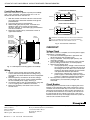
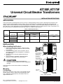
AT150F, AT175F
Universal Circuit Breaker Transformers
INSTALLATION INSTRUCTIONS
APPLICATION
These transformers provide power to 24 Vac circuits in heating/cooling control systems. Although the transformers are
typically used in heating/cooling control systems, they can be used in any application that does not exceed the load
ratings. They include a button for manually resetting the circuit breaker. They meet National Electrical Code Class 2 “not
wet” and Class 3 “wet” requirements and are Underwriters Laboratories (UL) Inc. listed under UL 1585. Transformers can
be foot-mounted or conduit/panel mounted. See Table 1 for additional specifications.
Table 1. Model Specifications.
Primary
Secondary
Voltage
At Rated Power
Output
Wiring
Connections
Output Rating
at 100 Percent
Power Factor
Model
Number
Input Voltage
(60 Hz)
Wiring
Connections
Open
Circuit
AT150F
120/208/240
9 in. leadwires
27.0
24.0
9 in. leadwires
50 VA
9 in. leadwires
27.0
24.0
9 in. leadwires
75 VA
208/277/480
AT175F
120/208/240
208/277/480
INSTALLATION
When Installing this Product…
1. Read these instructions carefully. Failure to follow
them could damage the product or cause a hazardous condition.
2. Check the ratings given in the instructions and on
the product to make sure the product is suitable for
your application.
3. Installer must be a trained, experienced service
technician.
4. After installation is complete, check out product
operation as provided in these instructions.
CAUTION
USE SCREWS OR
BOLTS THROUGH
SLOTS (4) IN
MOUNTING FEET
RESET
BUTTON
LEADWIRES
FOR PRIMARY
AND SECONDARY
CONNECTIONS
Disconnect power supply before beginning
installation to prevent electrical shock or equipment
damage.
The transformer can be foot-mounted or conduit/panel
mounted.
Mounting
MOUNTING
FOOT (2)
Foot Mounting
Mount the transformer using screws (not included) through
the four 3/16 in. x 3/8 in. holes in the mounting feet. See
Fig. 1. Make line voltage primary connections within an
approved enclosure.
® U.S. Registered Trademark
Copyright © 1996 Honeywell Inc. • All Rights Reserved
M6905
Fig. 1. Foot mounting.
X-XX UL
69-1014-1
AT150F, AT175F UNVIVERSAL CIRCUIT BREAKER TRANSFORMERS
120/208/240 VAC MODELS
Conduit/Panel Mounting
Mount the transformer on a plate or panel (not included)
with a 7/8 in. knockout. The transformer has a 1/2-14
NPSM conduit connector and lock nut.
2
COMMON
120V
PRIMARY
1. With the conduit connector side of the transformer
facing the plate, thread the leadwires through the
plate knockout.
2. Insert the connector in the knockout.
3. While holding the plate in place, assemble and
tighten the lock nut to fasten the transformer
securely. See Fig. 2. Avoid damaging the leadwires
with the screwdriver.
4. Make line voltage primary connections within an
approved enclosure.
BLACK
208V
WHITE
240V
RED
SECONDARY
1
ORANGE
208/277/480 VAC MODELS
2
COMMON
208V
PRIMARY
BLACK
277V
RED
480V
BROWN
SECONDARY
1
BLACK/RED
MOUNTING
PLATE (NOT
INCLUDED)
LEADWIRES
FOR PRIMARY
AND SECONDARY
CONNECTIONS
RESET
BUTTON
END
BELL
1
SECONDARY LEADWIRES ARE BLUE AND YELLOW LEADWIRES.
2
BLACK IS COMMON WITH RESPECT TO THE TRANSFORMER
WINDING ONLY AND NOT THE EXTERNAL CIRCUIT.
M6907
Fig. 3. Transformer schematics.
CHECKOUT
Voltage Check
After the installation is complete, turn on the power supply
and perform a voltage check.
1. Place the controlled equipment in operation and
observe through one complete cycle.
2. Using a voltmeter, verify the proper primary and
secondary voltages.
3. If the voltage readings are incorrect, make sure the
primary voltage connections are made properly.
4. Measure the voltage again.
a. If the proper primary voltage is measured and
the secondary voltage is significantly less than
the voltage shown in Table 1, the transformer
winding is damaged. Replace the transformer
and repeat the checkout procedures.
b. If the primary voltage is 0V, make sure the
power supply is connected properly or repair if
necessary. Repeat the checkout procedures.
5. Do not put the system into operation unless the
correct primary and secondary voltages are
measured.
CONDUIT
CONNECTOR
LOCK NUT
M6906
Fig. 2. Conduit/panel mounting (plate not included).
Wiring
1. All wiring must comply with local codes and ordinances. Disconnect power before making wiring
connections to prevent electrical shock or equipment
damage.
2. Make the primary connections to the line voltage
power supply. Be sure to use the correct leadwires
for the available power supply. See Fig. 3.
3. Insulate the ends of the unused leadwires using wire
nuts or capping with a solderless connector.
4. Make the secondary connections to the 24 Vac
control circuit.
Home and Building Control
Honeywell Inc.
Honeywell Plaza
P.O. Box 524
Minneapolis, MN 55408-0524
Circuit Breaker
Overloading the transformer results in tripping the circuit
breaker. If the secondary side of the transformer is short
circuited, the circuit breaker trips in less than one minute.
Reset the circuit breaker by pressing the reset button on
the side of the transformer. It can take up to one hour for
the transformer to cool, allowing it to reset. If the circuit
breaker continues to trip, thoroughly check the system for
short circuits and the current draw.
Home and Building Control
Honeywell Limited-Honeywell Limitée
155 Gordon Baker Road
North York, Ontario
M2H 2C9
69-1014—1
C.H. Rev. 9-96 Printed in China
69-1014
2
Helping You Control Your World®