1
Promira Serial Platform
The Promira Serial Platform with I2C/SPI Active - Level 1
application allows developers to interface a host PC to a
downstream embedded system environment and transfer serial
messages using the I2C and SPI protocols. Additionally, the I2C
and/or SPI pins can be used for general purpose signaling when
the respective subsystem is not in use.
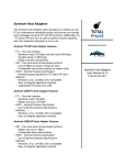
Supported products:
Promira Serial Platform Features
• I2C – Two-wire interface
◦ Standard mode (100 kHz)
◦ Fast-mode (400 kHz)
◦ Fast-mode Plus (1 MHz)
◦ Master and slave functionality
◦ Master Bit Rate 1 kHz to 1.02 MHz
◦ Slave Bit Rate 1 kHz to 500 kHz
• SPI – Four-wire serial communication protocol
◦ Master and slave functionality
◦ Master Bit Rate 31 kHz to 12.5 MHz
◦ Slave Bit Rate 31 kHz to 8 MHz
◦ Configurable slave select polarity for master mode
• GPIO – General Purpose Input/Output
◦ General purpose signaling on I2C and/or SPI pins
• Integrated Level Shifting
◦ Target Power 5V or 3.3V
◦ IO Power 0.9V - 3.45V
• Software
◦ Windows, Linux, and Mac OS X compatible
◦ Easy to integrate application interface
◦ Upgradeable Firmware over USB
Promira Serial Platform
User Manual v1.00
November 11, 2014
Promira Platform User Manual
1 General Overview
The Promira Serial Platform with I2C and SPI Active applications is a flexible,
upgradeable development platform. It can serve as a drop-in replacement for the
Aardvark I2C/SPI Host Adapter. The Promira Serial Platform hardware has been
designed to support many current and future serial interfaces. The Promira Serial
Platform with I2C and SPI Active applications connect to an analysis computer via
Ethernet or Ethernet over USB. The applications installed on the Promira Serial Platform
are field-updateable, field-upgradeable, and future-proof.
1.1 I2C Background
1.1.1 I2C History
When connecting multiple devices to a microcontroller, the address and data lines of
each devices were conventionally connected individually. This would take up precious
pins on the microcontroller, result in a lot of traces on the PCB, and require more
components to connect everything together. This made these systems expensive to
produce and susceptible to interference and noise.
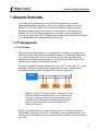
To solve this problem, Philips developed Inter-IC bus, or I2C, in the 1980s. I2C is a lowbandwidth, short distance protocol for on board communications. All devices are
connected through two wires: serial data (SDA) and serial clock (SCL).
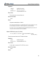
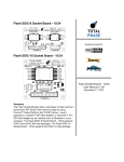
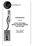
Figure 1 : Sample I2C Implementation. – Regardless of how
many slave units are attached to the I2C bus, there are only
two signals connected to all of them. Consequently, there is
additional overhead because an addressing mechanism is
required for the master device to communicate with a
specific slave device.
Because all communication takes place on only two wires, all devices must have a
unique address to identify it on the bus. Slave devices have a predefined address, but
the lower bits of the address can be assigned to allow for multiples of the same devices
on the bus.
2
Promira Platform User Manual
1.1.2 I2C Theory of Operation
I2C has a master/slave protocol. The master initiates the communication. Here is a
simplified description of the protocol. For precise details, please refer to the Philips I2C
specification. The sequence of events are as follows:
1. The master device issues a start condition. This condition informs all the slave
devices to listen on the serial data line for their respective address.
2. The master device sends the address of the target slave device and a read/write
flag.
3. The slave device with the matching address responds with an acknowledgment
signal.
4. Communication proceeds between the master and the slave on the data bus.
Both the master and slave can receive or transmit data depending on whether the
communication is a read or write. The transmitter sends 8 bits of data to the
receiver, which replies with a 1 bit acknowledgment.
5. When the communication is complete, the master issues a stop condition
indicating that everything is done.
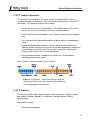
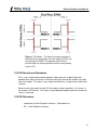
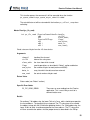
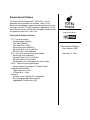
Figure 2 shows a sample bitstream of the I2C protocol.
Figure 2 : I2C Protocol. – Since there are only two wires,
this protocol includes the extra overhead of the addressing
and acknowledgement mechanisms.
1.1.3 I2C Features
I2C has many features other important features worth mentioning. It supports multiple
data speeds: standard (100 kbps), fast (400 kbps), and high speed (3.4 Mbps)
communications.
Other features include:
• Built-in collision detection,
3
Promira Platform User Manual
• 10-bit Addressing,
• Multi-master support,
• Data broadcast (general call).
For more information about other features, see the references at the end of this section.
1.1.4 I2C Benefits and Drawbacks
Since only two wires are required, I2C is well suited for boards with many devices
connected on the bus. This helps reduce the cost and complexity of the circuit as
additional devices are added to the system.
Due to the presence of only two wires, there is additional complexity in handling the
overhead of addressing and acknowledgments. This can be inefficient in simple
configurations and a direct-link interface such as SPI might be preferred.
1.1.5 I2C References
• I2C bus – NXP (Philips) Semiconductors Official I2C website
• I2C (Inter-Integrated Circuit) Bus Technical Overview and Frequently Asked
Questions – Embedded Systems Academy
• Introduction to I2C – Embedded.com
• I2C – Open Directory Project Listing
1.2 SPI Background
1.2.1 SPI History
SPI is a serial communication bus developed by Motorola. It is a full-duplex protocol
which functions on a master-slave paradigm that is ideally suited to data streaming
applications.
1.2.2 SPI Theory of Operation
SPI requires four signals: clock (SCLK), master output/slave input (MOSI), master input/
slave output (MISO), slave select (SS).
4
Promira Platform User Manual
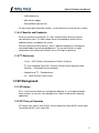
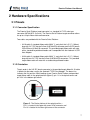
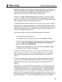
Figure 3 : Sample SPI Implementation. – Each slave device
requires a separate slave select signal (SS). This means
that as devices are added, the circuit increases in
complexity.
Three signals are shared by all devices on the SPI bus: SCLK, MOSI and MISO. SCLK
is generated by the master device and is used for synchronization. MOSI and MISO are
the data lines. The direction of transfer is indicated by their names. Data is always
transferred in both directions in SPI, but an SPI device interested in only transmitting
data can choose to ignore the receive bytes. Likewise, a device only interested in the
incoming bytes can transmit dummy bytes.
Each device has its own SS line. The master pulls low on a slaves SS line to select a
device for communication.
The exchange itself has no pre-defined protocol. This makes it ideal for data-streaming
applications. Data can be transferred at high speed, often into the range of the tens of
megahertz. The flipside is that there is no acknowledgment, no flow control, and the
master may not even be aware of the slave's presence.
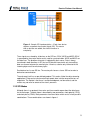
1.2.3 SPI Modes
Although there is no protocol, the master and slave need to agree about the data frame
for the exchange. The data frame is described by two parameters: clock polarity (CPOL)
and clock phase (CPHA). Both parameters have two states which results in four possible
combinations. These combinations are shown in figure 4.
5
Promira Platform User Manual
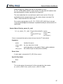
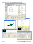
Figure 4 : SPI Modes – The frame of the data exchange is
described by two parameters, the clock polarity (CPOL) and
the clock phase (CPHA). This diagram shows the four
possible states for these parameters and the corresponding
mode in SPI.
1.2.4 SPI Benefits and Drawbacks
SPI is a very simple communication protocol. It does not have a specific high-level
protocol which means that there is almost no overhead. Data can be shifted at very high
rates in full duplex. This makes it very simple and efficient in a single-master single-slave
scenario.
Because each slave needs its own SS, the number of traces required is n+3, where n is
the number of SPI devices. This means increased board complexity when the number of
slaves is increased.
1.2.5 SPI References
• Introduction to Serial Peripheral Interface – Embedded.com
• SPI – Serial Peripheral Interface
6
Promira Platform User Manual
2 Hardware Specifications
2.1 Pinouts
2.1.1 Connector Specification
The Promira Serial Platform target connector is a standard 2x17 IDC male type
connector 0.079x0.079″ (2x2 mm). The Promira Serial Platform target connector allows
for up to a 34-pin ribbon cable and connector.
Two cables are provided with the Promira Serial Platform:
• 34-10 cable: A standard ribbon cable 0.039″ (1 mm) pitch that is 5.12″ (130mm)
long with 2x17 IDC female 2x2mm (0.079x0.079) connector and 2x5 IDC female
2.54x2.54mm (0.10x0.10) connector. This provided target ribbon cable will mate
with a standard keyed boxed header and is compatible with the Aardvark I2C/SPI
Host Adapter.
• 34-34 cable: A standard ribbon cable 0.039″ (1 mm) pitch that is 5.12″ (130mm)
long with two 2x17 IDC female 2x2mm (0.079x0.079) connectors. This provided
target ribbon cable will mate with a standard keyed boxed header.
2.1.2 Orientation
The pin order in the 2x5 IDC female connector in the provided target ribbon 34-10 cable
is identical to the order used by the Aardvark I2C/SPI Host Adapter. The brown line
indicates the first position. When looking at your Promira Serial Platform and provided
target ribbon cable in the upright position (figure 5), pin 1 is in the top left corner and
pin 10 is in the bottom right corner.
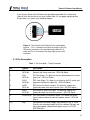
Figure 5 : The Prmira platform in the upright position. –
Pin 1 is located in the upper left corner of the connector and
Pin 10 is located in the lower right corner of the connector.
7
Promira Platform User Manual
If you flip your Promira Serial Platform and provided target ribbon 34-10 cable over
(figure 6) such that the text on the serial number label is in the proper upright position,
the pin order is as shown in the following diagram.
Figure 6 : The Promira Serial Platform in the upside down
position. – Pin 1 is located in the lower left corner of the 2x5
IDC female connector in the provided target ribbon 34-10
cable and Pin 10 is located in the upper right corner of this
connector.
2.1.3 Pin Description
Table 1 : Pin Description - Target Connector
Pin
Symbol
Description
1
SCL/
GPIO-00
I2C Clock Signal. This clock line synchronizes communication
between the master and slave. / GPIO-00 Signal.
3
SDA/
GPIO-01
I2C Data Signal. This data line transfers data between the master
and slave. / GPIO-01 Signal.
7
SCLK/
GPIO-03
SPI Clock Signal. This clock line is driven by the SPI master and
regulates the flow of the data bits. / GPIO-03 Signal.
8
MOSI/
GPIO-04
SPI Master Out Slave In Signal. This data line supplies the
output data from the master into the slave. / GPIO-04 Signal.
5
MISO/
GPIO-02
SPI Master In Slave Out Signal. This data line supplies the
output data from the slave to the master. / GPIO-02 Signal.
9
SS/GPIO-05
SPI Slave Select (Chip Select) Signal. This control line allows
slaves to be turned on and off via hardware control. / GPIO-05
Signal.
4, 6
Vtgt
Configurable Vcc Power Supply. No Connect/3.3 V/5 V. These
Vcc pins are switched through the API or software GUI tool, and
are used to power a downstream target, such as an I2C/SPI
EEPROM/flash.
8
Promira Platform User Manual
22, 24
IOVcc
Configurable Vcc IO level Power Supply. No Connect/0.9 V to
3.45 V. These Vcc IO pins are switched through the API or
software GUI tool, and are used to power a downstream target,
such as an I2C/SPI EEPROM/flash.
2, 10, 12, 16,
18, 28, 32, 34
GND
Ground Connection. If the ground of the target system and the
Promira Serial Platform are not connected together, then the
signaling is entirely unpredictable and communication will likely
be corrupted.
11, 13, 14, 15,
17, 19, 21, 23,
25, 26, 27, 29,
31, 33
Reserved
2.2 I2C Signaling Characteristics
2.2.1 Speed
The Promira Serial Platform I2C master can operate at a maximum bitrate of 1.02 MHz
and supports many intermediate bitrates between 1 kHz and 1.02 MHz. The power-on
default bitrate for the I2C master unit is 100 kHz.
For slave functionality, the Promira Serial Platform can operate at any rate between 1
kHz and 500 kHz.
It is not possible to send bytes at a throughput of exactly 1/8 times the bitrate. The I2C
protocol requires that 9 bits are sent for every 8 bits of data. In addition, even though
there is no inter-byte delay for the most part of the I2C transaction, the Promira Serial
Platform occasionally requires additional time to process the received bytes and set up
the next portion of the transaction. In this case, delay is inserted on the I2C bus.
There can be extra overhead introduced by the operating system between calls to the
Promira API. These delays will further reduce the overall throughput across multiple
transactions. To achieve the fastest throughput, it is advisable to send as many bytes as
possible in a single transaction (i.e., a single call to the Promira API).
2.2.2 Pull-up Resistors
There is a pull up resistor on each I2C line (SCL, SDA). The lines are effectively pulled
up to 0.9V-3.45V. The pull up resistor is 2.2K OHM for 2.2V - 3.45V I2C signal level. The
pull up resistor is 520 OHM for 1.2V - 2.2V I2C signal level. The pull up resistor is 422
OHM for 0.9V - 1.2V I2C signal level. If the Promira Serial Platform is connected to an I2
C bus that also includes pull-up resistors, the total pull-up current could be potentially
larger. The I2C specification allows for a maximum of 3 mA pull-up current on each I2C
line.
9
Promira Platform User Manual
A good rule of thumb is that if a downstream I2C device can sink more than 5 mA of
current, the protocol should operate properly. Stronger pull-up resistors and larger sink
currents may be required for fast bitrates, especially if there is a large amount of
capacitance on the bus. The Promira Serial Platform is able to sink approximately 10 mA
per pin, so it is possible to have two Promira Serial Platforms communicate with each
other as master and slave, with both devices pull-up resistors enabled.
Promira Serial Platform pull-up resistors can be switched and configured through the
software GUI and API. Refer to the API section for more details.
2.2.3 I2C Clock Stretching
When the Promira Serial Platform is configured as an I2C master, it supports both interbit and inter-byte slave clock-stretching. If a slave device pulls SCL low during a
transaction, the adapter will wait until SCL has been released before continuing with the
transaction.
2.2.4 Known I2C Limitations
The Promira Serial Platform I2C master occasionally requires additional time to process
the received bytes and set up the next bytes. In this case, delay is inserted on the I2C
bus. Every Promira Serial Platform I2C master read transaction will have a delay before
the last byte, and there may be additional delays between bytes during I2C master read
and write.
The Promira Serial Platform can keep the slave functions enabled even while master
operations are executed through the same adapter.
Multi-master is also supported: If there is a bus collision during data transmission and
the Promira Serial Platform loses the bus, the transaction will be cut short and the host
API will report that fewer bytes were transmitted than the requested number. This
condition can be distinguished from the case in which the downstream slave cuts short
the transmission by sending a NACK by using the function ps_i2c_read.
This constraint can be phrased in a different manner. Say that I2C master device A has a
packet length of X bytes. If there is a second I2C master device B, that sends packets of
length greater than X bytes, the first X bytes should never contain exactly the same data
as the data sent by device A. Otherwise the results of the arbitration will be undefined.
This is a constraint found with most I2C master devices used in a multi-master
environment.
10
Promira Platform User Manual
2.3 SPI Signaling Characteristics
2.3.1 Speeds
The Prmira Platform SPI master can operate at bitrates between 31 kHz and 12.5 MHz.
The power-on default bitrate is 992 kHz. The quoted bitrates are only achievable within
each individual byte and does not extend across bytes. Even though there is no interbyte delay for the most part of the SPI transaction, the Promira Serial Platform SPI
master occasionally requires additional time to process the received bytes and set up the
next bytes. In this case, a delay is inserted on the SPI bus. Every Promira Serial
Platform SPI master transaction will have a delay of one half clock between the first byte
and the second byte, and there may be additional delays between bytes on 128 byte
boundaries.
The Promira Serial Platform SPI slave can operate at any bitrate from 31 KHz up to 8
MHz.
When the Promira Serial Platform is configured to act as an SPI slave, and the slave
select is pulled high to indicate the end of a transaction, there is a data processing
overhead of sending the transaction to the PC host. As such, if the SPI master sends a
subsequent transaction in rapid succession to the Promira Platform slave, the data
received by the Promira Serial Platform slave may be corrupted. There is no precise
value for this minimum inter-transaction time, but a suggested spacing is approximately
100-200 µs.
See also section 2.3.3
2.3.2 Pin Driving
When the SPI interface is activated as a master, the slave select line (SS) is actively
driven low. The MOSI and SCK lines are driven as appropriate for the SPI mode. After
each transmission is complete, these lines are returned to a high impedance state. This
feature allows the Promira Serial Platform, following a transaction as a master SPI
device, to be then reconnected to another SPI environment as a slave. The Promira
Platform will not fight the master lines in the new environment.
It is advisable that every slave also have passive pull-ups on the MOSI and SCK lines.
These pull-up resistors can be relatively weak – 100k should be adequate.
As a slave, the MOSI, SCK, and SS lines are configured as an input and the MISO line is
configured as an output. This configuration is held as long as the slave mode is enabled
(see the API documentation later in the manual).
11
Promira Platform User Manual
2.3.3 Known SPI Limitations
The Promira Serial Platform SPI master occasionally requires additional time to process
the received bytes and set up the next bytes. In this case, a delay is inserted on the SPI
bus. Every Promira Serial Platform SPI master transaction will have a delay of half clock
between the first byte and the second byte, and there may be additional delays between
bytes on 128 byte boundaries of 600 µs max. Over a large transfer, the average delay
period is very low.
It is only possible to reliably send and receive transactions of 4 KiB or less as an SPI
master or slave. This is due to operating system issues and the full-duplex nature of the
SPI signaling.
2.4 USB 2.0 Compliance
The Promira Serial Platform is USB 2.0 compliant and will operate as a high speed
(480 Mbps) device on a USB 2.0 hub or host controller. For additional information see
table 15.
2.5 Physical Specifications
• Dimensions: W x D x L: 77.5 mm x 29.2 mm x 115.6 mm (3.05" x 1.15" x 4.55")
• Weight: 153 g (0.34 lbs)
12
Promira Platform User Manual
3 Software
3.1 Compatibility
3.1.1 Overview
The Promira Serial Platform software is offered as a 32-bit or 64-bit Dynamic Linked
Library (or shared object). The specific compatibility for each operating system is
discussed below.
3.1.2 Windows Compatibility
The Promira Serial Platform software is compatible with 32-bit and 64-bit versions of
Windows 7, and Windows 8/8.1.
Windows XP, Vista, 2000 and legacy 16-bit Windows 95/98/ME operating systems are
not supported.
3.1.3 Linux Compatibility
The Promira Serial Platform software is compatible with all standard 32-bit and 64-bit
distributions of Linux with kernel 2.6 and integrated USB support. When using the 32-bit
library on a 64-bit distribution, the appropriate 32-bit system libraries are also required.
3.1.4 Mac OS X Compatibility
The Promira Serial Platform software is compatible with Intel versions of Mac OS X
10.5 Leopard, 10.6 Snow Leopard, 10.7 Lion, 10.8 Mountain Lion, and 10.9 Mavericks.
Installation of the latest available update is recommended.
3.2 Connectivity
There are two ways to connect to the Promira Serial Platform: via USB or via Ethernet.
No additional device drivers are required for using either method.
3.2.1 USB
The Promira Serial Platform uses Ethernet over USB, which allows the host software to
connect to the adapter via an IP address. To use this interface, connect the device to
your PC with a USB cable and follow the instructions below to set up the connection on
the PC.
13
Promira Platform User Manual
For Ethernet over USB, the Promira Serial Platform is a DHCP server that dynamically
distributes network configuration parameters, such as IP addresses for interfaces and
services.
Windows
1. Connect Promira to PC with USB cable.
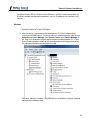
2. After the device is connected to the development PC, OS will automatically
search for the RNDIS driver. To verify the drive is installed correctly, right click on
Computer and select Manage. From System Tools, select Device Manager. It
will show a list of devices currently connected with the development PC. If Total
Phase Promira platform shows up with an exclamation mark implying that driver
has not been installed, continue to the next step.
Otherwise, close this windows, skip RNDIS driver installation in the next step and
continue to the following step.
14
Promira Platform User Manual
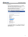
3. Install RNDIS driver:
◦ Right click on Total Phase Promira platform device and select Update
Driver Software... When prompted to choose how to search for device driver
software, choose Browse my computer for driver software.
◦ Browse for driver software on your computer will come up. Select Let me
pick from a list of device drivers on my computer.
◦ A window will come up asking to select the device type. Select Network
adapters, as RNDIS emulates a network connection.
◦ In the Select Network Adapter window, select Microsoft Corporation from
the Manufacturer list. Under the list of Network Adapter:, select Remote
NDIS compatible device.
15
Promira Platform User Manual
◦ The Total Phase Promira platform device is now installed and ready for use.
4. From the Start menu, select Control Panel | Network and Internet | Network
and Sharing Center.
5. Select Change adapter settings on the left panel.
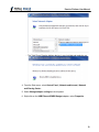
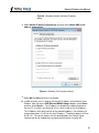
6. Right click on the USB Ethernet/RNDIS Gadget adapter, select Properties.
16
Promira Platform User Manual
Figure 7 : Windows Change adapter settings
window.
7. Double click on Internet Protocol Version 4 (IPv4).
17
Promira Platform User Manual
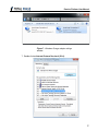
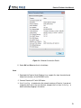
Figure 8 : Windows Network Interface Properties
dialog.
8. Select Obtain IP address automatically and also select Obtain DNS server
address automatically.
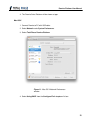
Figure 9 : Windows IPv4 Properties dialog.
9. Select OK and Close to dismiss the dialogs.
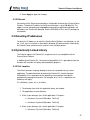
10. In order to make sure it is ready or to know the IP address of the Promira Serial
Platform, right click on the USB Ethernet/RNDIS Gadget adapter, select Status
and then select Details.... The IP address assigned to the network interface on
the host PC is will be in the format of 10.x.x.x and is listed as the IPv4 Address.
The IP address of the device will be at the preceding address. For example, the
image below shows 10.1.0.2 for the host IP address. The device address will then
be 10.1.0.1. This device address will also be displayed in the Control Center
software and will be needed when connecting to the device using the API.
18
Promira Platform User Manual
Figure 10 : Windows Connection Details.
11. Select OK and Close to dismiss the dialogs.
Linux
1. Download the Promira Serial Platform Linux support files from the website and
follow the instructions in the README.txt file.
2. Connect Promira to PC with USB cable.
3. Use ifconfig -a to determine the network interface of Promira. If you do not
recognize which one is the new interface, compare the lists from ifconfig -a
before and after plugging in the device.
19
Promira Platform User Manual
4. The Promira Serial Platform will be shown as tppx.
Mac OS X
1. Connect Promira to PC with USB cable.
2. Select Network under System Preferences.
3. Select Total Phase Promira Platform.
Figure 11 : Mac OS X Network Preferences
window.
4. Select Using DHCP from the Configure IPv4: dropdown list box.
20
Promira Platform User Manual
5. Select Apply to apply the changes.
3.2.2 Ethernet
Connecting via the Ethernet port provides a configurable interface to the Promira Serial
Platform. The default IP address of the Ethernet interface is set to 192.168.11.1. This
address can be changed using the promira command-line application provided in the
util folder in the Promira API package. See the README.txt file in the API package for
more details.
3.3 Detecting IP addresses
To detect the IP addresses to which the Promira Serial Platforms are attached, use the
pm_find_devices routine as described in following API documentation. Alternatively,
the Control Center software can be used to list the available devices.
3.4 Dynamically Linked Library
The Promira requires the Promira DLL to operate and is only compatible with the
Promira Serial Platform.
In addition to the Promira DLL, the Aardvark Compatibility DLL is provided to make the
Aardvark API available for legacy and compatibility purposes.
3.4.2 DLL Location
Total Phase provides language bindings that can be integrated into any custom
application. The default behavior of locating the Promira DLL and the Aardvark
Compatibility DLL is dependent on the operating system platform and specific
programming language environment. For example, for a C or C++ application, the
following rules apply:
On a Windows system, this is as follows:
1. The directory from which the application binary was loaded.
2. The applications current directory.
3. 32-bit system directory (for a 32-bit application). Examples:
◦ c:\Windows\System32 [Windows 7/8 32-bit]
◦ c:\Windows\SysWow64 [Windows 7/8 64-bit]
4. 64-bit system directory (for a 64-bit application). Examples:
◦ C:\Windows\System32 [Windows 7/8 64-bit]
21
Promira Platform User Manual
5. The Windows directory. (Ex: c:\Windows )
6. The directories listed in the PATH environment variable.
On a Linux system, this is as follows:
1. First, search for the shared object in the application binary path. If the /proc
filesystem is not present, this step is skipped.
2. Next, search in the applications current working directory.
3. Search the paths explicitly specified in LD_LIBRARY_PATH.
4. Finally, check any system library paths as specified in /etc/ld.so.conf and
cached in /etc/ld.so.cache.
On a Mac OS X system, this is as follows:
1. First, search for the shared object in the application binary path.
2. Next, search in the applications current working directory.
3. Search the paths explicitly specified in DYLD_LIBRARY_PATH.
4. Finally, check the /usr/lib and /usr/local/lib system library paths.
If the DLL is still not found, an error will be returned by the binding function. The error
code is PM_UNABLE_TO_LOAD_LIBRARY for the management API and
PS_APP_UNABLE_TO_LOAD_LIBRARY for the application API.
3.4.3 DLL Versioning
The Aardvark Compatibility DLL checks to ensure that the firmware of a given device is
compatible. Each DLL revision is tagged as being compatible with firmware revisions
greater than or equal to a certain version number. Likewise, each firmware version is
tagged as being compatible with DLL revisions greater than or equal to a specific version
number.
Here is an example.
DLL v1.20: compatible with Firmware >= v1.15
Firmware v1.30: compatible with DLL >= v1.20
Hence, the DLL is not compatible with any firmware less than version 1.15 and the
firmware is not compatible with any DLL less than version 1.20. In this example, the
version number constraints are satisfied and the DLL can safely connect to the target
22
Promira Platform User Manual
firmware without error. If there is a version mismatch, the API calls to open the device
will fail. See the API documentation for further details.
3.5 Rosetta Language Bindings: API Integration into
Custom Applications
3.5.1 Overview
The Promira Rosetta language bindings make integration of the Promira API into custom
applications simple. Accessing Promira functionality simply requires function calls to the
Promira API. This API is easy to understand, much like the ANSI C library functions,
(e.g., there is no unnecessary entanglement with the Windows messaging subsystem
like development kits for some other embedded tools).
First, choose the Rosetta bindings appropriate for the programming language. Different
Rosetta bindings are included in the software download package available on the Total
Phase website. Currently the following languages are supported: C/C++, Python. Next,
follow the instructions for each language binding on how to integrate the bindings with
your application build setup. As an example, the integration for the C language bindings
is described below. (For information on how to integrate the bindings for other
languages, please see the example code available for download on the Total Phase
website.)
1. Include the promira.h and promact_is.h files in any C or C++ source
module. The module may now use any API call listed in promira.h and
promact_is.h.
2. Compile and link promira.c and promact_is.c with your application. Ensure
that the include path for compilation also lists the directory in which promira.h
and promact_is.h is located if the two files are not placed in the same
directory.
3. Place the Promira DLL (promira.dll), included with the API software package, in
the same directory as the application executable or in another directory such that
it will be found by the previously described search rules.
3.5.2 Aardvark Compatibility
The Aardvark Compatibility Rosetta language bindings make it simple to integrate the
Aardvark API into a custom application using the Promira Serial Platform. Similar to the
Promira language bindings above, follow the instructions for each language binding on
23
Promira Platform User Manual
how to integrate the bindings with your application build setup. As an example, the
integration for the C language bindings is described below.
1. Include the aa_pm.h file included with the API software package in any C or C++
source module. The module may now use any Aardvark API call listed in
aa_pm.h.
2. Compile and link aa_pm.c with your application. Ensure that the include path for
compilation also lists the directory in which aa_pm.h is located if the two files are
not placed in the same directory.
3. Place the Promira DLL (promira.dll) and the Aardvark Compatibility DLL
(aa_pm.dll), included with the API software package, in the same directory as the
application executable or in another directory such that it will be found by the
previously described search rules.
3.5.3 Versioning
Since a new Promira DLL and Aardvark Compatibility DLL can be made available to an
already compiled application, it is essential to ensure the compatibility of the Rosetta
binding used by the application (e.g., aa_pm.c ) against the DLL loaded by the system.
A system similar to the one employed for the DLL-Firmware cross-validation is used for
the binding and DLL compatibility check.
Here is an example.
DLL v1.20: compatible with Binding >= v1.10
Binding v1.15: compatible with DLL >= v1.15
The above situation will pass the appropriate version checks. The compatibility check is
performed within the binding. If there is a version mismatch, the API function will return
an error code, PS_APP_INCOMPATIBLE_LIBRARY.
3.5.4 Customizations
While provided language bindings stubs are fully functional, it is possible to modify the
code found within this file according to specific requirements imposed by the application
designer.
For example, in the C bindings one can modify the DLL search and loading behavior to
conform to a specific paradigm. See the comments in promira.c or aa_pm.c for more
details.
24
Promira Platform User Manual
4 Firmware
4.1 Field Upgrades
4.1.1 Upgrade Philosophy
The Promira Serial Platform is designed so that its internal firmware can be upgraded by
the user, thereby allowing the inclusion of any performance enhancements or critical
fixes available after the receipt of the device.
4.1.2 Upgrade Procedure
Please refer to the Control Center software user manual for the procedure to upgrade
the firmware on the Promira Serial Platform.
25
Promira Platform User Manual
5 API Documentation
5.1 Introduction
The Promira API documentation that follows is oriented toward the Promira Rosetta C
bindings. The set of Promira API functions and their functionality is identical regardless
of which Rosetta language binding is utilized. The only differences will be found in the
calling convention of the functions. For further information on such differences please
refer to the documentation that accompanies each language bindings in the Promira API
Software distribution.
5.2 General Data Types
The following definitions are provided for convenience. All Promira data types are
unsigned.
typedef
typedef
typedef
typedef
typedef
typedef
typedef
typedef
typedef
unsigned
unsigned
unsigned
unsigned
signed
signed
signed
signed
float
char
short
int
long long
char
short
int
long long
u08;
u16;
u32;
u64;
s08;
s16;
s32;
s64;
f32;
5.3 Notes on Status Codes
Most of the Promira API functions can return a status or error code back to the caller.
The complete list of status codes is provided at the end of this chapter. All of the error
codes are assigned values less than 0, separating these responses from any numerical
values returned by certain API functions.
Each API function can return one of two error codes with regard to the loading of the
underlying Promira DLL, PS_APP_UNABLE_TO_LOAD_LIBRARY and
PS_APP_INCOMPATIBLE_LIBRARY. If these status codes are received, refer to the
previous sections in this manual that discuss the DLL and API integration of the Promira
software. Furthermore, all API calls can potentially return the error
PS_APP_UNABLE_TO_LOAD_FUNCTION. If this error is encountered, there is likely a
serious version incompatibility that was not caught by the automatic version checking
system. Where appropriate, compare the language binding versions (e.g.,
PM_HEADER_VERSION found in promira.h and PM_CFILE_VERSION found in
promira.c or PS_APP_HEADER_VERSION found in promact_is.h and
26
Promira Platform User Manual
PS_APP_CFILE_VERSION found in promact_is.c) to verify that there are no
mismatches. Next, ensure that the Rosetta language binding (e.g., promira.c and
promira.h or promact_is.c and promact_is.h) are from the same release as the
Promira DLL. If all of these versions are synchronized and there are still problems,
please contact Total Phase support for assistance.
Any API function that accepts any type of handle can return the error
PS_APP_INVALID_HANDLE if the handle does not correspond to a valid instance that
has already been opened or created. If this error is received, check the application code
to ensure that the open or create command returned a valid handle and that this handle
is not corrupted before being passed to the offending API function.
Finally, any function call that communicates with an Promira device can return the error
PS_APP_COMMUNICATION_ERROR. This means that while the handle is valid and the
communication channel is open, there was an error receiving the acknowledgment
response from the Promira application. This can occur in situations where the incoming
data stream has been saturated by asynchronously received messages an outgoing
message is sent to the Promira application, but the incoming acknowledgment is
dropped by the operating system as a result of the incoming USB receive buffer being
full. The error signifies that it was not possible to guarantee that the connected Promira
device has processed the host PC request, though it is likely that the requested action
has been communicated to the Promira device and the response was simply lost. For
example, if the slave functions are enabled and the incoming communication buffer is
saturated, an API call to disable the slave may return
PS_APP_COMMUNICATION_ERROR even though the slave has actually been disabled.
If either the I2C or SPI subsystems have been disabled by ps_app_configure, all
other API functions that interact with I2C or SPI will return PS_I2C_NOT_ENABLED or
PS_SPI_NOT_ENABLED, respectively.
These common status responses are not reiterated for each function. Only the error
codes that are specific to each API function are described below.
All of the possible error codes, along with their values and status strings, are listed
following the API documentation.
5.4 Application Management Interface
5.4.1 Application Management
Find Devices (pm_find_devices)
int pm_find_devices (int
num_devices,
u32 * devices);
Get a list of IP addresses to which Promira adapters are attached.
27
Promira Platform User Manual
Arguments
num_devices
maximum size of the array
devices
array into which the IP addresses are returned
Return Value
This function returns the number of devices found, regardless of the array size.
Specific Error Codes
None.
Details
Each element of the array is 4 byte integer value represented IP address. For
instance, "192.168.1.2" is 0x0201A8C0.
Two IP addresses to same device might be returned when both Ethernet and
Ethernet over USB are enabled.
If the input array is NULL, it is not filled with any values.
If there are more devices than the array size (as specified by num_devices), only
the first num_devices IP addresses will be written into the array.
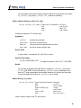
Find Devices (pm_find_devices_ext)
int pm_find_devices_ext (int
num_devices,
u16 * devices,
int
num_ids,
u32 * unique_ids
int
num_statuses
u32 * statues);
Get a list of IP addresses and unique IDs to which Promira Serial Platforms are
attached.
Arguments
num_devices
maximum number of IP addresses to return
devices
array into which the IP addresses are returned
num_ids
maximum number of unique IDs to return
unique_ids
array into which the unique IDs are returned
num_statuses
maximum number of statuses to return
28
Promira Platform User Manual
statuses
array into which the statuses are returned
Return Value
This function returns the number of devices found, regardless of the array sizes.
Specific Error Codes
None.
Details
This function is the same as pm_find_devices() except that is also returns the
unique IDs of each Promira adapter. The IDs are guaranteed to be non-zero if valid.
The IDs are the unsigned integer representation of the 10-digit serial numbers.
The number of devices and IDs returned in each of their respective arrays is
determined by the minimum of num_devices, num_ids, and statuses.
If status is PM_DEVICE_NOT_FREE, the device is in-use by another host and is
not ready for connection.
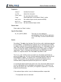
Open a Promira Serial Platform (pm_open)
Promira pm_open (const char * net_addr);
Open a connection to a Promira Serial Platform.
Arguments
net_addr
net address of the Promira Serial Platform. It could be an
IPv4 address or a host name.
Return Value
This function returns a Promira handle, which is guaranteed to be greater than zero
if valid.
Specific Error Codes
PM_UNABLE_TO_OPEN
The specified net address is not
connected to a Promira Serial Platform.
PM_INCOMPATIBLE_DEVICE
There is a version mismatch between the
DLL and the firmware. The DLL is not of a
sufficient version for interoperability with
the firmware version or vice versa.
29
Promira Platform User Manual
Details
None.
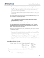
Close the Promira device (pm_close)
int pm_close (Promira promira);
Close the connection to the Promira adapter.
Arguments
promira
handle of the connection to the Promira Serial Platform to be closed
Return Value
The number of devices closed is returned on success. This will usually be 1.
Specific Error Codes
None.
Details
If the promira argument is zero, the function will attempt to close all possible
handles, thereby closing all connections to Promira Serial Platforms. The total
number of connections to Promira Serial Platforms closed is returned by the
function.
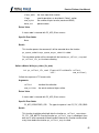
Launch an application (pm_load)
int pm_load (Promira
promira,
const char * app_name);
Launch an application.
Arguments
promira
handle of the connection to the Promira Serial Platform
app_name
application name to be launched
Return Value
A Promira status code is returned with PM_OK on success.
Specific Error Codes
30
Promira Platform User Manual
PM_APP_NOT_FOUND
There is no application with the specified name.
PM_UNABLE_TO_LOAD_APP
Unable to load the application.
Details
The Promira Serial Platform can have more than one application. Prior to the use of
any subsystems in the application, it need to be launched.
The Promira Serial Platform with firmware version 0.65 or greater has one
application and its name is "com.totalphase.promact_is".
Get IP address (pm_query_net)
int pm_query_net (Promira
int
u08 *
int
u08 *
promira,
ip_addr_len,
ip_addr,
netmask_len,
netmask);
Get IP address and network mask for this Promira handle.
Arguments
promira
handle of the connection to the Promira Serial Platform
ip_addr_len
size of the array for IP address
ip_addr
array into which the IP address is returned
netmask_len
size of the array for network mask
netmask
array into which the network mask is returned
Return Value
A Promira status code is returned with PM_OK on success.
Specific Error Codes
None.
Details
None.
Configure IP address (pm_config_net)
int pm_config_net (Promira
promira,
const char * ip_addr,
31
Promira Platform User Manual
const char * netmask);
Configure the Ethernet network interface.
Arguments
promira
handle of the connection to the Promira Serial Platform
ip_addr
IP address string.
netmask
network mask string.
Return Value
A Promira status code is returned with PM_OK on success.
Specific Error Codes
PM_NETCONFIG_ERROR
Unable to configure network interface.
PM_INVALID_IPADDR
Invalid IP address.
PM_INVALID_NETMASK
Invalid network mask.
PM_INVALID_SUBNET
The 192.168.12.x subnet is reserved. It is
an error to configure the Ethernet interface to
any address in this subnet.
Details
Network interface can be configured by the promira utility (promira.exe or
promira). See the section Ethernet for more detail.
5.5 General Application Interface
5.5.1 General Application
Connect to the Application (ps_app_connect)
PromiraConnectionHandle ps_app_connect (const char * net_addr)
Connect to the application launched by pm_load().
Arguments
net_addr
The net address of the Promira Serial Platform. It could be
an IPv4 address or a host name.
Return Value
32
Promira Platform User Manual
This function returns a connection handle, which is guaranteed to be greater than
zero if valid.
Specific Error Codes
PS_APP_UNABLE_TO_OPEN
Unable to connect to the
application.
PS_APP_UNABLE_TO_INIT_SUBSYSTEM
Failed to initialize one of
subsystems (I2C, SPI, or
GPIO) in the Promira
application.
Details
More than one connection can be made to the application. Also note that the
application can be shared by many user applications.
Disconnect to the Application (ps_app_disconnect)
int ps_app_disconnect (PromiraConnectionHandle conn)
Disconnect to the application.
Arguments
conn
handle of the connection to the application
Return Value
The number of the connections to applications disconnected is returned on success.
This will usually be 1.
Specific Error Codes
None.
Details
If the conn argument is zero, the function will attempt to disconnect all possible
handles, thereby disconnecting all connected handles. The total number of handle
disconnected is returned by the function.
Version (ps_app_version)
int ps_app_version (PromiraChannelHandle channel,
PromiraAppVersion * version);
33
Promira Platform User Manual
Return the version matrix for the application connected to the given handle.
Arguments
channel
handle of the channel
version
pointer to pre-allocated structure
Return Value
A status code is returned with PS_APP_OK on success.
Specific Error Codes
None.
Details
The PromiraAppVersion structure describes the various version dependencies of
application components. It can be used to determine which component caused an
incompatibility error.
struct PromiraAppVersion {
/* Software, firmware, and hardware versions. */
u16 software;
u16 firmware;
u16 hardware;
/* FW requires that SW must be >= this version. */
u16 sw_req_by_fw;
/* SW requires that FW must be >= this version. */
u16 fw_req_by_sw;
/* API requires that SW must be >= this version. */
u16 api_req_by_sw;
};
If the handle is 0 or invalid, only software, fw_req_by_sw, and api_req_by_sw
version are set.
Sleep (ps_app_sleep_ms)
int ps_app_sleep_ms (u32 milliseconds);
Sleep for given amount of time.
34
Promira Platform User Manual
Arguments
milliseconds
number of milliseconds to sleep
Return Value
This function returns the number of milliseconds slept.
Specific Error Codes
None.
Details
This function provides a convenient cross-platform function to sleep the current
thread using standard operating system functions.
The accuracy of this function depends on the operating system scheduler. This
function will return the number of milliseconds that were actually slept.
Status String (ps_app_status_string)
const char *ps_app_status_string (int status);
Return the status string for the given status code.
Arguments
status
status code returned by a Promira application function.
Return Value
This function returns a human readable string that corresponds to status. If the code
is not valid, it returns a NULL string.
Specific Error Codes
None.
Details
35
Promira Platform User Manual
None.
5.5.2 Channel
Open a Channel (ps_channel_open)
PromiraChannelHandle ps_channel_open (PromiraConnectionHandle conn);
Open a logical communication channel.
Arguments
conn
handle of the connection to the application
Return Value
This function returns a channel handle, which is guaranteed to be greater than zero
if valid.
Specific Error Codes
None.
Details
Channel is a logical communication layer that talks to the application. All commands
to the launched application will be executed through the specified channel.
Close the Channel (ps_channel_close)
int ps_channel_close (PromiraChannelHandle channel);
Close the logical communication channel with the specified handle.
Arguments
channel
handle of the channel
Return Value
A status code is returned with PS_APP_OK on success.
Specific Error Codes
None.
Details
36
Promira Platform User Manual
None.
5.5.3 Queue
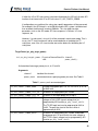
Create a Queue (ps_queue_create)
PromiraQueueHandle ps_queue_create (
PromiraConnectionHandle conn,
u08
queue_type);
Create a batch queue.
Arguments
conn
handle of the connection to the application
queue_type
type of queue. See Table 2
Table 2 : queue_type enumerated types
PS_MODULE_ID_I2C_ACTIVE An I2C queue.
PS_MODULE_ID_SPI_ACTIVE A SPI queue.
Return Value
This function returns a queue handle, which is guaranteed to be greater than zero if
valid.
Specific Error Codes
None.
Details
In order to use the Promira Serial Platform to send data across the bus at high
speed, data and commands can be accumulated in a queue until a call is made to
batch shift all of the queued data and commands.
The queue can contain only data or command to be sent over same type of the bus.
For instance, any SPI data or command cannot be queued to an I2C queue.
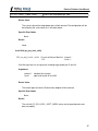
Destroy the Queue (ps_queue_destroy)
int ps_queue_destroy (PromiraQueueHandle queue);
37
Promira Platform User Manual
Destroy the queue.
Arguments
queue
handle of the queue
Return Value
A status code is returned with PS_APP_OK on success.
Specific Error Codes
None.
Details
None.
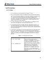
Clear the Queue (ps_queue_clear)
int ps_queue_clear (PromiraQueueHandle queue);
Clear the batch queue.
Arguments
queue
handle of the queue
Return Value
A status code is returned with PS_APP_OK on success.
Specific Error Codes
None.
Details
All queued data and commands are removed from the queue.
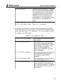
Queue a Delay in Milliseconds (ps_queue_delay_ms)
int ps_queue_delay_ms (PromiraQueueHandle queue,
int
milliseconds);
Queue a delay value on the bus in units of milliseconds.
Arguments
38
Promira Platform User Manual
queue
handle of the queue
milliseconds
amount of time for delay in milliseconds
Return Value
A status code is returned with PS_APP_OK on success.
Specific Error Codes
None.
Details
Queues milliseconds amount of delay on the bus.
Queue a Sync Command (ps_queue_sync)
int ps_queue_sync (PromiraQueueHandle queue);
Queue a sync command that waits all commands to be executed
Arguments
queue
handle of the queue
Return Value
A status code is returned with PS_APP_OK on success.
Specific Error Codes
None.
Details
The commands in queues to a single subsystem (I2C, SPI, or GPIO) will be
executed in order that command comes into the subsystem. However The
commands in queues to multiple subsystems will be executed parallelly and cannot
be guaranteed which one will be done first. This function is to wait all commands to
be executed from all subsystems.
Get a number of commands (ps_queue_size)
int ps_queue_size (PromiraQueueHandle queue);
Get a number of commands in a queue.
39
Promira Platform User Manual
Arguments
queue
handle of the queue
Return Value
The number of command is the queue will be returned.
Specific Error Codes
None.
Details
None.
Submit the Batch Shift (ps_queue_submit)
PromiraCollectHandle ps_queue_submit (
PromiraQueueHandle
PromiraChannelHandle
u08
u08 *
queue,
channel,
ctrlId,
queue_type);
Perform the current batch queue.
Arguments
queue
handle of the queue
channel
handle of the channel
ctrlId
index of the subsystem
queue_type
type of queue
Return Value
This function returns a collect handle, which is guaranteed to be greater than zero if
valid.
Specific Error Codes
None.
Details
This function performs all of the accumulated commands in the queue and shifts
them in order to the subsystem (I2C or SPI). After the operation completes, the
batch queue is not cleared. Therefore, this function may be called repeatedly if the
same sequence of commands is to be shifted across the bus multiple times.
40
Promira Platform User Manual
When there are any batches uncollected, this function will return
PS_APP_PENDING_ASYNC_CMD.
The queue_type tells what type of queue commands are executed.
This function is a block function and will be returned when first command of the
queue is executed and host receives the response of first command with a collect
handle. In order to receive the responses for the remained commands in queue, use
the function ps_collect_resp.
If ps_queue_submit is called before all responses are collected, all uncollected
responses of the previous queue will be discarded.
Submit an Asynchronous Shift (ps_queue_async_submit)
int ps_queue_async_submit (PromiraQueueHandle
queue,
PromiraChannelHandle channel,
u08
ctrlId);
Submit the shift operations in the queue for asynchronous execution.
Arguments
queue
handle of the queue
channel
handle of the channel
ctrlId
index of the subsystem
Return Value
A status code is returned with PS_APP_OK on success.
Specific Error Codes
None.
Details
This function will submit the current batch queue asynchronously. A temporary
outgoing buffer will be created to store the batch queue. An internal incoming buffer
will be also created to asynchronously capture the slave response data. The
application programmer does not have to explicitly manage these two buffers. The
function will immediately return after queuing this batch onto the Ethernet or the
Ethernet over USB rather than waiting for the shift to complete.
41
Promira Platform User Manual
At this point, the user application can submit another batch to the queue. This can
be done immediately by submitting the same queue a second time without altering it
the application simply needs to call ps_queue_async_submit again. Or, the user
application may clear the queue and assemble a different batch all together or may
append more commands. Any subsequent calls to ps_queue_async_submit will
again create a temporary outgoing buffer and copy the current batch into it.
Likewise, a temporary incoming buffer will also be created.
Note that the submitted batch should be sufficiently long (in real time) so that it does
not complete before the user application can submit more batches (and also collect
the first batch). This will allow the adjacent batches to shift with very little delay
between them. How long to be safe? First, there is always the possibility that the
user applications process could be scheduled out by the operating system before it
has an opportunity to submit the subsequent batch. The operating system scheduler
time slice may be as much as 10ms. Therefore, submitted batches should be long
enough to bridge one, if not two, time slices. Second, if the user application is
performing its own functions between the submission of two batches, the length of
the batches should be long enough to accommodate the CPU time of those
functions.
Keep in mind that there can significant memory overhead for each asynchronous
batch:
1. Up to 8 times the size of the outgoing number of bytes. In the worst case, if
there is only one byte in each command in a queue, the outgoing buffer is
approximately 8 times of the number of bytes shifted out on the bus (this
doesn't count SS# assert/deassert commands or intermediate delays) and
there is potentially another factor of two due to kernel/user mode memory
allocation. So if the user application shifts 10 KB out in one batch, the outgoing
buffer overhead is approximately 80 KB in the worst case.
2. 8 times the size of the incoming buffer for each batch.
Hence, it is important to not queue many megabytes of batches with the
asynchronous interface. Additionally, only a fixed number of batches can be
submitted and be left pending prior to collection. This number is fixed to 256.
Finally, the asynchronous interface is only useful if the outgoing data of any
asynchronous batch does not rely on the return data of a previous asynchronous
batch.
Collect an Asynchronous Shift (ps_queue_async_collect)
PromiraCollectHandle ps_queue_async_collect (
42
Promira Platform User Manual
PromiraChannelHandle channel,
u08 *
queue_type);
Collect a previously submitted asynchronous shift queue.
Arguments
channel
handle of channel
queue_type
type of queue
Return Value
This function returns a collect handle, which is guaranteed to be greater than zero if
valid.
Specific Error Codes
None.
Details
This function can be called at anytime after submitting a batch for asynchronous
processing. It will block until the first command in the pending batch completes.
If ps_channel_close is called without collecting pending asynchronous batches,
those batches will be canceled, even if they are in progress. All temporary buffers
will be freed as well.
Note that this merely is a recommendation for use and developers can modify this
procedure as it suits their own application requirements.
The application must keep full accounting of how many batches have been
submitted and how many are collected during each step of the process. It is even
possible that the application will not need multiple threads.
5.5.4 Collect
Collect the Response of the Command (ps_collect_resp)
int ps_collect_resp (PromiraCollectHandle
u32 *
u32 *
int
collect,
length,
ret,
timeout);
Collect the response of one command from a previously submitted asynchronous shift
queue with the associated collect handle.
43
Promira Platform User Manual
Arguments
collect
handle of the collection
length
The actual number of bytes read
ret
The status code returned when it is executed separately
timeout
time to wait for the response
Return Value
This function returns the identifier of the response read. See Table {{table.cmdid}}
Table {{table.cmdid}} : Identifier of the response
PS_I2C_CMD_BITRATE
The response of I2C bitrate command.
length will be 0 and ret will be the actual bitrate set.
PS_I2C_CMD_WRITE
The response of I2C write command.
length will be 0 and ret will be I2C status code (see Table
7). In order to get the number of bytes written, use function
ps_collect_i2c_write.
PS_I2C_CMD_READ
The response of I2C read command.
length will be the actual number of bytes read and ret will
be I2C status code (see Table 7). In order to get data read,
use function ps_collect_i2c_read.
PS_SPI_CMD_BITRATE
The response of SPI bitrate command.
length will be 0 and ret will be the actual bitrate set.
PS_SPI_CMD_CONFIGURE
The response of SPI configure command.
length and ret will be 0.
PS_SPI_CMD_SS_POLARITY
The response of SPI master SS polarity command.
length and ret will be 0.
PS_SPI_CMD_WRITE
The response of SPI write command.
length and ret will be the actual number of bytes read. In
order to get data read, use function
ps_collect_spi_write.
Specific Error Codes
PS_APP_NO_MORE_TO_COLLECT
Already collect all the
responses for the command in
the batch
Details
It is also possible to ignore to receive the information come with either length or
ret by passing NULL.
44
Promira Platform User Manual
For some commands (I2C write/read or SPI write), additional function call is required
to get data and the information.
Once ps_collect_resp gets called, the previous response is no longer available.
5.5.5 Configuration
Configure (ps_app_configure)
int ps_app_configure (PromiraChannelHandle channel,
PromiraAppConfig
config);
Activate/deactivate individual subsystems (I2C, SPI, GPIO).
Arguments
channel
handle of the channel
config
enumerated type specifying configuration. See Table 3
Table 3 : config enumerated types
PS_APP_CONFIG_GPIO
Configure all pins as GPIO. Disable both I2
C and SPI.
PS_APP_CONFIG_SPI
Configure I2C pins as GPIO. Enable SPI.
PS_APP_CONFIG_I2C
Configure SPI pins as GPIO. Enable I2C.
PS_APP_CONFIG_SPI|PS_APP_CONFIG_I2C
Disable GPIO. Enable both I2C and SPI.
PS_APP_CONFIG_QUERY
Queries existing configuration (does not
modify).
Return Value
The current configuration on the application will be returned. The configuration will
be described by the same values in PromiraAppConfig.
Specific Error Codes
None.
Details
45
Promira Platform User Manual
If either the I2C or SPI subsystems have been disabled by this API call, all other API
functions that interact with I2C or SPI will return PS_APP_CONFIG_ERROR.
If configurations are switched, the subsystem specific parameters will be preserved.
For example if the SPI bitrate is set to 500 kHz and the SPI system is disabled and
then enabled, the bitrate will remain at 500 kHz. This also holds for other
parameters such as the SPI mode, SPI slave response, I2C bitrate, I2C slave
response, etc.
However, if a subsystem is shut off, it will be restarted in a quiescent mode. That is
to say, the I2C slave function will not be reactivated after re-enabling the I2C
subsystem, even if the I2C slave function was active before first disabling the I2C
subsystem.
Target Power (ps_phy_target_power)
int ps_phy_target_power (PromiraChannelHandle channel,
u08
power_mask);
Activate/deactivate target power pins 4, 6, 22 and 24.
Arguments
channel
handle of the channel
power_mask
enumerated values specifying power pin state. See Table 5.
Table 5 : power_mask enumerated types
PS_PHY_TARGET_POWER_NONE
Disable target power pins 4, 6, 22, 24. Pins 4, 6, 22, 24
at GND level.
PS_PHY_TARGET_POWER_TGT1_5V
Enable 5V on target power pins 4 and 6.
PS_PHY_TARGET_POWER_TGT1_3V
Enable 3.3V on target power pins 4 and 6.
PS_PHY_TARGET_POWER_TGT2
Enable target power pins 22 and 24 with the same
voltage as the I2C/SPI signals voltage level as
programed by API function ps_phy_level_shift.
The I2C/SPI logic level can be programed to 0.9V to
3.45V. The precision level of the level shifter is
approximately 0.015V.
PS_PHY_TARGET_POWER_BOTH
Enable 5V on target power pins 4 and 6, and enable
target power pins 22 and 24 with the same voltage as
the I2C/SPI signals voltage level as programed by API
function ps_phy_level_shift.
46
Promira Platform User Manual
PS_PHY_TARGET_POWER_QUERY
Queries the target power pin state.
Return Value
The current state of the target power pins will be returned. The configuration will be
described by the same values as in the table above.
Specific Error Codes
None.
Details
None.
Level Shift (ps_phy_level_shift)
f32 ps_phy_level_shift (PromiraChannelHandle channel,
f32
level);
Shift the logic level for all signal pins including target power pin 22 and 24.
Arguments
channel
handle of the channel
level
logic level from 0.9V to 3.45V
Return Value
The Actual logic level on the Promira host adapter will be returned.
Specific Error Codes
None.
Details
The call with PS_PHY_LEVEL_SHIFT_QUERY returns existing configuration and
does not modify.
47
Promira Platform User Manual
5.6 I2C Interface
5.6.1 I2C Notes
1. It is not necessary to set the bitrate for the Promira I2C slave.
2. An I2C master operation read or write operation can be transacted while leaving
the I2C slave functionality enabled. In a multi-master situation it is possible for the
I2C subsystem to lose the bus during the slave addressing portion of the
transaction. If the other master that wins the bus subsequently addresses this I2C
subsystem slave address, the I2C subsystem will respond appropriately to the
request using its slave mode capabilities.
3. It is always advisable to set the slave response before first enabling the slave.
This ensures that valid data is sent to any requesting master.
4. It is not possible to receive messages larger than approximately 64 KiB-1 as a
slave due to operating system limitations on the asynchronous incoming buffer.
As such, one should not queue up more than 64 KiB-1 of total slave data between
calls to the Promira API.
5. It is possible for the Promira I2C master to employ some of the advanced features
of I2C. This is accomplished by the PromiraI2CFlags argument type that is
included in the ps_i2c_read and ps_i2c_write argument lists. The options in
Table 6 are available can be logically ORed together to combine them for one
operation.
Table 6 : I2C Advanced Feature Options
PS_I2C_NO_FLAGS
Request no options.
PS_I2C_10_BIT_ADDR
Request that the provided address is
treated as a 10-bit address. The Promira I2
C subsystem will follow the Philips I2C
specification when transmitting the address.
PS_I2C_COMBINED_FMT
Request that the Philips combined format is
followed during a I2C read operation.
Please see the Philips specification for
more details. This flag does not have any
effect unless a master read operation is
requested and the PS_I2C_10_BIT_ADDR
is also set.
48
Promira Platform User Manual
PS_I2C_NO_STOP
Request that no stop condition is issued on
the I2C bus after the transaction completes.
It is expected that the PC will follow up with
a subsequent transaction at which point a
repeated start will be issued on the bus.
Eventually an I2C transaction must be
issued without the "no stop" option so that a
stop condition is issued and the bus is
freed.
PS_I2C_SIZED_READ
See ps_i2c_read below.
PS_I2C_SIZED_READ_EXTRA1
See ps_i2c_read below.
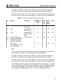
6. It is possible for the Promira I2C master to return an extended status code for
master read and master write transactions. These codes are described in Table 7
and are returned by the ps_i2c_read and ps_i2c_write functions, as well as
the analogous slave API functions.
Table 7 : I2C Extended Status Code
PS_I2C_STATUS_BUS_ERROR
A bus error has occurred. Transaction
was aborted.
PS_I2C_STATUS_SLA_ACK
Bus arbitration was lost during master
transaction; another master on the bus
has successfully addressed this Promira
Serial Platforms slave address. As a
result, this Promira adapter has
automatically switched to slave mode
and is responding.
PS_I2C_STATUS_SLA_NACK
The Promira application failed to receive
acknowledgment for the requested
slave address during a master
operation.
PS_I2C_STATUS_DATA_NACK
The last data byte in the transaction was
not acknowledged by the slave.
PS_I2C_STATUS_ARB_LOST
Another master device on the bus was
accessing the bus simultaneously with
this Promira Serial Platform. That device
won arbitration of the bus as per the I2C
specification.
49
Promira Platform User Manual
PS_I2C_STATUS_BUS_LOCKED
An I2C packet is in progress, and the
time since the last I2C event executed or
received on the bus has exceeded the
bus lock timeout. This is most likely due
to the clock line of the bus being held
low by some other device, or due to the
data line held low such that a start
condition cannot be executed by the
Promira application. The bus lock
timeout can be configured using the
ps_i2c_bus_timeout function. The
Promira application resets its own I2C
interface when a timeout is observed
and no further action is taken on the
bus.
PS_I2C_STATUS_LAST_DATA_ACK
When the I2C slave is configured with a
fixed length transmit buffer, it will detach
itself from the I2C bus after the buffer is
fully transmitted. The I2C slave also
expects that the last byte sent from this
buffer is NACKed by the opposing
master device. This status code is
returned by the I2C slave (see Slave
Write Statistics API) if the master device
instead ACKs the last byte. The
notification can be useful when
debugging a third-party master device.
These codes can provide hints as to why an impartial transaction was
executed by the Promira Serial Platform. In the event that a bus error
occurs while the Promira Serial Platform is idle and enabled as a slave
(but not currently receiving a message), the adapter will return the bus
error through the ps_i2c_slave_read function. The length of the
message will be 0 bytes but the status code will reflect the bus error.
5.6.2 General I2C
Free bus (ps_i2c_free_bus)
int ps_i2c_pullup (PromiraChannelHandle channel,
u08
ctrlId
u08
pullup_mask);
50
Promira Platform User Manual
Activate/deactivate I2C pull-up resistors on SCL and SDAFree the I2C subsystem from a
held.
Arguments
channel
handle of the channel
ctrlId
index of the subsystem
pullup_mask enumerated values specifying pullup state. See Table 8.
Table 8 : pullup_mask enumerated types
PS_I2C_PULLUP_NONE
Disable SCL/SDA pull-up resistors
PS_I2C_PULLUP_BOTH
Enable SCL/SDA pull-up resistors
PS_I2C_PULLUP_QUERY Queries the pull-up resistor state
Return Value
The current state of the I2C pull-up resistors on the Aardvark adapter will be
returned. The configuration will be described by the same values as in the table
above.
Specific Error Codes
None.
Details
Both pull-up resistors are controlled together. Independent control is not supported.
This function may be performed in any operation mode.
These pull-up resisters vary on the voltage level of SCL/SDA line which can be set
by ps_phy_level_shift. See Table 9
Table 9 : I2C pull-up resistor
Range of voltage
Pull-up resistor
<= 1.2V
389 ohm
> 1.2V and <= 2.2V 520 ohm
> 2.2V
1550 ohm
Free bus (ps_i2c_free_bus)
int ps_i2c_free_bus (PromiraChannelHandle channel,
51
Promira Platform User Manual
u08
ctrlId);
Free the I2C subsystem from a held bus condition (e.g., "no stop").
Arguments
channel
handle of the channel
ctrlId
index of the subsystem
Return Value
A status code is returned with PS_APP_OK on success.
Specific Error Codes
PS_I2C_BUS_ALREADY_FREE
The bus was already free and
no action was taken.
Details
If the I2C subsystem had executed a master transaction and is holding the bus due
to a previous PS_I2C_NO_STOP flag, this function will issue the stop command and
free the bus. If the bus is already free, it will return the status code
PS_I2C_BUS_ALREADY_FREE.
Similarly, if the I2C subsystem was placed into slave mode and in the middle of a
slave transaction, this command will disconnect the slave from the bus, flush the last
transfer, and re-enable the slave. Such a feature is useful if the Promira application
was receiving bytes but then was forced to wait indefinitely on the bus because of
the absence of the terminating stop command. After disabling the slave, any
pending slave reception will be available to the host through the usual
ps_i2c_slave_write_stats and ps_i2c_slave_read API calls.
The bus is always freed (i.e., a stop command is executed if necessary) and the
slave functions are disabled at software opening and closing of the device.
Set Bus Lock Timeout (ps_i2c_bus_timeout)
int ps_i2c_bus_timeout (PromiraChannelHandle channel,
u08
ctrlId,
u16
timeout_ms);
Set the I2C bus lock timeout in milliseconds.
Arguments
channel
handle of the channel
52
Promira Platform User Manual
ctrlId
index of the subsystem
timeout_ms
the requested bus lock timeout in ms.
Return Value
This function returns the actual timeout set.
Specific Error Codes
None.
Details
The power-on default timeout is 200ms. The minimum timeout value is 10ms and
the maximum is 450ms. If a timeout value outside this range is passed to the API
function, the timeout will be restricted. The exact timeout that is set can vary based
on the resolution of the timer within the Promira application. The nominal timeout
that was set is returned back by the API function.
If timeout_ms is 0, the function will return the bus lock timeout presently set on the
Promira application and the bus lock timeout will be left unmodified.
If the bus is locked during the middle of any I2C transaction (master transmit, master
receive, slave transmit, slave receive) the appropriate extended API function will
return the status code PS_I2C_STATUS_BUS_LOCKED as described in the
preceding Notes section. The bus lock timeout is measured between events on the I
2
C bus, where an event is a start condition, the completion of 9bits of data transfer,
a repeated start condition, or a stop condition. For example, if a full 9 bits are not
completed within the bus lock timeout (due to clock stretching or some other error),
the bus lock error will be triggered.
Please note that once the Promira application detects a bus lock timeout, it will abort
its I2C interface, even if the timeout condition is seen in the middle of a byte. When
the Promira application is acting as an I2C mater device, this may result in only a
partial byte being executed on the bus.
5.6.3 I2C Master
Set Bitrate (ps_i2c_bitrate)
int ps_i2c_bitrate (PromiraChannelHandle channel,
u08
ctrlId,
int
bitrate_khz);
Set the I2C bitrate in kilohertz.
53
Promira Platform User Manual
Arguments
channel
handle of the channel
ctrlId
index of the subsystem
bitrate_khz
the requested bitrate in khz.
Return Value
This function returns the actual bitrate set.
Specific Error Codes
None.
Details
The power-on default bitrate is 100 kHz.
Only certain discrete bitrates are supported by the I2C master interface. As such,
this actual bitrate set will be less than or equal to the requested bitrate.
If bitrate_khz is 0, the function will return the bitrate presently set on the I2C
subsystem and the bitrate will be left unmodified.
Queue a Set Bitrate (ps_queue_i2c_bitrate)
int ps_queue_i2c_bitrate (PromiraQueueHandle queue,
int
bitrate_khz);
Queue the command that sets the I2C bitrate in kilohertz.
Arguments
queue
handle of the queue
bitrate_khz
the requested bitrate in khz.
Return Value
A status code is returned with PS_APP_OK on success.
Specific Error Codes
None.
Details
54
Promira Platform User Manual
This function queues the command, it will be executed when the function
ps_queue_submit or ps_queue_async_submit is called.
The actual bitrate set will be returned with the function ps_collect_resp when
collecting.
Master Read (ps_i2c_read)
int ps_i2c_read (PromiraChannelHandle
u08
u16
PromiraI2CFlags
u16
u08 *
u16 *
handle,
ctrlId,
slave_addr,
flags,
num_bytes,
data_in
num_read);
Read a stream of bytes from the I2C slave device.
Arguments
channel
handle of the channel
ctrlId
index of the subsystem
slave_addr
the slave from which to read
flags
special operations as described in "Notes" section and below
num_bytes
the number of bytes to read (maximum 65535)
data_in
array into which the data read are returned
num_read
the actual number of bytes read
Return Value
Status code (see "Notes" section).
Specific Error Codes
PS_I2C_READ_ERROR
There was an error reading from the Promira
application. This is most likely a result of a
communication error.
Details
For ordinary 7-bit addressing, the lower 7 bits of slave_addr should correspond to
the slave address. The topmost bits are ignored. The I2C subsystem will assemble
the address along with the R/W bit after grabbing the bus. For 10-bit addressing, the
lower 10 bits of addr should correspond to the slave address. The I2C subsystem
will then assemble the address into the proper format as described in the Philips
55
Promira Platform User Manual
specification, namely by first issuing an write transaction on the bus to specify the
10-bit slave and then a read transaction to read the requested number of bytes. The
initial write transaction can be skipped if the "Combined Format" feature is
requested in conjunction with the 10-bit addressing functionality.
The data_in pointer should be allocated at least as large as num_bytes. When
the data_in is NULL, this function discards the actual received bytes and returns
only num_read. When the num_read is NULL, this function fills the actual received
bytes, but doesn't return the number of bytes received.
It is possible to read zero bytes from the slave. In this case, num_bytes is set to 0
and the data_in argument is ignored (i.e., it can be 0 or point to invalid memory).
However, due to the nature of the I2C protocol, it is not possible to address the slave
and not request at least one byte. Therefore, one byte is actually received by the
host, but is subsequently thrown away.
If the number of bytes read is zero, the following conditions are possible.
• The requested slave was not found.
• The requested slave is on the bus but refuses to acknowledge its address.
• The I2C subsystem was unable to seize the bus due to the presence of another
I2C master. Here, the arbitration was lost during the slave addressing
phase – results can be unpredictable.
• Zero bytes were requested from a slave. The slave acknowledged its address
and returned 1 byte. That byte was dropped.
Ordinarily the number of bytes read, if not 0, will equal the requested number of
bytes. One special scenario in which this will not happen is if the I2C subsystem
loses the bus during the data transmission due to the presence of another I2C
master.
If the slave has fewer bytes to transmit than the number requested by the master,
the slave will simply stop transmitting and the master will receive 0xff for each
remaining byte in the transmission. This behavior is in accordance with the I2C
protocol.
Additionally, the flags argument can be used to specify a sized read operation. If
the flag includes the value PS_I2C_SIZED_READ, the I2C subsystem will treat the
first byte received from the slave as a packet length field. This length denotes the
number of bytes that the slave has available for reading (not including the length
byte itself). The I2C subsystem will continue to read the minimum of num_bytes-1
and the length field. The length value must be greater than 0. If it is equal to 0, it will
be treated as though it is 1. In order to support protocols that include an optional
56
Promira Platform User Manual
checksum byte (e.g., SMBus) the flag can alternatively be set to
PS_I2C_SIZED_READ_EXTRA1. In this case the I2C subsystem will read one more
data byte beyond the number specified by the length field.
The status code allows the user to discover specific events on the I2C bus that
would otherwise be transparent given only the number of bytes transacted. The
"Notes" section describes the status codes.
For a master read operation, the PS_I2C_STATUS_DATA_NACK flag is not used
since the acknowledgment of data bytes is predetermined by the master and the I2C
specification.
Queue a Master Read (ps_queue_i2c_read)
int ps_queue_i2c_read (PromiraQueueHandle
u16
PromiraI2CFlags
u16
queue,
slave_addr,
flags,
num_bytes);
Queue a command that reads a stream of bytes from the I2C slave device.
Arguments
queue
handle of the queue
slave_addr
the slave from which to read
flags
special operations as described in "Notes" section and below
num_bytes
the number of bytes to read (maximum 65535)
Return Value
A status code is returned with PS_APP_OK on success.
Specific Error Codes
None
Details
This function queues the command, it will be executed when the function
ps_queue_submit or ps_queue_async_submit is called.
57
Promira Platform User Manual
The actual data read and the number of bytes read will be returned with the function
ps_collect_resp and ps_collect_i2c_read when collecting.
Collect a Master Read (ps_collect_i2c_read)
int ps_collect_i2c_read (PromiraCollectHandle
u16
u08 *
u16 *
collect,
num_bytes,
data_in
num_read);
Collect the response of I2C master read.
Arguments
collect
handle of the collection
num_bytes
maximum size of the array
data_in
array into which the data read are returned
num_read
the actual number of bytes read
Return Value
A status code is returned with PS_APP_OK on success.
Specific Error Codes
PS_APP_MISMATCHED_CMD
The type of response is not PS_I2C_CMD_READ.
Details
This function should be called right after the function ps_collect_resp returns
PS_I2C_CMD_READ. Once the function ps_collect_resp is called again, then
data for I2C read command will be discarded. However this function can be called
many times before the function ps_collect_resp is called.
Master Write (ps_i2c_write)
int ps_i2c_write (PromiraChannelHandle
u08
u16
PromiraI2CFlags
u16
const u08 *
u16 *
channel,
ctrlId,
slave_addr,
flags,
num_bytes,
data_out,
num_written);
Write a stream of bytes to the I2C slave device.
58
Promira Platform User Manual
Arguments
channel
handle of the channel
ctrlId
index of the subsystem
slave_addr
the slave from which to write
flags
special operations as described in "Notes" section
num_bytes
the number of bytes to write (maximum 65535)
data_out
pointer to data
num_written
the actual number of bytes written
Return Value
Status code (see "Notes" section).
Specific Error Codes
PS_I2C_WRITE_ERROR
There was an error reading the
acknowledgment from the Promira application.
This is most likely a result of a communication
error.
Details
For ordinary 7-bit addressing, the lower 7 bits of slave_addr should correspond to
the slave address. The topmost bits are ignored. The I2C subsystem will assemble
the address along with the R/W bit after grabbing the bus. For 10-bit addressing, the
lower 10 bits of addr should correspond to the slave address. The I2C subsystem
will then assemble the address into the proper format as described in the Philips
specification. There is a limitation that a maximum of only 65534 bytes can be
written in a single transaction if the 10-bit addressing mode is used.
The slave_addr 0x00 has been reserved in the I2C protocol specification for
general call addressing. I2C slaves that are enabled to respond to a general call will
acknowledge this address. The general call is not treated specially in the I2C
master. The user of this API can manually assemble the first data byte if the
hardware address programming feature with general call is required.
It is actually possible to write 0 bytes to the slave. The slave will be addressed and
then the stop condition will be immediately transmitted by the I2C subsystem. No
bytes are sent to the slave, so the data_out argument is ignored (i.e., it can be 0
or point to invalid memory).
If the number of bytes written is zero, the following conditions are possible.
• The requested slave was not found.
59
Promira Platform User Manual
• The requested slave is on the bus but refuses to acknowledge its address.
• The I2C subsystem was unable to seize the bus due to the presence of another
I2C master. Here, the arbitration was lost during the slave addressing
phase results can be unpredictable.
• The slave was addressed and no bytes were written to it because num_bytes
was set to 0.
The number of bytes written can be less than the requested number of bytes in the
transaction due to the following possibilities.
• The I2C subsystem loses the bus during the data transmission due to the
presence of another I2C master.
• The slave refuses the reception of any more bytes.
The status code allows the user to discover specific events on the I2C bus that
would otherwise be transparent given only the number of bytes transacted. The
"Notes" section describes the status codes.
For a master write operation, the PS_I2C_STATUS_DATA_NACK flag can be useful
in the following situation:
• Normally the I2C master will write to the slave until the slave issues a NACK or
the requested number of bytes have been written.
• If the master has wishes to write 10 bytes, the I2C slave issues either an ACK
or NACK on the tenth byte without affecting the total number of bytes
transferred. The status code will distinguish the two scenarios. This status
information could be useful for further communications with that particular slave
device.
Queue a Master Write (ps_i2c_read)
int ps_queue_i2c_write (PromiraQueueHandle
u16
PromiraI2CFlags
u16
const u08 *
queue,
slave_addr,
flags,
num_bytes,
data_out);
Queue a command that writes a stream of bytes to the I2C slave device.
Arguments
queue
handle of the queue
60
Promira Platform User Manual
slave_addr
the slave from which to write
flags
special operations as described in "Notes" section
num_bytes
the number of bytes to write (maximum 65535)
data_out
pointer to data
Return Value
A status code is returned with PS_APP_OK on success.
Specific Error Codes
None
Details
This function queues the command, it will be executed when the function
ps_queue_submit or ps_queue_async_submit is called.
The actual data written will be returned with the function ps_collect_resp and
ps_collect_i2c_write when collecting.
Collect a Master Write (ps_collect_i2c_write)
int ps_collect_i2c_read (PromiraCollectHandle collect,
u16 *
num_written);
Collect the response of I2C master write.
Arguments
collect
handle of the collection
num_written
the actual number of bytes written
Return Value
A status code is returned with PS_APP_OK on success.
Specific Error Codes
PS_APP_MISMATCHED_CMD
The type of response is not PS_I2C_CMD_READ.
Details
This function should be called right after the function ps_collect_resp returns
PS_I2C_CMD_WRITE. Once the function ps_collect_resp is called again, then
data for I2C write command will be discarded. However this function can be called
many times before the function ps_collect_resp is called.
61
Promira Platform User Manual
5.6.4 I2C Slave
Slave Enable (ps_i2c_slave_enable)
int ps_i2c_slave_enable (PromiraChannelHandle
u08
u08
u16
u16
channel,
ctrlId,
addr,
maxTxBytes,
maxRxBytes);
Enable the I2C subsystem as an I2C slave device.
Arguments
channel
handle of the channel
ctrlId
index of the subsystem
addr
address of this slave
maxTxBytes
max number of bytes to transmit per transaction
maxRxBytes
max number of bytes to receive per transaction
Return Value
A status code is returned with PS_APP_OK on success.
Specific Error Codes
None.
Details
The lower 7 bits of addr should correspond to the slave address of this I2C
subsystem. If the topmost bit of addr is set, the slave will respond to a general call
transmission by an I2C master. After having been addressed by a general call, the I2
C slave treats the transaction no differently than a single slave communication.
There is no support for the hardware address programming feature of the general
call that is described in the I2C protocol specification since that capability is not
needed for the Promira application.
If maxTxBytes is 0, there is no limit on the number of bytes that this slave will
transmit per transaction. If it is non-zero, then the slave will stop transmitting bytes
at the specified limit and subsequent bytes received by the master will be 0xff due
to the bus pull-up resistors. The response that is transmitted by the slave is set
through the ps_i2c_slave_set_response function described below. If the
maximum is greater than the response (as set through
62
Promira Platform User Manual
i2cc_slave_set_response) the I2C slave will wrap the response string as many
times as necessary to send the requested number of bytes.
If maxRxBytes is 0, the slave can receive an unlimited number of bytes from the
master. However, if it is non-zero, the slave will send a not-acknowledge bit after the
last byte that it accepts. The master should then release the bus. Even if the master
does not stop transmitting, the slave will return the received data back to the host
PC and then transition to a idle state, waiting to be addressed in a subsequent
transaction.
It is never possible to restrict a transmit or receive to 0 bytes. Furthermore, once the
slave is addressed by a master read operation it is always guaranteed to transmit at
least 1 byte.
If a master transaction is executed after the slave features have been enabled, the
slave features will remain enabled after the master transaction completes.
Slave Disable (ps_i2c_slave_disable)
int ps_i2c_slave_disable (PromiraChannelHandle channel,
u08
ctrlId);
Disable the I2C subsystem as an I2C slave device.
Arguments
channel
handle of the channel
ctrlId
index of the subsystem
Return Value
A status code is returned with PS_APP_OK on success.
Specific Error Codes
None.
Details
None.
Slave Set Response (ps_i2c_slave_set_response)
int ps_i2c_slave_set_response (PromiraChannelHandle channel,
u08
ctrlId,
u08
num_bytes,
63
Promira Platform User Manual
const u08 *
data_out);
Set the slave response in the event the I2C subsystem is put into slave mode and
contacted by a master.
Arguments
channel
handle of the channel
ctrlId
index of the subsystem
num_bytes
number of bytes for the slave response
data_out
pointer to the slave response
Return Value
The number of bytes accepted by the I2C subsystem.
Specific Error Codes
None.
Details
The value of num_bytes must be greater than zero. If it is zero, the response string
is undefined until this function is called with the correct parameters.
If more bytes are requested in a transaction, the response string will be wrapped as
many times as necessary to complete the transaction.
The buffer space is 64 bytes.
Asynchronous Polling (ps_i2c_slave_poll)
int ps_i2c_slave_poll (PromiraChannelHandle channel,
u08
ctrlId,
int
timeout);
Check if there is any asynchronous data pending from the I2C subsystem.
Arguments
channel
handle of the channel
ctrlId
index of the subsystem
timeout
timeout in milliseconds
Return Value
64
Promira Platform User Manual
A status code indicating which types of asynchronous messages are available for
processing. See Table 10.
Table 10 : Status code enumerated types
PS_I2C_SLAVE_NO_DATA
No asynchronous data is available.
PS_I2C_SLAVE_READ
I2C slave read data is available. Use function
ps_i2c_slave_read to get data.
PS_I2C_SLAVE_WRITE
I2C slave write stats are available. Use function
ps_i2c_slave_write_stats to get data.
PS_I2C_SLAVE_DATA_LOST
I2C slave data lost stats are available. Use
function ps_i2c_slave_data_lost_stats to
get data.
Specific Error Codes
None.
Details
Recall that, like all other Promira API functions, this function is not thread-safe.
If the timeout value is negative, the function will block indefinitely until data arrives. If
the timeout value is 0, the function will perform a non-blocking check for pending
asynchronous data.
This function sends a command to collect all slave data to I2C subsystem and saves
it I2C asynchronous slave queue. If there is any slave data in the queue, then it
returns the type of first slave data.
One can employ the following technique to guarantee that all pending asynchronous
slave data have been captured during each service cycle:
1. Call the polling function with a specified timeout.
2. If the polling function indicates that there is data available, call the appropriate
service function once for each type of data that is available.
3. Next, call the polling function with a 0 timeout.
4. Call the appropriate service function once for each type of data that is available.
5. Repeat steps 3 and 4 until the polling function reports that there is no data
available.
65
Promira Platform User Manual
Slave Write Statistics (ps_i2c_slave_write_stats)
int ps_i2c_slave_write_stats (PromiraChannelHandle
u08
u08 *
u16 *
channel,
ctrlId,
addr,
num_written);
Return number of bytes written from a previous Promira I2C slave to I2C master
transmission.
Arguments
channel
handle of the channel
ctrlId
index of the subsystem
addr
the address to which the sent message was received
num_written
the number of bytes written by the slave
Return Value
Status code (see "Notes" section).
Specific Error Codes
PS_I2C_SLAVE_TIMEOUT
There was no recent slave transmission.
PS_I2C_SLAVE_READ_ERROR
This slave data is not I2C slave write.
Details
The transmission of bytes from the Promira slave, when it is configured as an I2C
slave, is asynchronous with respect to the PC host software. Hence, there could be
multiple responses queued up from previous write transactions.
The only possible status code is PS_I2C_STATUS_BUS_ERROR which can occur
when an illegal START, STOP, or RESTART condition appears on the bus during a
transaction. In this case the num_written may not exactly reflect the number of
bytes written by the slave. It can be off by 1.
Slave Read (ps_i2c_slave_read)
int ps_i2c_slave_read (PromiraChannelHandle
u08
u08 *
u16
u08 *
channel,
ctrlId,
addr,
num_bytes,
data_in
66
Promira Platform User Manual
u16 *
num_read);
Read the bytes from an I2C slave reception.
Arguments
channel
handle of the channel
ctrlId
index of the subsystem
addr
the address to which the received message was sent
num_bytes
the maximum size of the data buffer
data_in
array into which the data read are returned
num_read
the actual number of bytes read by the slave
Return Value
Status code (see "Notes" section).
Specific Error Codes
PS_I2C_SLAVE_TIMEOUT
There was no recent slave transmission.
PS_I2C_DROPPED_EXCESS_BYTES
The msg was larger than num_bytes.
PS_I2C_SLAVE_READ_ERROR
This slave data is not I2C slave read.
Details
If the message was directed to this specific slave, *addr will be set to the value of
this slaves address. However, this slave may have received this message through a
general call addressing. In this case, *addr will be 0x80 instead of its own
address.
The num_bytes parameter specifies the size of the memory pointed to by data. It is
possible, however, that the received slave message exceeds this length. In such a
situation, PS_PS_I2C_DROPPED_EXCESS_BYTES is returned, meaning that
num_bytes was placed into data but the remaining bytes were discarded
There is no cause for alarm if the number of bytes read is less than num_bytes.
This simply indicates that the incoming message was short.
The reception of bytes by the Promira slave, when it is configured as an I2C slave, is
asynchronous with respect to the PC host software. Hence, there could be multiple
responses queued up from previous transactions.
The only possible status code is PS_I2C_STATUS_BUS_ERROR which can occur
when an illegal START, STOP, or RESTART condition appears on the bus during a
transaction.
67
Promira Platform User Manual
Slave Data Lost Statistics (ps_i2c_slave_data_lost_stats)
int ps_i2c_slave_data_lost_stats (PromiraChannelHandle channel,
u08
ctrlId);
Return number of slave read/write lost from a previous Promira I2C slave to I2C master
transmission.
Arguments
channel
handle of the channel
ctrlId
index of the subsystem
Return Value
The function returns the number of I2C slave read/write
Specific Error Codes
PS_I2C_SLAVE_TIMEOUT
There was no recent slave transmission.
PS_I2C_SLAVE_READ_ERROR
This slave data is not I2C slave data lost.
Details
There are two asynchronous slave queues, one in the host and the other is in the
device. When the capacity of both queues is all 255. If the number of slave data
exceeds 255 in the device, I2C slave read/write is counted as lost and returns back
to the host.
5.7 SPI Interface
5.7.1 SPI Notes
1. The SPI master and slave must both be configured to use the same bit protocol
(mode).
2. It is not necessary to set the bitrate for the Promira SPI slave.
3. An SPI master operation read or write operation can be transacted while leaving
the SPI slave functionality enabled. During the master transaction, the slave will
be temporarily deactivated. Once the master transaction is complete, the slave
will be automatically reactivated.
68
Promira Platform User Manual
4. It is always advisable to set the slave response before first enabling the slave.
This ensures that valid data is sent to any requesting master.
5. It is not possible to receive messages larger than approximately 64 KiB-1 as a
slave due to operating system limitations on the asynchronous incoming buffer.
As such, one should not queue up more than 64 KiB-1 of total slave data between
calls to the Promira API.
6. It is not possible to send messages larger than approximately 64 KiB-1 as a
master due to operating system limitations on the asynchronous incoming buffer.
The SPI is full-duplex so there must be enough buffer space to accommodate the
slave response when sending as a master.
7. Sending zero bytes as an SPI master will simply toggle the slave select line for
5-10 µs.
5.7.2 General SPI
Configure (ps_spi_configure)
int ps_spi_configure (PromiraChannelHandle
u08
PromiraSpiPolarity
PromiraSpiPhase
PromiraSpiBitorder
channel,
ctrlId,
polarity,
phase,
bitorder);
Configure the SPI master or slave interface.
Arguments
channel
handle of the channel
ctrlId
index of the subsystem
polarity
PS_SPI_POL_RISING_FALLING or
PS_SPI_POL_FALLING_RISING
phase
PS_SPI_PHASE_SAMPLE_SETUP or
PS_SPI_PHASE_SETUP_SAMPLE
bitorder
PS_SPI_BITORDER_MSB or PS_SPI_BITORDER_LSB
Return Value
A status code is returned with PS_APP_OK on success.
Specific Error Codes
None.
Details
69
Promira Platform User Manual
These configuration parameters specify how to clock the bits that are sent and
received on the Promira SPI interface.
The polarity option specifies which transition constitutes the leading edge and which
transition is the falling edge. For example, PS_SPI_POL_RISING_FALLING would
configure the SPI to idle the SCLK clock line low. The clock would then transition
low-to-high on the leading edge and high-to-low on the trailing edge.
The phase option determines whether to sample or setup on the leading edge. For
example, PS_SPI_PHASE_SAMPLE_SETUP would configure the SPI to sample on
the leading edge and setup on the trailing edge.
The bitorder option is used to indicate whether LSB or MSB is shifted first.
The pair ( PS_SPI_POL_FALLING_RISING, PS_SPI_PHASE_SETUP_SAMPLE )
would correspond to mode 3 in the figure found in the "SPI Background" chapter.
5.7.3 SPI Master
Set Bitrate (ps_spi_bitrate)
int ps_spi_bitrate (PromiraChannelHandle channel,
u08
ctrlId,
int
bitrate_khz);
Set the SPI bitrate in kilohertz.
Arguments
channel
handle of the channel
ctrlId
index of the subsystem
bitrate_khz
the requested bitrate in khz.
Return Value
This function returns the actual bitrate set.
Specific Error Codes
None.
Details
The power-on default bitrate is 1000 kHz.
70
Promira Platform User Manual
Only certain discrete bitrates are supported by the SPI subsystem. As such, this
actual bitrate set will be less than or equal to the requested bitrate unless the
requested value is less than 125 kHz, in which case the SPI subsystem will default
to 125 kHz.
If bitrate_khz is 0, the function will return the bitrate presently set on the Promira
application and the bitrate will be left unmodified.
Queue a Set Bitrate (ps_spi_bitrate)
int ps_queue_spi_bitrate (PromiraQueueHandle queue,
int
bitrate_khz);
Queue the command that sets the SPI bitrate in kilohertz.
Arguments
queue
handle of the queue
bitrate_khz
the requested bitrate in khz.
Return Value
A status code is returned with PS_APP_OK on success.
Specific Error Codes
None.
Details
This function queues the command, it will be executed when the function
ps_queue_submit or ps_queue_async_submit is called.
The actual bitrate set will be returned with the function ps_collect_resp when
collecting.
Set Slave Select Polarity (ps_spi_master_ss_polarity)
int ps_spi_master_ss_polarity (PromiraChannelHandle channel,
u08
ctrlId,
PromiraSpiSSPolarity polarity);
Change the output polarity on the SS line.
Arguments
71
Promira Platform User Manual
channel
handle of the channel
ctrlId
index of the subsystem
polarity
PS_SPI_SS_ACTIVE_LOW or PS_SPI_SS_ACTIVE_HIGH
Return Value
A status code is returned with PS_APP_OK on success.
Specific Error Codes
None.
Details
This function only affects the SPI master functions on the SPI subsystem. When
configured as an SPI slave, the SPI subsystem will always be setup with SS as
active low.
Queue a Set Slave Select Polarity (ps_spi_master_ss_polarity)
int ps_queue_spi_master_ss_polarity (
PromiraQueueHandle
queue,
PromiraSpiSSPolarity polarity);
Queue the command that changes the output polarity on the SS line.
Arguments
queue
handle of the queue
polarity
PS_SPI_SS_ACTIVE_LOW or PS_SPI_SS_ACTIVE_HIGH
Return Value
A status code is returned with PS_APP_OK on success.
Specific Error Codes
None.
Details
This function queues the command, it will be executed when the function
ps_queue_submit or ps_queue_async_submit is called.
Master Write/Read (ps_spi_write)
int ps_spi_write (PromiraChannelHandle channel,
72
Promira Platform User Manual
u08
u16
const u08 *
u16
u08 *
ctrlId,
out_num_bytes,
data_out,
in_num_bytes,
data_in);
Write a stream of bytes to the downstream SPI slave device and read back the fullduplex response.
Arguments
channel
handle of the channel
ctrlId
index of the subsystem
out_num_bytes
number of bytes to send
data_out
pointer to the bytes to transmit out
in_num_bytes
number of bytes to receive
data_in
array into which the data read are returned
Return Value
This function returns the total number of bytes read from the slave which normally
will be the same as the number of bytes written to the slave. See below for how this
value relates to in_num_bytes.
Specific Error Codes
PS_SPI_WRITE_ERROR
There was an error writing to the Promira
application. This is most likely a result of a
communication error. Make sure that
out_num_bytes is less than 64 KiB-1.
Details
Due to the full-duplex nature of the SPI protocol, for every byte written to the slave,
one byte is also received. The SPI subsystem will always receive the same number
of bytes that it sends out (barring any error). This is the return value mentioned
above. The user has the option of saving all, some, or none of those received bytes
by varying the size of in_num_bytes.
This function will always write out the number of bytes defined by out_num_bytes
from the memory pointed to by data_out. When out_num_bytes is larger than
in_num_bytes, data_in is completely filled and any extra bytes are dropped.
When out_num_bytes is less than in_num_bytes, all the received bytes are
saved and data_in is only partially filled.
73
Promira Platform User Manual
The data_in pointer should reference memory that is at least allocated to the size
specified by in_num_bytes. If data_in is NULL, then data received will be
discarded.
If out_num_bytes is 0, no bytes will be written to the slave. However, the slave
select line will be dropped for 5-10 µs. This can be useful in sending a signal to a
downstream SPI slave without actually sending any bytes. For example, if an SPI
slave has tied the slave select to an interrupt line and it sees the line is toggled
without any bytes sent, it can interpret the action as a command to prepare its
firmware for an subsequent reception of bytes. If out_num_bytes is 0, data_out,
data_in, and in_num_bytes can be set to 0.
If the return value of this function is less than out_num_bytes, there was an error.
SPI is a bit-blasting scheme where the master does not even know if there is a slave
on the other end of the transmission. Therefore, it is always expected that the
master will send the entire length of the transaction.
An error will likely occur if the number of bytes sent is significantly greater than
64 KiB-1. This function cannot reliably execute larger transfers due to the buffering
issues explained in the "Software | Application Notes" section. Only a partial number
of bytes will be sent to the slave and only a partial number will be received from the
slave; it is quite possible that these numbers will not be equal. The size of the partial
response is returned by this function and any received data up to in_num_bytes
will be in the memory pointed to by data_in. Note that the last few bytes of the
response may be corrupted as well.
Queue a Master Write/Read (ps_queue_spi_write)
int ps_queue_spi_write (PromiraQueueHandle queue,
u16
out_num_bytes,
const u08 *
data_out);
Queue the command that writes a stream of bytes to the downstream SPI slave device
and reads back the full-duplex response.
Arguments
queue
handle of the queue
out_num_bytes
number of bytes to send
data_out
pointer to the bytes to transmit out
Return Value
A status code is returned with PS_APP_OK on success.
74
Promira Platform User Manual
Specific Error Codes
None.
Details
This function queues the command, it will be executed when the function
ps_queue_submit or ps_queue_async_submit is called.
The actual data read and the number of bytes read will be returned with the function
ps_collect_resp and ps_collect_spi_write when collecting.
Collect a Master Write/Read (ps_collect_spi_write)
int ps_collect_spi_write (PromiraCollectHandle collect,
u16
in_num_bytes,
u08 *
data_in);
Collect the response of SPI master read.
Arguments
collect
handle of the collection
in_num_bytes
number of bytes to receive
data_in
array into which the data read are returned
Return Value
This function returns the total number of bytes read from the slave which normally
will be the same as the number of bytes written to the slave. See below for how this
value relates to in_num_bytes.
Specific Error Codes
PS_APP_MISMATCHED_CMD
The type of response is not
PS_SPI_CMD_WRITE.
Details
This function should be called right after the function ps_collect_resp returns
PS_SPI_CMD_WRITE. Once the function ps_collect_resp is called again, then
75
Promira Platform User Manual
data for SPI write/read command will be discarded. However this function can be
called many times before the function ps_collect_resp is called.
5.7.4 SPI Slave
Slave Enable (ps_spi_slave_enable)
int ps_spi_slave_enable (PromiraChannelHandle channel,
u08
ctrlId);
Enable the SPI subsystem as an SPI slave device.
Arguments
channel
handle of the channel
ctrlId
index of the subsystem
Return Value
A status code is returned with PS_APP_OK on success.
Specific Error Codes
None.
Details
None.
Slave Disable (ps_spi_slave_disable)
int ps_spi_slave_disable (PromiraChannelHandle channel,
u08
ctrlId);
Disable the SPI subsystem as an SPI slave device.
Arguments
channel
handle of the channel
ctrlId
index of the subsystem
Return Value
A status code is returned with PS_APP_OK on success.
Specific Error Codes
None.
76
Promira Platform User Manual
Details
None.
Slave Set Response (ps_spi_slave_set_response)
int ps_spi_slave_set_response (PromiraChannelHandle
u08
u08
const u08 *
channel,
ctrlId,
num_bytes,
data_out);
Set the slave response in the event the SPI subsystem is put into slave mode and
contacted by a master.
Arguments
channel
handle of the channel
ctrlId
index of the subsystem
num_bytes
number of bytes for the slave response
data_out
pointer to the slave response
Return Value
The number of bytes accepted by the SPI subsystem for the response.
Specific Error Codes
None.
Details
The value of num_bytes must be greater than zero. If it is zero, the response string
is undefined until this function is called with the correct parameters.
Due to limited buffer space on the SPI subsystem, the device may only accept a
portion of the intended response. If the value returned by this function is less than
num_bytes the SPI subsystem has dropped the remainder of the bytes.
If more bytes are requested in a transaction, the response string will be wrapped as
many times as necessary to complete the transaction.
77
Promira Platform User Manual
The buffer space will nominally be 64 bytes but may change depending on firmware
revision.
Asynchronous Polling (ps_spi_slave_poll)
int ps_spi_slave_poll (PromiraChannelHandle channel,
u08
ctrlId,
int
timeout);
Check if there is any asynchronous slave data pending from the SPI subsystem.
Arguments
channel
handle of the channel
ctrlId
index of the subsystem
timeout
timeout in milliseconds
Return Value
A status code indicating which types of asynchronous messages are available for
processing. See Table 10.
Table 10 : Status code enumerated types
PS_SPI_SLAVE_NO_DATA
No asynchronous slave data is available.
PS_SPI_SLAVE_DATA
SPI slave read data is available. Use
ps_spi_slave_read to get data.
PS_SPI_SLAVE_DATA_LOST
SPI slave data lost stats are available. Use
ps_spi_slave_data_lost_stats to get
data.
Specific Error Codes
None.
Details
This function is alike the function ps_i2c_slave_poll. However the SPI slave
data is separately handled and saved in the SPI asynchronous queue.
Slave Read (ps_spi_slave_read)
int ps_spi_slave_read (PromiraChannelHandle channel,
u08
ctrlId,
78
Promira Platform User Manual
u16
u08 *
num_bytes,
data_in);
Read the bytes from an SPI slave reception.
Arguments
channel
handle of the channel
ctrlId
index of the subsystem
num_bytes
the maximum size of the data buffer
data_in
array into which the data read are returned
Return Value
This function returns the number of bytes read asynchronously.
Specific Error Codes
PS_SPI_SLAVE_TIMEOUT
There was no recent slave transmission.
PS_SPI_DROPPED_EXCESS_BYTES
The data was larger than num_bytes.
PS_SPI_SLAVE_READ_ERROR
The slave data is not SPI slave data lost.
Details
The num_bytes parameter specifies the size of the memory pointed to by data. It is
possible, however, that the received slave message exceeds this length. In such a
situation, PS_SPI_DROPPED_EXCESS_BYTES is returned, meaning that num_bytes
was placed into data but the remaining bytes were discarded.
There is no cause for alarm if the number of bytes read is less than num_bytes.
This simply indicates that the incoming message was short.
The reception of bytes by the SPI subsystem, when it is configured as an SPI slave,
is asynchronous with respect to the PC host software. Hence, there could be
multiple responses queued up from previous write transactions.
The SPI API does not include a function that is analogous to the I2C function
ps_i2c_slave_write_stats. Since SPI is a full-duplex standard, the slave
writes to the master whenever it receives bytes from the master. Hence, a received
message from ps_i2c_slave_read implies that an equal number of bytes were
sent to the master.
Slave Data Lost Statistics (ps_spi_slave_data_lost_stats)
int ps_spi_slave_data_lost_stats (PromiraChannelHandle channel,
79
Promira Platform User Manual
u08
ctrlId);
Return number of slave read/write lost from a previous Promira SPI slave to SPI master
transmission.
Arguments
channel
handle of the channel
ctrlId
index of the subsystem
Return Value
The function returns the number of SPI slave read/write
Specific Error Codes
PS_SPI_SLAVE_READ_ERROR
The slave data is not SPI slave data lost.
Details
There are two asynchronous slave queues, one in the host and the other is in the
device. When the capacity of both queues is all 255. If the number of slave data
exceeds 255 in the device, SPI slave read/write is counted as lost and returns back
to the host.
5.8 GPIO Interface
5.8.1 GPIO Notes
1. The following enumerated type maps the named lines on the Promira I2C/SPI
output cable to bit positions in the GPIO API. All GPIO API functions will index
these lines through a single 8-bit masked value. Thus, each bit position in the
mask can be referred back its corresponding line through the mapping described
below.
Table 12 : PromiraGpioBits : enumerated type of line locations in bit mask
PS_GPIO_SCL
Pin 1 0x01 I2C SCL line
PS_GPIO_SDA
Pin 3 0x02 I2C SDA line
PS_GPIO_MISO Pin 5 0x04 SPI MISO line
PS_GPIO_SCK
Pin 7 0x08 SPI SCK line
PS_GPIO_MOSI Pin 8 0x10 SPI MOSI line
PS_GPIO_SS
Pin 9 0x20 SPI SS line
80
Promira Platform User Manual
2. There is no check in the GPIO API calls to see if a particular GPIO line is enabled
in the current configuration. If a line is not enabled for GPIO, the get function will
simply return 0 for those bits. Another example is if one changes the GPIO
directions for I2C lines while the I2C subsystem is still active. These new direction
values will be cached and will automatically be activate if a later call to
ps_app_configure disables the I2C subsystem and enables GPIO for the I2C
lines. The same type of behavior holds for ps_gpio_set.
3. Additionally, for lines that are not configured as inputs, a change in the GPIO line
using ps_gpio_set will be cached and will take effect the next time the line is
active and configured as an input.
4. On the Promira application launching, directions default to all input. Also the GPIO
subsystem is off by default. It must be activated by using ps_app_configure.
5.8.2 GPIO Interface
Direction (ps_gpio_direction)
int ps_gpio_direction (PromiraChannelHandle channel,
u32
direction_mask);
Change the direction of the GPIO lines between input and output directions.
Arguments
channel
handle of the channel
direction_mask
each bit corresponds to the physical line as given by
GpioBits. If a line's bit is 0, the line is configured
as an input. Otherwise it will be an output.
Return Value
A status code is returned with PS_APP_OK on success.
Specific Error Codes
None.
Details
None.
Get (ps_gpio_get)
int ps_gpio_get (PromiraChannelHandle channel);
81
Promira Platform User Manual
Get the value of current GPIO inputs.
Arguments
channel
handle of the channel
Return Value
An integer value, organized as a bitmask in the fashion described by GpioBits.
Any line that is logic high will have a its corresponding bit active. If the line is logic
low the bit will not be active in the bit mask.
Specific Error Codes
None.
Details
A line's bit position in the mask will be 0 if it is configured as an output or if it
corresponds to a subsystem that is still active.
Set (ps_gpio_set)
int ps_gpio_set (PromiraChannelHandle channel,
u32
value);
Set the value of current GPIO outputs.
Arguments
channel
handle of the channel
value
a bitmask specifying which outputs should be set to logic
high and which should be set to logic low.
Return Value
A status code is returned with PS_APP_OK on success.
Specific Error Codes
None.
Details
If a line is configured as an input or not activated for GPIO, the output value will be
cached. The next time the line is an output and activated for GPIO, the output value
previously set will automatically take effect.
82
Promira Platform User Manual
Change (ps_gpio_change)
int ps_gpio_change (PromiraChannelHandle channel,
u16
timeout_ms);
Block until there is a change on the GPIO input lines.
Arguments
channel
handle of the channel
timeout_ms
time to wait for a change in milliseconds
Return Value
The current state of the GPIO input lines.
Specific Error Codes
None.
Details
The function will return either when a change has occurred or the timeout expires.
Pins configured for I2C or SPI will be ignored. Pins configured as outputs will be
ignored. The timeout, specified in milliseconds, has a precision of approximately
2 ms. The maximum allowable timeout is approximately 60 seconds. If the timeout
expires, this function will return the current state of the GPIO lines. It is the
applications responsibility to save the old value of the lines and determine if there is
a change based on the return value of this function.
The function ps_gpio_change will return immediately with the current value of the
GPIO lines for the first invocation after any of the following functions are called:
ps_app_configure, ps_gpio_direction.
5.9 Error Codes
Table 13 : Promira API Error Codes
Literal Name
PS_APP_OK
Value ps_app_status_string() return value
0 ok
PS_APP_UNABLE_TO_LOAD_LIBRARY
-1 unable to load library
PS_APP_UNABLE_TO_LOAD_DRIVER
-2 unable to load USB driver
83
Promira Platform User Manual
PS_APP_UNABLE_TO_LOAD_FUNCTION
-3 unable to load binding function
PS_APP_INCOMPATIBLE_LIBRARY
-4 incompatible library version
PS_APP_INCOMPATIBLE_DEVICE
-5 incompatible device version
PS_APP_COMMUNICATION_ERROR
-6 communication error
PS_APP_UNABLE_TO_OPEN
-7 unable to open device
PS_APP_UNABLE_TO_CLOSE
-8 unable to close device
PS_APP_INVALID_HANDLE
-9 invalid device handle
PS_APP_CONFIG_ERROR
-10 configuration error
PS_APP_MEMORY_ALLOC_ERROR
-11 unable to allocate memory
PS_APP_UNABLE_TO_INIT_SUBSYSTEM
-12 unable to initialize subsystem
PS_APP_INVALID_LICENSE
-13 invalid license
PS_APP_PENDING_ASYNC_CMD
-30 pending respones to collect
PS_APP_TIMEOUT
-31 timeout to collect a response
PS_APP_CONNECTION_LOST
-32 connection lost
PS_APP_CONNECTION_FULL
-33 too many connections
PS_APP_QUEUE_FULL
-50 queue is full
PS_APP_QUEUE_INVALID_CMD_TYPE
-51 invalid command to be added
PS_APP_QUEUE_EMPTY
-52 no command to send
PS_APP_NO_MORE_TO_COLLECT
-80 no more response to collect
PS_APP_UNKNOWN_CMD
-81 unknown response received
PS_APP_MISMATCHED_CMD
-82 response doesn't match with the command
PS_I2C_NOT_AVAILABLE
-100 i2c feature not available
PS_I2C_NOT_ENABLED
-101 i2c not enabled
PS_I2C_READ_ERROR
-102 i2c read error
PS_I2C_WRITE_ERROR
-103 i2c write error
PS_I2C_SLAVE_BAD_CONFIG
-104 i2c slave enable bad config
PS_I2C_SLAVE_READ_ERROR
-105 i2c slave read error
PS_I2C_SLAVE_TIMEOUT
-106 i2c slave timeout
PS_I2C_DROPPED_EXCESS_BYTES
-107 i2c slave dropped excess bytes
PS_I2C_BUS_ALREADY_FREE
-108 i2c bus already free
PS_SPI_NOT_AVAILBLE
-200 spi feature not available
PS_SPI_NOT_ENABLED
-201 spi not enabled
PS_SPI_WRITE_ERROR
-202 spi write error
PS_SPI_SLAVE_READ_ERROR
-203 spi slave read error
84
Promira Platform User Manual
PS_SPI_SLAVE_TIMEOUT
-204 spi slave timeout
PS_SPI_DROPPED_EXCESS_BYTES
-205 spi slave dropped excess bytes
85
Promira Platform User Manual
6 Electrical Specifications
6.1 DC Characteristics
Table 14 : Absolute Maximum Ratings
Pin
Symbol
Conditions Min Max Units
1, 3, 9 SCL/GPIO-00, SDA/GPIO-01, SS/GPIO-05
-0.5
5.5
V
5, 7, 8 MISO/GPIO-02, SCK/GPIO-03, MOSI/GPIO-04
-0.5
4.6
V
Table 15 : Operating Conditions
Symbol Description
Conditions & Notes
Ta
Ambient Operating Temperature
Icore
Core Current Consumption
Min
Max
Units
10 (50) 35 (95) C (F)
(1)
500
mA
Notes:
(1) The core current consumption includes the current consumption for the entire internal
Promira platform, but does not include the outputs current consumption.
Table 16 : DC Characteristics
Pin
Symbol
4, 6
Conditions and Notes
Min
Max
Units
Vtgt
3.3
5
V
22, 24
IOVcc
0.9
3.45
V
1, 3, 9
SCL/GPIO-00, SDA/GPIO-01,
SS/GPIO-05
(1)
0.9
3.45
V
5, 7, 8
MISO/GPIO-02, SCK/GPIO-03,
MOSI/GPIO-04
(1)
0.9
3.45
V
4, 6
Vtgt
(2)
50
mA
22, 24
IOVcc
(2)
50
mA
1, 3, 9
SCL/GPIO-00, SDA/GPIO-01,
SS/GPIO-05
(3)
10
mA
5, 7, 8
MISO/GPIO-02, SCK/GPIO-03,
MOSI/GPIO-04
(3)
10
mA
Notes:
(1) The Level shifter precision is approximately 0.015V.
86
Promira Platform User Manual
(2) Option 1: Two pins have 50 mA each. Option 2: One pin has 100 mA, and one pin
has 0 mA. Etc. Total current consumption on both pins should not exceed 100 mA.
(3) Option 1: Six pins have 10 mA each. Option 2: One pin has 60 mA, and the other five
pins have 0 mA. Etc. Total current consumption on all six pins should not exceed 60 mA.
Table 17 : Current Consumption Calculation Example
Pin
Symbol
Description
Conditions &
Notes
Max
per
pin
Max
per all
pins
Units
NA
Icore
Core Current
Consumption
(1)
500
500
mA
4, 6
Vtgt
Configurable VCC
Power Supply
(2)
50
100
mA
22,
24
IOVcc
Configurable VCC
IO Level Power
Supply
(2)
50
100
mA
1, 3,
5, 7,
8, 9
SCL/GPIO-00, SDA/
I2C/SPI Signals
GPIO-01, MISO/GPIO-02,
SCK/GPIO-03, MOSI/
GPIO-04, SS/GPIO-05
(3)
10
60
mA
Total Current
Consumption For Promira
Core and Outputs
(4)
760
mA
Notes:
(1) The core current consumption includes the current consumption for the entire internal
Promira platform, but does not include the outputs current consumption.
(2) Option 1: Two pins have 50 mA each. Option 2: One pin has 100 mA, and one pin
has 0 mA. Etc. Total current consumption on both pins should not exceed 100 mA.
(3) Option 1: Six pins have 10 mA each. Option 2: One pin has 60 mA, and the other five
pins have 0 mA. Etc. Total current consumption on all six pins should not exceed 60 mA.
(4) If the total current consumption for the Promira platform core and outputs is over 500
mA, then USB 3.0 port and USB 2.0 cable or Total Phase external AC adapter should be
used. USB 3.0 port supplies up to 900 mA. USB 2.0 port supplies up to 500 mA. Total
Phase external AC adapter supplies up to 1.2 A. In this example the total current
87
Promira Platform User Manual
consumption for the Promira platform core and outputs is 760 mA, therefor USB 3.0 port
and USB 2.0 cable or Total Phase external AC adapter should be used.
6.2 AC Characteristics
6.2.1 SPI AC Characteristics
Table 18 (*) : SPI Timing Parameters
Symbol Parameter
Min
Max Units
t1
SS# assertion to first clock
0.5
20 (*)
µs
t2
Last clock to SS# deassertion
1
70 (*)
µs
tp
Clock period (clk)
80 10000
ns
td
Setup time (Master)
0
0.05
µs
td
Setup time (Slave)
0
n/a
µs
tb
Time between start of bytes (Slave)
8
n/a
clk
(*) - See also section 2.3.3.
Figure 12 : SPI Waveform
88
Promira Platform User Manual
Figure 13 : SPI Byte Timing
6.3 Signal Ratings
6.3.1 Logic High Levels
All signal levels are nominally 0.9-3.45 volts (+/- 10%) logic high. The Promira Serial
Platform is also compatible with devices with 5V I2C/SPI signals level.
6.3.2 ESD protection
The Promira Serial Platform has built-in electrostatic discharge protection to prevent
damage to the unit from high voltage static electricity.
6.3.3 Input Current
All I2C/SPI inputs (except for SPI SS signal) are high-impedance, and their input current
is approximately 1 µA. SS signal has 10k Ohm pull-up resistor. When SS signal is used
as input, its input current is approximately 1 µ.
89
Promira Platform User Manual
7 Legal / Contact
7.1 Disclaimer
All of the software and documentation provided in this manual, is copyright Total Phase,
Inc. ("Total Phase"). License is granted to the user to freely use and distribute the
software and documentation in complete and unaltered form, provided that the purpose
is to use or evaluate Total Phase products. Distribution rights do not include public
posting or mirroring on Internet websites. Only a link to the Total Phase download area
can be provided on such public websites.
Total Phase shall in no event be liable to any party for direct, indirect, special, general,
incidental, or consequential damages arising from the use of its site, the software or
documentation downloaded from its site, or any derivative works thereof, even if Total
Phase or distributors have been advised of the possibility of such damage. The software,
its documentation, and any derivative works is provided on an "as-is" basis, and thus
comes with absolutely no warranty, either express or implied. This disclaimer includes,
but is not limited to, implied warranties of merchantability, fitness for any particular
purpose, and non-infringement. Total Phase and distributors have no obligation to
provide maintenance, support, or updates.
Information in this document is subject to change without notice and should not be
construed as a commitment by Total Phase. While the information contained herein is
believed to be accurate, Total Phase assumes no responsibility for any errors and/or
omissions that may appear in this document.
7.2 Life Support Equipment Policy
Total Phase products are not authorized for use in life support devices or systems. Life
support devices or systems include, but are not limited to, surgical implants, medical
systems, and other safety-critical systems in which failure of a Total Phase product could
cause personal injury or loss of life. Should a Total Phase product be used in such an
unauthorized manner, Buyer agrees to indemnify and hold harmless Total Phase, its
officers, employees, affiliates, and distributors from any and all claims arising from such
use, even if such claim alleges that Total Phase was negligent in the design or
manufacture of its product.
7.3 Contact Information
Total Phase can be found on the Internet at http://www.totalphase.com/. If you have
support-related questions, please go to the Total Phase support page at http://
www.totalphase.com/support/. For sales inquiries, please contact [email protected]
.
90
Promira Platform User Manual
©2003-2014 Total Phase, Inc.
All rights reserved.
91