1
Regional Simulation Model (RSM)
Management Simulation Engine (MSE)
Version 2.2.9
Supervisors
Documentation and User Manual
South Florida Water Management District
Office of Modeling
Model Development Division (4540)
February 15 2005
Abstract
This document provides descriptions and documentation of supervisory control facilities implemented in the Management Simulation
Engine (MSE) component of the Regional Simulation Model (RSM).
1
Contents
1 Introduction
1.1 RSM Architecture . . . . . . . . . . . . . . . . . . . . . . . .
1.2 MSE Architecture . . . . . . . . . . . . . . . . . . . . . . . .
2 Supervisory Control of Controllers
2.1 Controller Functional Attributes . . . . .
2.1.1 General Controller Function XML
2.1.2 Fuzzy Controller Function XML .
2.1.3 Setpoint Controller Function XML
2.1.4 Sigmoid Controller Function XML
2.1.5 PID Controller Function XML . .
2.1.6 User Controller Function XML . .
2.1.7 LP Controller Function XML . . .
2.1.8 Alpha Controller Function XML .
2.2 Multiple Controller Selection . . . . . . .
2.2.1 Multiple Controller Selection XML
2.3 Controller Override . . . . . . . . . . . . .
2.3.1 Controller Override XML . . . . .
.
.
.
.
.
.
.
.
.
.
.
.
.
.
.
.
.
.
.
.
.
.
.
.
.
.
.
.
.
.
.
.
.
.
.
.
.
.
.
.
.
.
.
.
.
.
.
.
.
.
.
.
.
.
.
.
.
.
.
.
.
.
.
.
.
.
.
.
.
.
.
.
.
.
.
.
.
.
.
.
.
.
.
.
.
.
.
.
.
.
.
.
.
.
.
.
.
.
.
.
.
.
.
.
.
.
.
.
.
.
.
.
.
.
.
.
.
.
.
.
.
.
.
.
.
.
.
.
.
.
.
.
.
.
.
.
.
.
.
.
.
.
.
3 MSE Network
5
6
8
10
10
11
12
12
12
13
13
13
14
14
15
15
16
17
4 Input Variables
18
4.1 RSM Monitor Inputs . . . . . . . . . . . . . . . . . . . . . . . 18
4.2 XML Inputs . . . . . . . . . . . . . . . . . . . . . . . . . . . . 19
4.3 MSE Network Inputs . . . . . . . . . . . . . . . . . . . . . . . 20
5 Output Variables
21
6 Supervisor Monitors
22
7 Supervisors: General Usage
24
7.1 Global Supervisor On/Off . . . . . . . . . . . . . . . . . . . . 24
7.2 Supervisor Time Interval . . . . . . . . . . . . . . . . . . . . . 25
8 User Defined Supervisor
8.1 Implementation . . . . . . . . .
8.2 XML Interface . . . . . . . . .
8.2.1 user supervise attributes
8.2.2 ctrlID environment . . .
2
.
.
.
.
.
.
.
.
.
.
.
.
.
.
.
.
.
.
.
.
.
.
.
.
.
.
.
.
.
.
.
.
.
.
.
.
.
.
.
.
.
.
.
.
.
.
.
.
.
.
.
.
.
.
.
.
.
.
.
.
.
.
.
.
.
.
.
.
26
26
26
27
27
8.2.3 varIn attributes . . . . . . . . . . . .
8.2.4 varOut attributes . . . . . . . . . . .
8.3 User Supervisor Criteria . . . . . . . . . . .
8.4 User Supervisor Library Compilation . . . .
8.5 User Supervisor Initialization and Cleanup .
8.6 User Supervisor and Statically Linked HSE
8.7 C User Supervisor Interface . . . . . . . . .
8.8 C++ User Supervisor Interface . . . . . . .
8.9 C++ User Supervisor API functions . . . .
8.9.1 SetVarOut . . . . . . . . . . . . . .
8.10 User Defined Supervisor Example . . . . . .
.
.
.
.
.
.
.
.
.
.
.
.
.
.
.
.
.
.
.
.
.
.
.
.
.
.
.
.
.
.
.
.
.
.
.
.
.
.
.
.
.
.
.
.
.
.
.
.
.
.
.
.
.
.
.
.
.
.
.
.
.
.
.
.
.
.
.
.
.
.
.
.
.
.
.
.
.
.
.
.
.
.
.
.
.
.
.
.
28
28
29
29
30
30
31
32
33
33
35
9 Expert System Rule Based (Fuzzy) Supervisor
9.1 Fuzzy Supervisor Usage . . . . . . . . . . . . . .
9.1.1 fuz supervise attributes . . . . . . . . . .
9.1.2 ctrlID environment . . . . . . . . . . . . .
9.1.3 varIn attributes . . . . . . . . . . . . . . .
9.1.4 varOut attributes . . . . . . . . . . . . . .
9.2 Expert System Supervisor Example . . . . . . . .
.
.
.
.
.
.
.
.
.
.
.
.
.
.
.
.
.
.
.
.
.
.
.
.
.
.
.
.
.
.
.
.
.
.
.
.
.
.
.
.
.
.
40
41
42
42
42
43
44
10 GNU Linear Programming Kit (GLPK) Supervisor
10.1 GLPK MathProg Language . . . . . . . . . . . . . . .
10.2 GLPK Supervisor Usage . . . . . . . . . . . . . . . . .
10.2.1 id attribute . . . . . . . . . . . . . . . . . . . .
10.2.2 probFile solnFile outputFile attributes . . . . .
10.2.3 method attribute . . . . . . . . . . . . . . . . .
10.2.4 optimize attribute . . . . . . . . . . . . . . . .
10.2.5 presolve attribute . . . . . . . . . . . . . . . . .
10.2.6 msglevel attribute . . . . . . . . . . . . . . . .
10.2.7 timelimit attribute . . . . . . . . . . . . . . . .
10.2.8 outfreq . . . . . . . . . . . . . . . . . . . . . .
10.2.9 days hours minutes attribute . . . . . . . . . .
10.2.10 ctrlID environment . . . . . . . . . . . . . . . .
10.2.11 varIn attributes . . . . . . . . . . . . . . . . . .
10.2.12 varOut attributes . . . . . . . . . . . . . . . . .
10.3 GLPK Supervisor Example . . . . . . . . . . . . . . .
10.3.1 GLPK XML File . . . . . . . . . . . . . . . . .
.
.
.
.
.
.
.
.
.
.
.
.
.
.
.
.
.
.
.
.
.
.
.
.
.
.
.
.
.
.
.
.
.
.
.
.
.
.
.
.
.
.
.
.
.
.
.
.
.
.
.
.
.
.
.
.
.
.
.
.
.
.
.
.
49
49
50
51
52
52
52
52
52
53
53
53
53
54
55
56
57
3
.
.
.
.
.
.
.
.
.
.
.
.
.
.
.
.
.
.
.
.
.
.
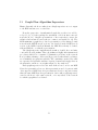
11 Graph Flow Algorithm Supervisor
59
11.1 Graph Flow Supervisor XML . . . . . . . . . . . . . . . . . . 60
11.1.1 graph supervise attributes . . . . . . . . . . . . . . . . 60
11.2 Graph Supervise Example . . . . . . . . . . . . . . . . . . . . 61
12 Object Routing Model-Assessor Supervisor
4
62
1
Introduction
The Regional Simulation Model (RSM) is a comprehensive hydrological
model intended to serve the numerical modeling needs of the South Florida
Water Management District. RSM incorporates an object-oriented design
approach, leveraging the inherent advantages of logical abstraction, inheritance, and hierarchical data object organization throughout the model. The
RSM consists of two interactive, primary components:
1. Hydrologic Simulation Engine (HSE)
2. Management Simulation Engine (MSE)
The HSE is a finite volume, coupled surface/groundwater/canal numerical model with full 2D and partial 3D flow capability. HSE includes structure flow equations for a wide variety of control structures, and implements
efficient numerical solutions of conjunctive hydrological simulations [1, 2, 3].
The MSE is designed to simulate the operational control characteristics encompassed by the wide spectrum of water flow control structures and
algorithms currently in use. The MSE is comprised of two primary subcomponents:
1. Controllers
2. Supervisors
The controllers are a suite of low-level control algorithms which serve as
flow regulators for individual structures. The controllers are defined within
the RSM XML model file <controller> tag environment, and are detailed
in a separate document [4]. The supervisors comprise a set of high-level supervisory control functions which provide dynamic controller modification
and coordination intended to facilitate regional control objectives. The supervisors therefore enable regional and subregional operational policy simulation in the RSM by interacting with, and controlling the behavior of
the watermover controllers. Each supervisor must be defined in the RSM
XML input file within the <management> tag environment. This document
provides development, implementation, and usage details for the MSE supervisors.
MSE is intended to provide two major modes of functionality in assisting
the hydrological modeler involved in analysis and prediction of water control
structure operational behaviors:
5
• Simulate existing water resource policies: Assessment of currently implemented management operational policies in response to hydrological forcing.
• Develop alternative resource control strategies through the optimization of operational policies.
The first task is a critical capability for the assessment of water control
operations in response to historic, real-time, or forecast forcing conditions.
In this mode the MSE modifies the behavior of the controllers to achieve a
predefined subregional or regional water resource allocation. Elucidation of
the imposed watermover flows can then be used to develop appropriate operational policies consistent with the available resources and desired objectives.
The latter facility forms an important analysis tool aimed at identification of
alternative operational policies which must perform complex, multi-variate,
resource allocation functions under the control of system boundary conditions and constraints. The MSE is formulated to address both of these
needs by providing a flexible, extensible, and interoperable suite of supervisory processors such as a rule-based expert system and a generic mathematical programming language interface which provides access to a suite of
state-of-the-art optimization algorithms.
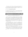
1.1
RSM Architecture
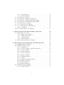
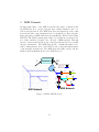
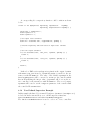
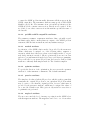
A schematic representation of the RSM information processing architecture
is depicted in figure 1. The HSE reads boundary condition information concerning the spatial characteristics of the model from the cell mesh (.2dm),
canal network (.map), and associated initial head and flow files. Input information also may be obtained from rainfall, ET, or other hydrological
process coverage/timeseries files. Based on this information HSE computes
flow and water levels for each component of the model at each timestep.
This comprises a set of state information (Σ), which describes the hydrological response of the system to the imposed boundary conditions and forcing
functions.
For the purposes of water management decisions, it may appropriate to
process the hydrological state information (Σ) with a variety of filters such as
spatio-temporal expectations, spatio-temporal integration/differentiation, or
timeseries amplitude or phase modulations. These operations are performed
by the Assessors and Filters. Assessors are specialized data processing algorithms suited to particular needs of water resource management, such as
assessing the water supply needs for a water control unit (WCU). Currently,
6
Λ
!"" "" # Σ
Σ
Figure 1: RSM Schematic
the Assessors are still in development, and are not documented. Refer to the
Benchmarks for the latest usage and implementations of Assessors. Filters
are generic data processors intended to provide common data preprocessing
functions such as scalar or timeseries amplitude modulation consisting of
the usual arithmetic operations (multiplication, division, addition, subtraction) or may compute simple timeseries or spatial variable statistics such as
arithmetic, geometric, or other expectations, or may act as an accumulator.
Information on filters may be found in the MSE Controllers Manual [4] in
section Data Monitor Filters.
The MSE accesses any raw, assessed, or filtered state information through
a <*monitor> interface. Based on the hydrological state information, as well
as any needed supervisory or control information, the MSE sets controller
variables for each supervised controller. The controller then modulates the
maximum available flow of the HSE watermover.
7
1.2
MSE Architecture
The MSE is tasked with a multi-dimensional objective function resolution
based on finite resource allocations and (possibly) interactive, multi-variate
constraint imposition. This task sounds complex, and it is. To achieve this
in a generalized, algorithmic independent implementation requires significant complexity in the design of the MSE. Nonetheless, it is intended that
utilization of industry standardized rule-base formulations, mathematical
programming language interpreters, and application specific heuristic supervisory algorithms can serve to isolate the modeler from such complexity.
Supervisor Controller Interface
Supervisors
S1
Processed f(Σ)
State
f(Σ)
Vector
S2
Χ1
Si
Χ2
Constraints
Objectives
SN
Χi
Λ
ΧN
Control Vector X
Controllers
Assessors
C2 C3 C4 C5
Ci CM
Control Output
Σ
State
Vector Σ
Σ
σ1
Controlled
WaterMover
HSE/MSE
Interface
State
Variable
σ2
q=Η(Σ,Χ)
Transfer
Function
Controlled
WaterMovers
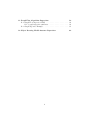
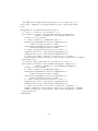
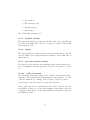
Figure 2: MSE Schematic
The MSE design approach is to allow multiple, independent supervisory control or objective optimization algorithms to run in parallel. The
supervisors are mapped to individual, or multiple controllers, providing a
high level of flexibility in the configuration of control policies. It is notable
that this design allows for the investigation of regional water policy management decisions with implicit consideration of fully coupled hydrological
flows and managed structure behaviors. A schematic representation of the
8
MSE information flow structure is shown in figure 2.
MSE will receive state information from the HSE, as well as constraint
and objective information (Λ) from the user defined inputs. MSE supervisors compute a control vector (X) which is applied to the appropriate
controllers. A supervisor is capable of controlling a single, or multiple controllers, and multiple controllers can be attached to a watermover, though
only one controller at a time can modulate the watermover.
It is relevant to note that this information processing scheme does not
specify, or rely upon a particular form of the control decision generator.
The implementation of a uniform interface between the supervisors and
controllers, and between the controllers and watermovers means that controllers and supervisors are interoperable, and may be dynamically switched.
This observation forms a core motivation for design of the MSE information
processing facilities as an algorithmic independent implementation. In this
manner, maximum extensibility and flexibility is retained for the application
of existing or future resource allocation or policy optimization schemes.
9
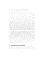
2
Supervisory Control of Controllers
The MSE supervisor is effectively a meta-controller, a controller of controllers. It is therefore important to understand the essential implementation details of the MSE controllers, significantly, the controllers are implemented as flow control regulators. The output of the controller is applied
as an amplitude scale factor to the computed flow of the watermover. The
intended range of controller outputs is in the interval of [0,1]. The user may
define the control output range for all of the controllers except the Sigmoid
controller. The user is strongly cautioned that implementation of controllers
with output control ranges outside of the interval [0,1] may result in unintended modulation of watermover flow values. The output control value
may be interpreted as a percentage of the total allowable structure flow.
MSE supervisors have the ability to change individual response characteristics of the MSE controllers, or, in the case of multiple controllers
attached to a watermover, to select and activate a specific controller for a
watermover. The available meta-control attributes for each controller are
described in section 2.1. However, it is notable that all controllers implement the control XML attribute which is used to activate/deactivate the
controller. If the value of control is set to any value other than ‘‘on’’, the
controller will be deactivated. This means that the control output will be
forced to a value of 1, no control output variations will occur. Since the control outputs are applied as amplitude modulation factors to the watermover
flow, the watermover flow will default to it’s uncontrolled values.
It is worth noting that there is a special ’controller’ dedicated solely
to Linear Programming (LP) supervisory control, the <lpctrl> controller.
The purpose of this controller is to provide a transparent interface from a LP
supervisory control variable to control of a watermover flow. The <lpctrl>
controller therefore has no control algorithm and does not process state
information. The <lpctrl> controller simply links a LP supervisor output
variable to a watermover flow such that the value of the supervisor output
variable directly scales (multiplies) the watermover flow value.
Description and implementation details of the MSE controllers can be
found in the MSE Controllers Manual [4].
2.1
Controller Functional Attributes
Each controller has specific attributes which may be controlled by the supervisor. The interface to these functions is specified with the func= attribute
of the <varOut> supervisor tag, see section 7. Generally, there is a func=
10
attribute which directly corresponds to an XML attribute of the controller
definitions. For example, the Setpoint controller has an attribute setlow=
as shown here:
<setpointctrl cid="125" wmID="25" label="S38 Culvert" setlow="0.">
The exact same effect can be achieved by the supervisor by specifying an
output variable with a value of 0 that is linked to the func="setLow". Sections 2.1.1 - 2.1.8 define the allowed functional attributes for each controller.
Refer to the RSM Controllers Manual [4] for descriptions of the individual
controller functional attributes.
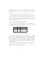
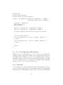
2.1.1
General Controller Function XML
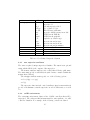
In addition to the controller specific functions, all controllers share some
common functions that can be controlled by the supervisor. These common
functions and values are shown in Table 2.1.1.
attribute
func=
controlOn
ctrlMin
ctrlMax
value
meaning
0 or 1
[0, 1]
[0, 1]
on or off
minimum output
maximum output
Table 2.1.1. Common Controller Functions
If the value of controlOn is set to any value other than 1, the controller
will be deactivated. This is directly analogous to the control=’off’ XML
attribute in the controllers XML definition. If the controller is deactivated,
the control output will be forced to a value of 1, no control output variations
will occur. Since the control outputs are applied as amplitude modulation
factors to the watermover flow, the watermover flow will default to it’s uncontrolled values.
The ctrlMin and ctrlMax attributes will set the minimum and maximum controller output limits. The user is cautioned to exercise care in
setting these values outside of the interval [0, 1].
11
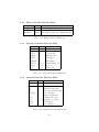
2.1.2
Fuzzy Controller Function XML
attribute
func=
newControl
FCLFile
value
meaning
0 or 1
string
reset controller
new FCL file name (Not Implemented)
Table 2.1.2. Fuzzy Controller Functions
2.1.3
Setpoint Controller Function XML
attribute
func=
setpoint
setlow
sethigh
triglow
trighigh
window
trigger
step
value
meaning
<
<
<
<
<
0, 1, 2
0 or 1
0 or 1
constant setpoint
low setpoint
high setpoint
low trigger
high trigger
outside, inside, all
off or on
down or up
Table 2.1.3. Setpoint Controller Functions
2.1.4
Sigmoid Controller Function XML
attribute
func=
offset
Gi
Gp
integral
c
scale
type
target
error
value
meaning
<
<
<
<
<
<
0 or 1
<
<
target offset
integral term gain
proportional term gain
error integral
sigmoid parameter
output scale factor
negative or positive
new target
error integral
Table 2.1.4. Sigmoid Controller Functions
12
2.1.5
PID Controller Function XML
attribute
func=
offset
Gi
Gd
Gp
integral
type
target
error
value
meaning
<
<
<
<
<
0 or 1
<
<
target offset
integral term gain
derivative term gain
proportional term gain
error integral
negative or positive
new target
error integral
Table 2.1.5. PID Controller Functions
2.1.6
User Controller Function XML
attribute
func=
newControl
module
func
value
meaning
0 or 1
shared object name
control function name
reset controller
string (Not Implemented)
string (Not Implemented)
Table 2.1.6. User Controller Functions
2.1.7
LP Controller Function XML
attribute
func=
ControlOut
TargetFlow
value
meaning
<
<
control value
LP desired flow (cfs)
Table 2.1.7. LP Controller Functions
13
2.1.8
Alpha Controller Function XML
attribute
func=
fullopen
alpha
offset
nvals
target
value
meaning
<
<
<
int
<
control cutoff
control parameter
target offset
no. integration points
new target
Table 2.1.8. Alpha Controller Functions
2.2
Multiple Controller Selection
Implementation of generic, nonlinear field controllers, such as those commonly employed by the District, may be difficult to achieve with a single
control algorithm per structure. The MSE controllers therefore support
the notion of ’controller overloading’. This means that more than one controller may be attached to a watermover. The intention is that separate
controllers with distinct control response characteristics may be enabled in
varying state-variable regimes suitable to each controller. For example, a
simple piecewise linear transfer function may be used under dry conditions,
while a rule based expert system (fuzzy) controller may be more effective in
flood conditions. A MSE supervisor can select and activate one of multiple
controllers attached to a watermover.
Note that the MSE to HSE controller interface does not allow multiple,
concurrent controllers to provide flow modulation commands to a watermover. Although multiple controllers may be attached to a watermover,
and can perform control algorithm computations concurrently (in the same
timestep) only one controller per timestep will have it’s control output applied to a watermover. It is the user’s responsibility to ensure that multiple
controllers are supervised accordingly.
When multiple controllers per watermover are initially parsed and created from the XML model file specifications, the first controller that is parsed
will be set as the active controller for the watermover. Subsequently, controllers that are encountered for the same watermover will replace the existing active watermover if the controller attribute control="on" is set.
Examples of a user defined supervisor activating single controllers from
multiple watermover controllers are shown in section 8.10.
14
2.2.1
Multiple Controller Selection XML
attribute
func=
controller
value
meaning
<
controller id > 0
Table 2.2.1. Multiple Controller Selection XML
2.3
Controller Override
It may be desirable for a supervisor to directly control the flow modulation
of a watermover. To accommodate this the supervisors are able to directly
’override’ the control computations of a watermover controller. This is done
with the use of the func="" attribute of a supervisor a <varOut> environment set to either func="controlOut" or func="override".
If the <varOut> specifies func="controlOut", then the controller output
will be replaced by the value of the supervisor <varOut>. As an example:
<varOut ctrlID="103" func="controlOut" name="Override"> </varOut>
The above <varOut> will force the controller to apply the output value of
the supervisor variable named "Override" to the watermover flow modulation. Setting func="controlOut" implicitly sets the override on for future
timesteps. The supervisor will continue to override the controller output
value until this feature is ’turned-off’. In order to turn-off (or turn-on) the
controller override, the supervisor implements a <varOut> which sets the
attribute func="override" and assigns it 0 for off, 1 for on. An example of
this usage is shown below.
<varOut ctrlID="103" func="override" name="OverrideOnOff"> </varOut>
The above <varOut> will activate the controller override for controller
ctrlID="103" if the value of <varOut name="OverrideOnOff"> evaluates
to non-zero. This assumes that a supervisor has previously activated a
controller override for this controller with the func="controlOut" attribute.
If the <varOut name="OverrideOnOff"> value evaluates to zero, then the
controller override is deactivated, and the control value computed by the
controller will be applied to the watermover modulation.
15
2.3.1
Controller Override XML
attribute
func=
override
controlOut
value
meaning
0, 1
<
0-off 1-on
control value
Table 2.3.1. Controller Override XML
16
3
MSE Network
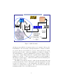
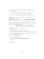
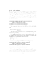
An important feature of the MSE in general is the usage of Assessors and
the MSE Network to provide synoptic state variable inputs for the controllers and supervisors. The MSE Network is an abstraction of the canal
network and water control structures based on graph theory. It provides implicit aggregation of HSE canal network segments into Water Control Units
(WCU’s). The WCU is an integrated data object which stores assessed values of state variables relevant to the collection of HSE segments. Through
the use of assessors and monitors, the controllers and supervisors access this
synoptic information. The MSE Network also contains information relevant to management policies of the WCU’s, and operational characteristics
of the structure watermovers. The MSE Network is fully described in the
RSM Controllers Manual [4] in section MSE Network.
Σ
f(Σ)
Assessors
<mse_node>
<mse_unit>
S11
S9
WCU1
S7
S8
WCU3
S3
WCU9
S4
WCU2
S10
WCU7
WCU10
WCU4
S5
S2
S6
WCU6
WCU5
WCU8
S1
MSE Network
HSE Network
Figure 3: HSE & MSE Network
17
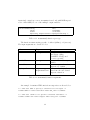
4
Input Variables
The <varIn> XML environment provides a generic interface for the multiinput variables accessed by MSE supervisors. The XML attributes and
environments supported by <varIn> are shown in Table 4.
environment
<varIn>
attribute
name
source
monitor
monID
monType
param
mse unit
unit attr
mse arc
arc attr
mse node
node attr
<scalar>
<vector>
<matrix>
meaning
input variable(s)
input variable name
input source
monitor specification
monitor ID
monitor type
parameter name for GLPK
MSE Network unit (WCU) name
MSE Network mse_unit attribute
MSE Network arc name
MSE Network mse_arc attribute
MSE Network node name
MSE Network mse_node attribute
single value XML input
multi value XML input
2D value XML input
Table 4. varIn Tags
The <varIn> environments define the state input(s) and provide a link
between the inputs defined in the XML file and the RSM state variables. The
name= argument defines a key which is used to access an input state variable.
Each <varIn> entry can have one of three source= attributes which defines
the source of the data input: "monitor", "xml" or "mse_network". The
default is source="monitor".
4.1
RSM Monitor Inputs
To input state information from a RSM monitor interface (i.e. <segmentmonitor>)
set the source="monitor", or omit the source= attribute. In this case the
varIn will have an associated <*monitor> entry. The monitor=, monID=
and monType= attributes must match the attributes of the associated state
<*monitor>. For example, the following are valid XML entries for a varIn
and monitor pair:
18
<varIn name="Segment1" monitor="segmentmonitor"
monID="1" monType="head"></varIn>
<segmentmonitor id="1" attr="head"></segmentmonitor>
However, if the monitor is a timekeeper monitor (<tkprmonitor>), the
monID= attribute is not used. The timekeeper monitor does not use the id
attribute as do the other state monitors. An example of this invocation
would be:
<varIn name="season" monitor="tkprmonitor"
monType="month"></varIn>
<tkprmonitor attr="month"></tkprmonitor>
4.2
XML Inputs
To define ’static’ input variables directly in the XML of the varIn, set
source="xml". Three variable formats are supported: scalar, vector, matrix. The scalar is simply a single data value. A vector is a one-dimensional
list of values, and the matrix is a two-dimensional table of columns and
rows. Within a single varIn environment one XML input variable environment may be created as shown below:
<varIn name="xmlScalar" source="xml">
<scalar> -325.43 </scalar>
</varIn>
<varIn name="xmlVector" source="xml">
<vector> -1.2 -3.4 -5.6 -7.8 -9.1 </vector>
</varIn>
<varIn name="xmlMatrix" source="xml">
<matrix> 1.2 3.4 ;
5.6 7.8 ;
9.1 2.3 ;
</matrix>
</varIn>
Vector datamembers are delimited by whitespace. Matrix columns (members of a row) are delimited by whitespace. Matrix rows are delineated by ’;’
or ’,’. All vector and matrix indices follow C/C++ semantics: 0 is the first
element. To access these members from a user defined supervisor, several
interface functions are provided as described in the MSE Controllers Manual [4] in section C++ User Controller API functions. The XML inputs are
currently only supported for C++ user defined controllers and supervisors.
19
4.3
MSE Network Inputs
The supervisor can also obtain input variables from objects of the MSE
Network (see section MSE Network of the MSE Controllers Manual [4]).
Any variable that is contained in an mse_unit, mse_arc or mse_node can be
accessed. Currently, only the User Defined supervisor is capable of accessing
these values through the use of API function calls. Sections C++ User
Controller API functions and MSE Network XML in the MSE Controllers
Manual [4] provide details and examples on the usage of these functions.
20
5
Output Variables
The varOut environment is used to couple the (possibly multiple) output of
a supervisor function to the appropriate controller or watermover. The XML
attributes and environments supported by <varOut> are shown in Table 5.
environment
<varOut>
attribute
ctrlID
wmID
func
name
<*monitor>
meaning
output variable(s)
controller ID
watermover ID
controller function
output variable name
State variable specification
Table 5. User Defined Supervisor System XML
Each varOut must have either the ctrlID or wmID defined, but not both.
The ctrlID is used when a supervisor is setting a controller attribute as described in section 2.1. The wmID is used only when a supervisor is selecting
a controller for activation on a watermover. For example, in the following
excerpt the first varOut is selecting a controller, while the second and third
are setting a controller functional attribute.
<varOut wmID="2" func="controller" name="s4_Controller"> </varOut>
<varOut ctrlID="103" func="triglow" name="103_TrigLow"> </varOut>
<varOut ctrlID="104" func="triglow" name="104_TrigLow"> </varOut>
The func attribute is used to specify which controller functional attribute is being modified. The allowed values of this attribute are described
in section 2.1. The name attribute must correspond to the name of the supervisor function in user defined modules, or to the output variable name
in the FCL file of fuzzy supervisors or the output variable name of a GLPK
supervisor. Refer to the section of a particular supervisor for usage and
examples of varOut.
21
6
Supervisor Monitors
MSE uses the <spvrmonitor> environment to monitor input state values fed
to the supervisors, or to monitor output values generated by supervisors. To
monitor controller I/O, and watermover variables, the user may resort to the
<ctrlmonitor> and <wmmonitor> environments respectively. These monitors are detailed in the MSE Controllers Manual [4] within the Watermover
Control & Maxflow Monitors, and the Controller Monitors sections. The
<spvrmonitor> attributes are shown in Table 6.
environment
<ctrlmonitor>
attribute
meaning
spvrID
attr
montype
var
ID of supervisor to be monitored
attribute to be monitored
type of variable: scalar, vector
variable name for type vector
Table 6. Supervisor Monitor XML
Each supervisor monitor must define a spvrID="" attribute of the
<spvrmonitor>. The spvrID attribute specifies supervisor id number of the
supervisor to be monitored. The spvrID must be a positive integer. The
other required attribute is the attr="". The attr="" may take one of two
values: "output" or "state", which are used for supervisor output and
input monitoring respectively.
Generally, supervisors are multi-input/multi-output (MIMO), though
they can be single-input/single-output. The montype="" attribute specifies whether the data stream is single or multi I/O by assignment of the
values scalar (default) or vector respectively. In the case of multi-inputs
or outputs, the var="" attribute is assigned the varIn or varOut name of
the corresponding variable.
Examples of supervisor monitors for output to dss files are shown below.
The first example outputs the supervisor output variable ctrl_103_TrigLow,
while the second entry writes the supervisor input variable segment1Head.
22
<output>
<spvrmonitor spvrID="801" attr="output"
montype="vector" var="ctrl_103_TrigLow" >
<dss file="t3x3out.dss" pn="/hse/spvr801/output//15min/calc1/">
</dss>
</spvrmonitor>
<spvrmonitor spvrID="801" attr="state"
montype="vector" var="segment1Head">
<dss file="t3x3out.dss" pn="/hse/spvr801/seg1_state//15min/calc1/">
</dss>
</spvrmonitor>
</output>
An example of a supervisor monitor is shown below for a User supervisor
that is monitoring the output value of another supervisor.
<user_supervise id="803" label="user_supervise1"
<varIn name="ctrl_101_" monitor="spvrmonitor"
monType="output"> </varIn>
<spvrmonitor spvrID="801" attr="output"
montype="vector" var="ctrl_101">
</user_supervise>
23
7
Supervisors: General Usage
The supervisors that are currently available within the MSE are:
• User Defined Finite State Machine, section 8
• Expert System Rule Base (Fuzzy), section 9
• Linear Programming Optimization, section 10
• Graph Flow Algorithm, section 11
• ORM, section 12
Each supervisor must be defined in the RSM XML input file in the
<management> environment. Within the <management> section, the supervisors are defined with appropriate XML specifications. The XML environments available for the MSE supervisors are shown in Table 7.
environment
<user_supervise>
<fuz_supervise>
<glpk_supervise>
<orm_supervise>
<graph_supervise>
meaning
User defined finite state machine
FCL rule-based expert system
GNU Linear Programming Kit
Object Routing Model
Graph theory flow algorithms
Table 7. MSE Supervisor XML
General supervisory control XML for activation/deactivation of supervisors, or conditional supervisor execution are described below in sections 7.1
and 7.2.
7.1
Global Supervisor On/Off
It may be advantageous to deactivate all supervisors with a single variable.
This is the function of the supervisors variable in the <control> section
of the XML input file. The default value is supervisors="on". If the value
is set to any value other than "on", all supervisors will be deactivated. The
supervisors will not influence the behavior of the controllers, the controllers
will operate according to their internal algorithms or rules. An example of
this usage is shown below.
24
<control
tslen="15"
tstype="minute"
startdate="01jan1994"
starttime="1200"
enddate="05jan1994"
endtime="0600"
alpha="0.500"
solver="PETSC"
method="gmres"
precond="ilu"
controllers="on"
supervisors="off">
</control>
7.2
Supervisor Time Interval
Execution of supervisory control may not be required at each timestep of
the simulation, in which case the user may specify a simulation time interval
which must elapse in order for the supervisor to be activated. This interval
is set within the supervisors XML tag specification via the attributes shown
in Table 7.2.
attribute
days
hours
minutes
type
int
int
int
meaning
number of days in interval
number of days in interval
number of minutes in interval
Table 7.2. MSE Supervisor XML
For example, to set the GLPK supervisor to run at simulation intervals
of 3 days, 2 hours and 1 minute, the following XML tag attributes can be
used:
<management id="1" label="RSM Supervisor">
<glpk_supervise id="801" label="glpk_supervise_1"
modelFile="glpk_mse1.mod" days="3" hours="2" minutes="1">
</glpk_supervise>
</management>
The default values are days="0" hours="0" minutes="0", which means
that the Supervisor algorithm will run at every timestep.
25
8
User Defined Supervisor
8.1
Implementation
The user supervisor provides a facility for the user to independently develop
a control algorithm applied to a controller/watermover. The user develops a
supervisory algorithm in C/C++, then compiles the control routine(s) into a
shared object library. The <user_supervise> implements a shared-library
loader and function pointer interface which calls the user-defined control
function(s) at each timestep. Each <user_supervise> will maintain it’s
own shared object and function pointer information, allowing the user to
define multiple supervisory functions inside a single shared object so that
individual supervisors may be enacted by selected functions which reside
inside a single shared object. It is also possible to define separate shared
objects for each supervisor. The user defined functions can take advantage
of several RSM application programming interface (API) functions to assist
in accessing input state variables and setting output values. The library
function interface is different for C++ and C libraries as described in the
following sections. User defined supervisor shared-object codes must include
the file mseIO.h.
8.2
XML Interface
Four information items have to be supplied to the supervisor for correct
coupling to the RSM state and control information:
1.
2.
3.
4.
controller id’s
input state variables
output control variables
shared library information
this is done with use of the XML attributes available for the user defined
supervisor shown in Table 8.2.
26
environment
<user_supervise>
attribute
meaning
id
label
libType
module
func
xml
graph
flow
days
hours
minutes
supervisor id
optional supervisor label
type of shared object
shared library path name
supervisor function name in module
MSE Network XML file
MSE Network graph file
graph theory solution type
supervise interval in days
supervise interval in hours
supervise interval in minutes
list of controller IDs
input variable(s)
output variable(s)
state variable to varIn
<ctrlID>
<varIn>
<varOut>
<*monitor>
Table 8.2. User Defined Supervisor System
8.2.1
user supervise attributes
The id is a required, unique supervisor identifier. The label is an optional
string which will label the outputs of the supervisor.
The module attribute must specify a valid shared library path name.
The func must specify a valid function symbol name contained within the
module shared library.
The libType attribute must specify one of the following options:
• C++ (Cpp c++ cpp)
• C (c)
The supervisor time interval control attributes (days hours minutes)
provide a mechanism to run the supervisor at selected intervals, see section
7.2.
8.2.2
ctrlID environment
The <ctrlID> environment defines a list of RSM controllers that will be
supervised. The values in this list must match a cid= attribute of a valid
controller definition. For example, if the following controller is defined:
27
<setpointctrl cid="125" wmID="25" label="S38 Culvert">
then a valid entry in the <ctrlID> list is 125. Each controller id in the list
should have at least one corresponding <varOut> entry which couples the
controller modifier with the corresponding function in the shared library. If
the supervisor is selecting a controller from among multiple controllers, then
there may not be a <varOut> for each entry in the <ctrlID> list.
8.2.3
varIn attributes
The <varIn> environments define the state input(s) and provide a link between the inputs defined in the shared library function and the RSM state
variables. The name= arguments define a key which is used in the userdefined function code to access input state variables. Refer to section 4
Input Variables for a description and usage of the <varIn> environment.
8.2.4
varOut attributes
The <varOut> attributes specify which controller is modified by which output variable linked to a shared library module function, or, to activate a
single controller for a watermover from among multiple controllers attached
to a watermover. Section 5 details the allowable XML entities for <varOut>.
In the case where a controller variable is to be changed, the ctrlID attribute
is used to specify the controller, the name defines the the output variable
function name in the shared library module, and the func specifies the controller variable to be changed. It is possible to have multiple <varOut>
entries for a single controller. For example, a supervisor may define three
<varOut> terms to modify the on/off, minimum output, and maximum output behaviors of a single controller. Each <varOut> would have a distinct
func and name entry. Section 2.1 describes the available func attributes for
each controller.
When a supervisor is used to activate a particular controller from among
multiple controllers attached to a watermover, the wmID attribute is used to
specify the affected watermover, the func="controller" must be set, and
the name defines the output variable function name in the shared library
module which will return a controller id number (positive integer) of the
controller to be activated.
28
8.3
User Supervisor Criteria
The following criteria apply to the <user_supervisor> shared library:
1. Ensure that the location of your library is included in the environment
variable LD_LIBRARY_PATH
2. The function must include the mseIO.h header file.
3. The function must include the state_mapIO.cc file to access MSE
API functions.
4. The function must return an integer value: 0 - success, nonzero - failure
5. C++ shared library functions must accept two input arguments, a
pointer to a C++ STL containter: map<string, InputState*>, and
a pointer to an map<string, OutputControl*>.
6. C shared library functions must accept six input arguments. First is
an integer, the number of variables. Second is an array of character
pointers, each array element listing an input variable name. Third
is an array of floating point double pointers, each reference is to the
current state of the corresponding input variable (with the same array
index) listed in the array of input variable names. Fourth is the integer
number of output variables, fifth an array of character pointers to
output variable names, and finally an array of floating point double
pointers, each reference to an output variable (with the same array
index) listed in the array of output variable names.
7. If you compile with a C++ compiler, declare the functions as extern "C"
to avoid name mangling in the shared object.
8.4
User Supervisor Library Compilation
To convert C++ code into a shared object with the name UserSpvr.so,
assuming that the function is in a file named userspvr.cc, the following command can be used in Linux:
gcc userspvr.cc -Bsymbolic -shared -o UserSpvr.so
29
8.5
User Supervisor Initialization and Cleanup
If the user desires to have a one-time initialization call, and one-time cleanup
call made to the library at the time the library is loaded and unloaded
respectively, the user must define two functions within the library:
1. void _init() { };
2. void _fini() { };
The _init() function will be called after the shared library loader successfully imports the shared library, and the _fini() function will be called
before the library is unloaded. To prevent linkage conflicts with common
standard library functions, add the -nostdlib argument to the compiler command:
gcc userspvr.cc -Bsymbolic -shared -o UserSpvr.so -nostdlib
8.6
User Supervisor and Statically Linked HSE
The current version of RSM does not support user defined supervisors developed in C++ if the RSM is statically linked. If the RSM is dynamically
linked, then C++ user defined shared libraries are supported.
30
8.7
C User Supervisor Interface
If the shared library is developed in C, the supervisor functions are called
from the MSE with six input variables as shown in the prototype below:
int MySupervise (int
varInNum,
char **varInNames,
double *varInValues,
int
varOutNum,
char **varOutNames,
double *varOutValues);
Table 8.7. C user supervisor function prototype
The first argument is an integer which defines the number of input
variables being passed to the function. This corresponds to the number
of <varIn> variables defined within the <user_supervise> section of the
xml file. The second argument is an array of character strings. Each
array element contains the name of an input variable as defined in the
<varIn name=""> section of the xml file. The third argument is an array of floating point (double) values, which contain the current numerical
values of the state variables. The array indices of the second and third
arguments match on a one-to-one correspondence. That is, for the variable with the name varInNames[2], the current state value is contained in
varInValues[2].
The fourth argument is the number of output variables, which corresponds to the number of <varOut> variables defined within the <user_supervise>
section of the xml file. The fifth argument is an array of character strings.
Each array element contains the name of an output variable as defined in
the <varOut name=""> section of the xml file. The sixth argument is an array of floating point (double) values, which are used to contain the output
value computed by the supervisor. The array indices of the fifth and sixth
arguments match on a one-to-one basis. That is, for the variable with the
name varOutNames[2], the output value is set into varOutValues[2].
The fact that the user has to properly track and access these I/O pointers
makes the C function interface hazardous. It is safer and less error-prone to
rely on the C++ user interface wherein the assignment of <varOut> values
is performed with a function call to the API function SetVarOut(), refer to
section 8.9.1.
31
The supervisor functions must return an integer (int) status value. A
value of 0 indicates no error, a non-zero return value indicates that an error
has occurred in the supervisor function, in which case a MseError exception
will be thrown, and the simulation terminated.
8.8
C++ User Supervisor Interface
User defined supervisors developed in C++ receive two input variables which
are pointers to an inputStateMap, and an outputControlMap associative
array as illustrated in the following prototype.
extern "C" int MySupervise( map<string, InputState*>
*lpISMap,
map<string, OutputControl*> *lpOCMap );
Table 8.8. C++ user supervisor function prototype
The C++ map pointed to by lpISMap contains pointers to InputState
classes, one pointer for each varIn variable defined in the supervisor XML
file. The map key to each pointer is the variable name (varIn="") as defined
in the userspvr section of the XML file. To access an input state variable
the supervisor function calls the GetVarIn() API function as described in
section GetVarIn in the MSE Controller Manual. The definition of the
InputState structure can be found in the C++ source file: mseIO.h, which
is a required header file.
In an analogous fashion, the C++ map pointed to by lpOCMap contains
pointers to OutputControl classes, one pointer for each varOut variable defined in the supervisor XML file. The map key to each pointer is the variable
name (varOut="") as defined in the userspvr section of the XML file. To
assign an output value the supervisor function calls the SetVarOut() API
function as described in section 8.9.1. The definition of the OutputControl
structure can be found in the C++ source file: mseIO.h.
The C++ supervisors must return an integer value. A return value of
0 indicates no error occurred in the supervisor function. A non-zero return
value indicated that an error occurred in the user supervisor function. In this
case an MseError exception is thrown by the MSE, ending the simulation.
An example of a user defined supervisor function interface is shown below.
32
#include <map>
#include "hse/src/mseIO.h"
#include "hse/mse_tools/state_mapIO.cc"
extern "C" int MySupervise( map<string, InputState*>
*lpISMap,
map<string, OutputControl*> *lpOCMap ) {
string func = "MySupervise";
double spvrOut1 = 0.;
double spvrOut2 = 0.;
double h1 = GetVarIn( func, "segment1Head", lpISMap );
double h2 = GetVarIn( func, "segment4Head", lpISMap );
// Provide supervsory function based on input state variable
....
// Set the output variables
if ( not SetVarOut( func, "ctrl_101", spvrOut1, lpOCMap ) ) {
return -1;
}
if ( not SetVarOut( func, "ctrl_102", spvrOut2, lpOCMap ) ) {
return -1;
}
return 0;
}
8.9
C++ User Supervisor API functions
MSE provides a set of API functions to be used for the access of input state
variables, setting of output state variables, and accessing data members from
the MSE Network. With the exception of the SetVarOut function, all user
API functions can be used from a controller as well as a supervisor. For this
reason, the API functions are documented in the MSE Controllers Manual
[4] in section C++ User Controller API functions.
8.9.1
SetVarOut
To set the value of an output variable from a user defined supervisor, the supervisory function makes a call to the SetVarOut function. The SetVarOut
function is not used with MSE controllers, as the controllers are MISO (multi
33
input single output) processors. SetVarOut is used only with MSE supervisors to individually set one of the multiple output variables.
int SetVarOut(string
func,
string
varOutName,
double
controlOut,
map<string, OutputControl*> *lpOutputControlMap );
Table 8.9.1. SetVarOut() function prototype
The function returns an integer value of either 0 (failure) or 1 (success).
The input arguments are described below.
Name
func
Type
string
varOutName
string
controlOut
double
lpOutputControlMap
*map<string,
OutputControl*>
Description
name of function in
user library calling
GetMSENodeVal(), used
for error reporting
name of the varOut output
variable
numeric output value of
supervisor to varOut
pointer to the OutputControlMap
passed into the user defined
supervisor function
Table 8.9.1. SetVarOut() function arguments
An example of <varOut> XML entries from a supervisor are shown below.
<!-- This uses wmID to specify a controller via cid output -->
<varOut wmID="1" func="controller" name="wm1_ctrl"> </varOut>
<!-- This uses ctrlID to set specific controller attributes -->
<varOut ctrlID="102" func="triglow" name="ctrl_102"> </varOut>
34
A corresponding C++ supervisory function could be written as shown
below.
extern "C" int MySupervise( map<string, InputState*>
*lpISMap,
map<string, OutputControl*> *lpOCMap ) {
string func = "MySupervise";
double spvrOut1 = 0.;
double spvrOut2 = 0.;
// Get input state variables
double h1 = GetVarIn( func, "segment1Head", lpISMap );
double h2 = GetVarIn( func, "segment4Head", lpISMap );
// Provide supervsory function based on input state variable
....
// Set the output variables
if ( not SetVarOut( func, "wm1_ctrl", spvrOut1, lpOCMap ) ) {
return -1;
}
if ( not SetVarOut( func, "ctrl_102", spvrOut2, lpOCMap ) ) {
return -1;
}
return 0;
}
In the above XML section and supervisory function, the output of varOut
with name="ctrl_102" is used to dynamically assign a controller to the watermover with ID wmID="1". The value of the variable spvrOut1 in the
function MySupervise will be converted to an integer, the controller which
has an ID matching the integer value of spvrOut1 will be set as the active controller for the watermover with ID wmID="1". The second output,
spvrOut2 will be used to set the "triglow" parameter of the controller with
the controller ID ctrlID="102".
8.10
User Defined Supervisor Example
In this example the shared object named UserSprv.so (module="./UserSprv.so")
is loaded from the current directory to call the supervisor functions:
func="SetWM1Controller" and func="SetWM1CtrlTriggers".
The function SetWM1Controller is used to select one of two controllers
35
(cid="101" or cid="101") for the watermover with wmID="1". The function
"SetWM1CtrlTriggers" will set the lower trigger threshold value (triglow)
for the controllers.
These functions will receive two input state values named segment1Head
and segment4Head. The state variables will reside in an InputStateMap,
with keys segment1Head and segment4Head, which are used to access the
input values through the GetVarIn() API function. The two controllers
attached to watermover 1 are simple linear transfer function (setpoint) controllers. Refer to the Setpoint Controllers section of the MSE Controller
Manual [4] for complete descriptions of the controller parameters. The XML
controller definitions for this example are:
<controller id="1">
<!-- Multiple controllers per watermover are defined
-->
<!-- The first controller parsed will be set as the active controller -->
<!-- Any subsequent controller with control="on" will become the
-->
<!-- active controller for the watermover.
-->
<!-- To change the active controllers, the supervisor must assign
-->
<!-- another controller
-->
<!-- Controller for discharge from segment 1 -->
<setpointctrl cid="101" label="SPCtrl 1: " wmID="1" window="all" control="on"
setlow="0.0" sethigh="1.0" triglow="500.0" trighigh="505.0" trigger="on">
<segmentmonitor id="1" attr="head"></segmentmonitor>
</setpointctrl>
<!-- Controller for discharge from segment 1 -->
<setpointctrl cid="102" label="SPCtrl 1A: " wmID="1" window="all" control="on"
setlow="0.0" sethigh="0.5" triglow="495.0" trighigh="500.0" trigger="on">
<segmentmonitor id="1" attr="head"></segmentmonitor>
</setpointctrl>
</controller>
36
The XML section which defines the supervisors to select the active controller, and to adjust the lower trigger threshold of the controllers is shown
below:
<management id="1" label="user-multi-control">
<!-- Select a controller for watermover 1 -->
<user_supervise id="801" label="SetWM1Controller" libType="C++"
module="./UserSprv.so" func="SetWM1Controller">
<ctrlID> 101 102 </ctrlID>
<!-- Input variables to SetWM1Controller -->
<varIn name="segment1Head" monitor="segmentmonitor"
monID="1" monType="head"> </varIn>
<varIn name="segment4Head" monitor="segmentmonitor"
monID="4" monType="head"> </varIn>
<!-- Input variable monitors from hse to varIn -->
<segmentmonitor id="1" attr="head"></segmentmonitor>
<segmentmonitor id="4" attr="head"></segmentmonitor>
<!-- This uses wmID to specify a controller via cid output -->
<varOut wmID="1" func="controller" name="segment1_Controller"> </varOut>
</user_supervise>
<!-- Set the triglow threshold for controllers 101 & 102 -->
<user_supervise id="803" label="SetWM1CtrlTriggers" libType="C++"
module="./UserSprv.so" func="SetWM1CtrlTriggers">
<ctrlID> 101 102 </ctrlID>
<!-- Input variables to SetWM1CtrlTriggers -->
<varIn name="segment1Head" monitor="segmentmonitor"
monID="1" monType="head"> </varIn>
<varIn name="segment4Head" monitor="segmentmonitor"
monID="4" monType="head"> </varIn>
<!-- Input variable monitors from hse to varIn -->
<segmentmonitor id="1" attr="head"></segmentmonitor>
<segmentmonitor id="4" attr="head"></segmentmonitor>
<!-- These use ctrlID to set specific controller attributes -->
<varOut ctrlID="101" func="triglow" name="ctrl_101_TrigLow"> </varOut>
<varOut ctrlID="102" func="triglow" name="ctrl_102_TrigLow"> </varOut>
</user_supervise>
</management>
37
To compile this example code into a shared library named UserSprv.so
on a Linux platform:
gcc usersprv.cc -BSymbolic -shared -o UserSprv.so
The c++ code for each of the supervisor functions is shown below.
#include
#include
#include
#include
<cstdio> // include if you want to use C-style printf
<map>
"hse/src/mseIO.h"
// THIS FILE MUST BE INCLUDED
"hse/mse_tools/state_mapIO.cc" // THIS FILE MUST BE INCLUDED
//--------------------------------------------------------------------// Function SetWM1Controller for selection of watermover 1 controllers
//--------------------------------------------------------------------extern "C" double SetWM1Controller(
map<string, InputState*>
*lpInputStateMap,
map<string, OutputControl*> *lpOutputControlMap ) {
int status = 0;
double superviseOut = 0.; // output value
// Get the current state value for each variable
double segment1Head = GetVarIn( func, "segment1Head", lpInputStateMap );
// Select controller id (101 or 102) based on input state variable
if (...) { superviseOut = 101 }
else (...) { superviseOut = 102 }
// Set the output variable
if ( not SetVarOut( func, "segment1_Controller",
controlOut, lpOutputControlMap ) ) {
status = -1;
}
return status;
}
38
//--------------------------------------------------------------------// Function SetWM1CtrlTrigger
//--------------------------------------------------------------------extern "C" double SetWM1CtrlTriggers(
map<string, InputState*> *lpInputStateMap,
map<string, OutputControl*> *lpOutputControlMap ) {
int status = 0;
double superviseOut = 0.; // output value
// Get the current state value for each variable
double segment1Head = GetVarIn( func, "segment1Head", lpInputStateMap );
// Provide control function
if (...)
{ controlOut
else if (...) { controlOut
else
{ controlOut
based on input state variable
= 495.; }
= 498.; }
= 500.; }
if ( not SetVarOut( func, "ctrl_101_TrigLow",
controlOut, lpOutputControlMap ) ) {
status = -1;
}
return status;
}
39
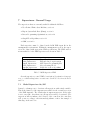
9
Expert System Rule Based (Fuzzy) Supervisor
The ability to simulate application of operational rules to water control
structures on a regional scale is an important requirement of the MSE. This
feature enables the RSM to simulate the actual operational policies in response to historical, real-time, or forecast forcing events beyond the scope
of individual control structures which are acting solely to achieve a local
objective. Over the span of many years, District personnel have amassed
a large and complex knowledge base of operational control guidelines and
rules. Application of this knowledge in response to situational environmental conditions constitutes an expert system which optimizes the regional
hydrological responses under the constraints imposed by flood control, water supply and environmental concerns. It is therefore important that a
natural and efficient mechanism is employed by the MSE to allow for incorporation of expert system control. The MSE achieves this by use of
a multi-input, multi-output characteristic field controller, which is implemented according to the International Electrotechnical Commission (IEC)
Technical Committee on Industrial Process Measurement and Control, Programmable Controllers [9]. It relies upon a user-defined set of input/output
variables, and rules which map the variables to the control functions.
It is important that the format of the rules do not rely upon an obscure
or difficult to understand syntax which decouples the natural expression of
the existing knowledge base from that of the MSE implementation. For
example, if the published guideline for a structure is: “If the upstream head
at structure A1 is high, then open the gate” then the corresponding rule in
the expert system management should read roughly the same. The obvious
way to achieve this is to apply the principles of linguistic processing, which
have led to the development of the Fuzzy Control Language (FCL). The
FCL provides a natural, common-language interface to the implementation
of a nonlinear characteristic field controller, and is ideal for this purpose.
The RSM controllers include a fuzzy controller, which resides in an RSM
library developed by the Model Development Division. The MSE leverages
on the independent control functionality of the FCL library, and uses it to
enact a multi-controller supervisory agent.
40
9.1
Fuzzy Supervisor Usage
The Expert System Supervisor (fuz_supervise) relies on a user-supplied
knowledge base to enact controller supervision. Four information items have
to be supplied to the supervisor for correct coupling to the RSM state and
control information:
1.
2.
3.
4.
controller id’s
input state variables
output control variables
rule base
this is done by use of the XML attributes available for the rule-based
expert system (fuz_supervise) shown in Table 9.1.
environment
<fuz_supervise>
attribute
meaning
id
label
fcl
days
hours
minutes
supervisor id
optional supervisor label
name of FCL rule file
supervise interval in days
supervise interval in hours
supervise interval in minutes
list of controller IDs
input variable(s)
input variable name
monitor specification
monitor ID
monitor type
output variable(s)
controller ID
watermover ID
controller function
output variable name
State variable specification
<ctrlID>
<varIn>
name
monitor
monID
monType
<varOut>
ctrlID
wmID
func
name
<*monitor>
Table 9.1. Rule-based Expert System
41
9.1.1
fuz supervise attributes
The id is a unique supervisor identifier, label is an optional string which
will label the outputs of the supervisor. The fcl attribute must specify
a valid FCL definition file. The supervisor time interval control attributes
(days hours minutes) provide a mechanism to run the supervisor at selected intervals, see section 7.2.
9.1.2
ctrlID environment
The <ctrlID> environment defines a list of RSM controllers that will be
supervised. The values in this list must match a cid= attribute of a valid
controller definition. For example, if the following controller is defined:
<setpointctrl cid="125" wmID="25" label="S38 Culvert">
then a valid entry in the <ctrlID> list is 125. Each controller id in the
list will have at least one corresponding <varOut> entry which couples the
controller modifier with the corresponding specification in the rule (FCL)
file.
9.1.3
varIn attributes
The <varIn> define the state input(s) and provide a link between the inputs defined in the FCL file and the RSM state variables. The name= arguments must correspond to VAR_INPUT variables defined in the specified
FCL file. Each <varIn> entry will have an associated <*monitor> (i.e.
<segmentmonitor>) entry. The monitor=, monID= and monType= attributes
must match the attributes of the associated state <*monitor>. For example,
the following are valid XML entries:
<varIn name="S76_Stage" monitor="segmentmonitor"
monID="7" monType="head"></varIn>
<segmentmonitor id="7" attr="head"></segmentmonitor>
However, if the monitor is a timekeeper monitor (<tkprmonitor>), the
monID= attribute is not used. The timekeeper monitor does not use the id
attribute as do the other state monitors. An example of this invocation
would be:
<varIn name="season" monitor="tkprmonitor"
monType="month"></varIn>
<tkprmonitor attr="month"></tkprmonitor>
42
9.1.4
varOut attributes
The <varOut> attributes specify which controller is modified by which output variable in the FCL definition, or, activate a single controller for a watermover from among multiple controllers attached to a watermover. Section
5 details the allowable XML entities for <varOut>. In the case where a
controller variable is to be changed, the ctrlID attribute is used to specify
the controller, the name defines the the output variable name from the FCL
file, and the func specifies the controller variable to be changed. It is possible to have multiple <varOut> entries for a single controller. For example,
a supervisor may define three <varOut> terms to modify the on/off, minimum output, and maximum output behaviors of a single controller. Each
<varOut> would have a distinct func and name entry. Section 2.1 describes
the available func attributes for each controller.
When a supervisor is used to activate a particular controller from among
multiple controllers attached to a watermover, the wmID attribute is used
to specify the affected watermover, the func="controller" must be set,
and the name defines the output variable name from the FCL file which
will return a controller id number (positive integer) of the controller to be
activated. Currently, the fuzzy supervisor can only return floating point
values. The natural process of fuzzy inferencing and defuzzification may
make precise control of controller id problematic.
The following <management> environment XML excerpt demonstrates
the usage of <varOut> to change the behavior (triglow threshold) of two
controllers (ctrlID="101" ctrlID="102").
<management id="1" label="multi-control">
<fuz_supervise id="801" label="fuz_sprv" fcl="multictrl_sprv.fcl">
<ctrlID> 101 102 103 104 </ctrlID>
<!-- Input variables to multictrl_sprv.fcl -->
<varIn name="segment1Head" monitor="segmentmonitor"
monID="1" monType="head"> </varIn>
<varIn name="segment4Head" monitor="segmentmonitor"
monID="4" monType="head"> </varIn>
<!-- Input variable monitors from hse to varIn -->
<segmentmonitor id="1" attr="head"></segmentmonitor>
<segmentmonitor id="4" attr="head"></segmentmonitor>
<!-- These use ctrlID to set specific controller attributes -->
<varOut ctrlID="101" func="triglow" name="seg1_TrigLow"> </varOut>
<varOut ctrlID="102" func="triglow" name="seg4_TrigLow"> </varOut>
</fuz_supervise>
</management>
43
9.2
Expert System Supervisor Example
The following example illustrates two rule-based supervisors, one applied to
two fuzzy controllers, the other to a setpoint controller. The fuzzy controllers
have control ids of 101 and 102, the setpoint controller id is 123.
The supervisor for the fuzzy controllers (label="S76_S352_Supervise")
is defined in the rule file fcl="spvr_S76_S352.fcl" and has two control
outputs (one for each controller) and four inputs. The output variables of the
fuzzy controller supervisor are name="S76_Control" and name="S352_Control".
These names match the definition of output variables (VAR_OUTPUT) in the
spvr_S76_S352.fcl file. The ctrlID="101" and ctrlID="102" specify the
controllers (listed in the <ctrlID>) that will have the output values applied to them. Since the func=controlOn", the output of the FCL variable
S76_Control will be applied to the controller on/off attribute of the controller with the control id 101. The <varIn> environment couples the FCL
file input variables (defined as VAR_INPUT in the FCL file) with the RSM
state monitors.
The setpoint controller supervisor will modify the behavior of the controller with a control id of 123. The func="trigLow" specification means
that the output value of the variable S340_Control_trigLow will be applied
to set a new lower trigger threshold for the controller.
44
<management id="1" label="FuzzySupervisor">
<fuz_supervise id="1" label="S76_S352_Supervise" fcl="spvr_S76_S352.fcl">
<ctrlID> 101 102 </ctrlID>
<varOut ctrlID="101" func="controlOn" name="S76_Control"></varOut>
<varOut ctrlID="102" func="controlOn" name="S352_Control"></varOut>
<varIn name="S76_US441_Stage" monitor="segmentmonitor"
monID="6"
monType="head"></varIn>
<varIn name="S76_Stage"
monitor="segmentmonitor"
monID="7"
monType="head"></varIn>
<varIn name="canalPoint_Stage" monitor="segmentmonitor"
monID="142" monType="head"></varIn>
<varIn name="S155_Stage"
monitor="segmentmonitor"
monID="78" monType="head"></varIn>
<segmentmonitor id="6"
attr="head"></segmentmonitor>
<segmentmonitor id="7"
attr="head"></segmentmonitor>
<segmentmonitor id="142" attr="head"></segmentmonitor>
<segmentmonitor id="78" attr="head"></segmentmonitor>
</fuz_supervise>
<fuz_supervise id="2" label="S340_Supervise" fcl="spvr_S340.fcl">
<ctrlID> 123 </ctrlID>
<varOut ctrlID="123" func="triglow" name="S340_Control_trigLow"></varOut>
<varIn name="S340_Stage" monitor="segmentmonitor" monID="363"
monType="head"></varIn>
<varIn name="season" monitor="tkprmonitor" monType="month"> </varIn>
<segmentmonitor id="363" attr="head"></segmentmonitor>
<tkprmonitor attr="month"></tkprmonitor>
</fuz_supervise>
</management>
45
Following is an example of the FCL supervisor control file for supervision
of the two fuzzy controllers.
FUNCTION_BLOCK S76_S352_Supervise
VAR_INPUT
S76_US441_Stage : REAL;
S76_Stage
: REAL;
canalPoint_Stage : REAL;
S155_Stage
: REAL;
END_VAR
VAR_OUTPUT
S76_Control : REAL;
S352_Control : REAL;
END_VAR
FUZZIFY S76_US441_Stage
// low ramp, med triangle, high ramp
TERM low := (15, 1) (18, 0);
TERM med := (15, 0) (18, 1) (20, 0);
TERM high := (18, 0) (20, 1);
END_FUZZIFY
FUZZIFY S76_Stage
// low ramp, med rectangle, high ramp
TERM low := (15, 1) (18, 0);
TERM med := (16, 0) (16, 1) (19, 1) (19, 0);
TERM high := (18, 0) (20, 1);
END_FUZZIFY
FUZZIFY canalPoint_Stage
// low ramp, med trapezoid, high ramp
TERM low := (15, 1) (18, 0);
TERM med := (15, 0) (16, 1) (18, 1) (20, 0);
TERM high := (18, 0) (20, 1);
END_FUZZIFY
FUZZIFY S155_Stage
// low ramp, med triangle, high ramp
TERM low := (15, 1) (18, 0);
TERM med := (15, 0) (18, 1) (20, 0);
TERM high := (18, 0) (20, 1);
END_FUZZIFY
46
DEFUZZIFY S76_Control
// All outputs are singletons
TERM off := 0.;
TERM on
:= 1.;
RANGE
:= (0, 1);
END_DEFUZZIFY
DEFUZZIFY S352_Control
// All outputs are singletons
TERM off := 0.;
TERM on
:= 1.;
RANGE
:= (0, 1);
END_DEFUZZIFY
//
RULEBLOCK S76_S352_Rules
RULE 1: IF S76_US441_Stage IS low OR S76_US441_Stage IS med
THEN S76_Control IS on;
//
RULE 2: IF S76_US441_Stage IS high
THEN S76_Control IS off;
//
RULE 3: IF S76_Stage IS low OR S76_Stage IS med
THEN S76_Control IS on;
//
RULE 4: IF S76_Stage IS high
THEN S76_Control IS off;
//
RULE 5: IF canalPoint_Stage IS low OR canalPoint_Stage IS med
THEN S352_Control IS on;
//
RULE 6: IF canalPoint_Stage IS high
THEN S352_Control IS off;
//
RULE 7: IF S155_Stage IS low OR S155_Stage IS med
THEN S352_Control IS on;
//
RULE 8: IF S155_Stage IS high
THEN S352_Control IS off;
END_RULEBLOCK
END_FUNCTION_BLOCK
47
The following FCL shows an example of the fuzzy supervisor applied to
the setpoint controller.
FUNCTION_BLOCK S340_Supervise
VAR_INPUT
S340_Stage : REAL;
season
: REAL;
END_VAR
VAR_OUTPUT
S340_Control_trigLow : REAL;
END_VAR
FUZZIFY S340_Stage
TERM low := (4, 1) (5, 0);
TERM med := (4, 0) (5, 1) (6, 0);
TERM high := (5, 0) (6, 1);
END_FUZZIFY
FUZZIFY season
TERM dry1 := (4, 1) (4.1, 0);
TERM wet := (4.5, 0) (4.5, 1) (9.5, 1) (9.5, 0);
TERM dry2 := (9.9, 0) (10, 1);
END_FUZZIFY
DEFUZZIFY S340_Control_trigLow
TERM one := 1.;
TERM five := 5.;
RANGE
:= (0, 5);
END_DEFUZZIFY
RULEBLOCK S340_Rules
RULE 1: IF S340_Stage IS low AND season is wet
THEN S340_Control_trigLow IS one;
RULE 2: IF S340_Stage IS low AND season is NOT wet
THEN S340_Control_trigLow IS one;
RULE 3: IF S340_Stage IS med AND season is wet
THEN S340_Control_trigLow IS one;
RULE 4: IF S340_Stage IS med AND season is NOT wet
THEN S340_Control_trigLow IS five;
RULE 5: IF S340_Stage IS high AND season is wet
THEN S340_Control_trigLow IS five;
RULE 6: IF S340_Stage IS high AND season is NOT wet
THEN S340_Control_trigLow IS five;
END_RULEBLOCK
END_FUNCTION_BLOCK
48
10
GNU Linear Programming Kit (GLPK) Supervisor
RSM provides an interface to the GNU Linear Programming Kit (GLPK)
[10]. The GLPK package is intended for solving large-scale linear programming (LP), mixed integer programming (MIP), and other related problems.
It is a set of routines written in ANSI C and organized in the form of a
callable library.
The GLPK package includes the following main components:
• Revised simplex method.
• Primal-dual interior point method.
• Branch-and-bound method.
• Translator for GNU MathProg.
• Application program interface (API).
• Stand-alone LP/MIP solver.
The GLPK distribution can be found in the subdirectory /gnu/glpk/
on your favorite GNU mirror [10]. The GLPK documentation consists of
the Reference Manual and the description of the GNU MathProg language.
Both these documents are included in the distribution (in LaTeX, DVI, and
PostScript formats).
10.1
GLPK MathProg Language
GLPK supports the GNU MathProg language, which is a subset of the
AMPL language. AMPL is a comprehensive and powerful algebraic modeling language for linear and nonlinear optimization problems, in discrete or
continuous variables. Developed at Bell Laboratories, AMPL lets you use
common notation and familiar concepts to formulate optimization models
and examine solutions, while the computer manages communication with
an appropriate solver. (See www.ampl.com.)
49
10.2
GLPK Supervisor Usage
The RSM GLPK Supervisor (gplk_supervise) is defined by a MathProg
model definition file which specifies the parameters, variables, and optimization function of the supervisor. The model definition file may also contain a
data section which defines parametric values, and initial values for variables.
If the data section is not included in the model definition file, then a separate data definition file must exist. The MSE GLPK supervisor reads these
files, creates the GLPK problem objects, and calls the appropriate GLPK
API routines to solve the supervisory constrained optimization problem.
Four information items have to be supplied to the supervisor for correct
coupling to the RSM state and control information:
1.
2.
3.
4.
controller id’s
input state variables
output control variables
GLPK model and data file(s)
this is done by use of the XML attributes available for the GLPK supervisor (glpk_supervise) shown in Table 10.2.
50
environment
<glpk_supervise>
attribute
meaning
id
label
modelFile
modelName
dataFile
probFile
solnFile
outputFile
method
optimize
presolve
msglevel
timelimit
outfreq
days
hours
minutes
supervisor id
optional supervisor label
name of GLPK model file
optional model label
name of GLPK data file
optional problem output file
optional solution output file
optional info output file
simplex or interior
maximize or minimize
on or off
0, 1, 2, 3
solution time limit in seconds
output info frequency in iterations
supervise interval in days
supervise interval in hours
supervise interval in minutes
list of controller IDs
input variable(s)
MathProg parameter for input
input variable name
monitor specification
monitor ID
monitor type
output variable(s)
controller ID
watermover ID
controller function
output variable name
State variable specification
<ctrlID>
<varIn>
param
name
monitor
monID
monType
<varOut>
ctrlID
wmID
func
name
<*monitor>
Table 10.2. GLPK System XML
10.2.1
id attribute
The id is a unique supervisor identifier, label is an optional string which
will label the outputs of the supervisor. modelName is an optional label
51
to name the GLPK problem internally, this name will then appear in the
GLPK output files. The modelFile attribute must specify a valid GLPK
MathProg model file. The dataFile is an optional file specification, if the
GLPK model file contains a data section, this file is not required. If the
model file does not have a data section, this attribute specifies the name of
the data file.
10.2.2
probFile solnFile outputFile attributes
The probFile solnFile outputFile attributes define optionally created
information files which contain plain text outputs of the GLPK problem
statement, GLPK solution statement, and any runtime messages.
10.2.3
method attribute
Specification of the GLPK solution method is provided by the method attribute, which may be assigned one of the following values: simplex or
interior, which enact either a two-phase revised simplex method, or a primal dual point interior method. Interior point methods are more modern
and more powerful numerical methods for large scale linear programming.
They work well for very sparse LP problems, and can solve such problems
much more efficiently than simplex methods. The default is simplex.
10.2.4
optimize attribute
To specify the direction of the optimization, the user can set the optimize
attribute to either maximize or minimize. The default is minimize.
10.2.5
presolve attribute
The simplex solver has a built in LP presolver, which is a subprogram that
transforms the original LP problem to an equivalent LP problem which
may be easier to solve than the original problem. Access to this feature is
provided by the presolve attribute, which may be assigned the values of
on or off, the default is off. This option is only useful for cases where a
reoptimization is performed.
10.2.6
msglevel attribute
The user can control the level of message reporting from the GLPK solver
with the msglevel attribute. The msglevel can be set to one of four values:
52
0 - No messages
1 - Error messages only
2 - Normal messages
3 - All messages
The default value is msglevel=1.
10.2.7
timelimit attribute
The timelimit attribute specifies the amount of time in seconds that the
LP solution algorithm will be allowed to search for a solution. The default
value is 1800 seconds.
10.2.8
outfreq
The outfreq attribute output defines the frequency in iterations of the LP
solver at which solver output information is written. The default value is
200 iterations.
10.2.9
days hours minutes attribute
The supervisor time interval control attributes (days hours minutes) provide a mechanism to run the supervisor at selected intervals, see section
7.2.
10.2.10
ctrlID environment
The <ctrlID> environment defines a list of RSM controllers that will be
supervised. The values in this list must match a cid= attribute of a valid
controller definition. For example, if the following controller is defined:
<setpointctrl cid="125" wmID="25" label="S38 Culvert">
then a valid entry in the <ctrlID> list is 125. Each controller id in the
list will have at least one corresponding <varOut> entry which couples the
controller modifier with a corresponding GLPK problem variable defined in
the GLPK model file.
53
10.2.11
varIn attributes
The <varIn> environment defines the HSE state input variables which will
be linked to GLPK parameters defined in the GLPK model file. The name=
arguments must correspond to a param defined in the GLPK model file. Each
<varIn> entry will have an associated <*monitor> (i.e. <segmentmonitor>)
entry. The monitor=, monID= and monType= attributes must match the
attributes of the associated state <*monitor>. For example, the following
are valid XML entries:
<varIn param="InitHead" name="IH_1" monitor="cellmonitor"
monID="1" monType="head"> </varIn>
<varIn param="InitHead" name="IH_2" monitor="cellmonitor"
monID="1" monType="head"> </varIn>
<cellmonitor id="1" attr="head"></cellmonitor>
<cellmonitor id="2" attr="head"></cellmonitor>
The corresponding data section of the GLPK model file could look like
this:
param InitHead := IH_1 12.5
IH_2 11.3;
where the parameter InitHead is a vector with multiple input parameters values IH_1 and IH_2.
If the input parameter is not a vector, but is a single variable, then
the param and name attributes have the same argument, for example, if the
GLPK data section has parameter entries as follows:
param IH_1 := 15 ;
param IH_2 := 17 ;
then the corresponding VarIn XML section would appear as:
<varIn param="IH_1" name="IH_1" monitor="cellmonitor"
monID="1" monType="head"> </varIn>
<varIn param="IH_2" name="IH_2" monitor="cellmonitor"
monID="2" monType="head"> </varIn>
<cellmonitor id="1" attr="head"></cellmonitor>
<cellmonitor id="2" attr="head"></cellmonitor>
If the monitor is a timekeeper monitor (<tkprmonitor>), the monID=
attribute is not used. The timekeeper monitor does not use the id attribute
as do the other state monitors. An example of this invocation would be:
54
<varIn param="season" name="month" monitor="tkprmonitor"
monType="month"></varIn>
<tkprmonitor attr="month"></tkprmonitor>
10.2.12
varOut attributes
The <varOut> environments specify which controller is modified by which
output variable in the GLPK model definition, or, activate a single controller
for a watermover from among multiple controllers attached to a watermover.
Section 5 details the allowable XML entities for <varOut>. In the case where
a controller variable is to be changed, the ctrlID attribute is used to specify
the controller, the name defines the the output variable name from the GLPK
model file, and the func specifies the controller variable to be changed. It
is possible to have multiple <varOut> entries for a single controller. For
example, a supervisor may define three <varOut> terms to modify the on/off,
minimum output, maximum output behaviors of a single controller. Each
<varOut> would have a distinct func and name entry. Section 2.1 describes
the available func attributes for each controller.
When a supervisor is used to activate a particular controller from among
multiple controllers attached to a watermover, the wmID attribute is used to
specify the affected watermover, the func="controller" must be set, and
the name defines the output variable name from the GLPK model file which
will return a controller id number (positive integer) of the controller to be
activated.
An example of a valid VarOut XML section to change the attribute of a
controller is shown below:
<varOut ctrlID="101" func="ControlOut" name="Gain_R1"> </varOut>
where the output value of the GLPK supervisor into the GLPK model
variable named Gain_R1 is passed to the controller with id 101, and set as
the new ControlOut value of the controller.
An example of a valid VarOut XML section to change the active controller of a watermover is shown below:
<varOut wmID="1" func="controller" name="wm1_ControllerID"> </varOut>
where the output of the GLPK supervisor into the GLPK model variable named wm1_ControllerID is a controller id, which is used to select
a controller from the list of controllers attached to the watermover with
wmID="1".
55
10.3
GLPK Supervisor Example
See the RSM Benchmark BM47 for a complete example of the GLPK supervisor applied to control of watermover controllers. An excerpt from the
RSM XML file of BM47 is shown below.
56
10.3.1
GLPK XML File
<hse version="0.1">
<control
tslen="1"
tstype="day"
startdate="01jan2000"
starttime="0000"
enddate="30jan2000"
endtime="0000"
alpha="0.500"
solver="PETSC"
method="gmres"
precond="ilu"
units="METRIC"
controllers="on"
supervisors="on">
</control>
<mesh>
<geometry file="mesh3x3.2dm"> </geometry>
<shead>
<gms file="hin3x3.dat"> </gms> </shead>
<surface> <gms file="elev3x3.dat"> </gms> </surface>
<bottom> <const value="-50.0"> </const> </bottom>
<!-- Overland flow -->
<conveyance> <mannings a="0.1" detent="0.00001"></mannings> </conveyance>
<!-- Groundwater flow -->
<transmissivity> <unconfined k = "0.001"> </unconfined> </transmissivity>
<svconverter> <constsv sc="0.2"> </constsv> </svconverter>
</mesh>
<watermovers>
<!-- R1 Release from ’lake’ -->
<setflow wmID="1" id1="2" id2="20" label="R1 Lake Release">
<const value="30.0" dbintl="1440"> </const>
</setflow>
<!-- D1 Demand removed from ’wetland’ -->
<setflow wmID="2" id1="5" id2="21" label="D1 Demand">
<const value="30.0" dbintl="1440"> </const>
</setflow>
</watermovers>
57
<!-- Controller Section -->
<controller id="1">
<!-- Controller for R1 -->
<lpctrl cid="101" wmID="1" label="FlowCtrl R1"> </lpctrl>
<!-- Controller for D1 -->
<lpctrl cid="102" wmID="2" label="FlowCtrl D1"> </lpctrl>
</controller>
<!-- Management Section -->
<management id="1" label="glpk_supervise">
<glpk_supervise id="801" label="glpk_supervise"
modelFile="glpk_mse.mod" modelName="nine_cell"
probFile="_glpk_mse.prb" solnFile="_glpk_mse.sol" outputFile="_glpk_mse.out"
method="simplex" optimize="minimize" presolve="off" msglevel="3"
timelimit="60" outfreq="1000" days="7" hours="0" minutes="0">
<!-- Controllers to be controlled -->
<ctrlID> 101 102 </ctrlID>
<!-- GLPK output variables to controllers -->
<varOut ctrlID="101" func="ControlOut" name="Gain_R1"> </varOut>
<varOut ctrlID="102" func="ControlOut" name="Gain_D1"> </varOut>
<!-- Input variables to GLPK from HSE -->
<varIn param="PCR1" name="PCR1" monitor="ctrlmonitor"
monID="1" monType="maxflow"> </varIn>
<varIn param="PCD1" name="PCD1" monitor="ctrlmonitor"
monID="2" monType="maxflow"> </varIn>
<varIn param="IH_1" name="IH_1" monitor="cellmonitor"
monID="1" monType="head"> </varIn>
<varIn param="IH_2" name="IH_2" monitor="cellmonitor"
monID="2" monType="head"> </varIn>
<!-- HSE State Monitors to VarIn variables -->
<ctrlmonitor wmID="1" attr="maxflow"></ctrlmonitor>
<ctrlmonitor wmID="2" attr="maxflow"></ctrlmonitor>
<cellmonitor id="1" attr="head"></cellmonitor>
<cellmonitor id="2" attr="head"></cellmonitor>
</glpk_supervise>
</management>
</hse>
58
11
Graph Flow Algorithm Supervisor
Note: Currently, the flow results from a Graph supervisor are not output
to the HSE watermovers or controllers.
From the perspective of mathematical graph theory, there is a well developed body of work regarding the assessment of flows in interconnected
networks [11, 12]. Graph representations of flow networks for water distribution and stream flow networks are common, and useful [13, 14]. The
MSE maintains a graph theory based representation of the managed canal
network in the MSE Network, section 3. As described in the MSE Network
section of the MSE Controllers Manual, the MSE Network may be defined
with an XML file, or a flat-file representation.
The Graph supervisor implements the maxflow, feasible flow, and mincost feasible flow algorithms. These algorithms are highly efficient numerical
procedures which solve constrained optimization problems on the network
flow by taking advantage of the network properties, rather than by solving a
set of simultaneous equations explicitly. The constraints consist of the canal
arc capacity, the hydraulic structure capacity, demand and supply flows at
the structures, and flow cost weights assigned to the canal arcs.
Each graph supervisor solves the network flow based on it’s own MSE
Network representation, however, this representation can be degenerate with
other supervisor MSE Network representations, therefore supervisors may
share the same MSE Network representation. As a result, a graph supervisor
can solve the flow for the entire network, or for any subset of the network
for which a graph has been defined.
59
11.1
Graph Flow Supervisor XML
XML attributes available for the Graph flow supervisor are shown in Table 11.1.
environment
<graph_supervise>
attribute
meaning
id
label
xml
graph
flow
days
hours
minutes
supervisor id
optional supervisor label
MSE Network XML file
MSE Network flat file
flow solution type
supervise interval in days
supervise interval in hours
supervise interval in minutes
list of controller IDs
<ctrlID>
Table 11.1. Graph Flow XML
11.1.1
graph supervise attributes
The id is a unique supervisor identifier, label is an optional string which
will label the outputs of the supervisor. The xml attribute can specify a
valid MSE Network XML file, refer to the MSE Network XML section of
the Controllers Manual. Alternatively, the graph attribute can define a
flat-file MSE Network representation, see the MSE Network Flat File section of the Controllers Manual. The flow attribute can be set to feasible
or maxflow (the default). The supervisor time interval control attributes
(days hours minutes) provide a mechanism to run the supervisor at selected intervals, see section 7.2.
60
11.2
Graph Supervise Example
An example XML entry for two graph supervisors is shown below. The
first supervisor is reads it’s MSE Network representation from the flat file
maxflow_fig22.28.dat and computes a maxflow solution. The second example reads it’s MSE Network from the XML file mse_network.xml and
computes a feasible flow solution.
<graph_supervise id="801" label="graph_supervise"
graph="maxflow_fig22.28.dat" flow="maxflow">
<ctrlID> 701 </ctrlID>
</graph_supervise>
<graph_supervise id="802" label="graph_supervise"
xml="mse_network.xml" flow="feasible">
<ctrlID> 702 </ctrlID>
</graph_supervise>
61
12
Object Routing Model-Assessor Supervisor
The ORM supervisor is currently under development. The functionality of
the ORM is being decomposed into a suite of Assessors. Refer to benchmark
BM63 for the latest information on this development.
62
References
[1] User manual for the Hydrologic Simulation Engine (HSE)
October 2003
Office of Modeling
Model Development Division (4540)
South Florida Water Management District
3301 Gun Club Road, West Palm Beach, FL
[2] Lal, Wasantha
Weighted implicit finite-volume model for overland flow,
ASCE Journal of Hydraulic Eng., 124(9), Sep 1998, pp. 941-950
[3] Lal, Wasantha, A. M., Van Zee, Randy and Belnap, Mark,
Case Study: Model to Simulate Regional Flow in South Florida,
ASCE Journal of Hydraulic Engineering, in publication, manuscript HY/2003/023398, April 2005
[4] MSE Controllers, Documentation and User Manual
Office of Modeling
Model Development Division (4540)
South Florida Water Management District
3301 Gun Club Road, West Palm Beach, FL
[5] The Water Resources Development Act of 2000 (WRDA2000)
was signed into law by the President of the United States on
Dec 11, 2000, (Public Law No. 106-541, of the 106th Congress.)
Title VI, Section 601, of the Act, describes authorizations specific to the Comprehensive Everglades Restoration Plan, see:
http://www.evergladesplan.org/
[6] Belaineh G., Peralta R.C., and Hughes T.C., Simulation/ Optimization Modeling for Water Resources Management, J. Water
Resour. Plng. and Mgmt., ASCE, 125(3) pp. 154-161
[7] Clemmens A.J. and Wahlin B.T., Performance of various
proportional-integral feedback controllers for ASCE test cases,
Workshop on Modernization of Irrigation Water Delivery Systems,
Proc. U.S. Committee on Irrigation Drainage Workshop, Phoenix,
AZ, October 17-21, 1999, p510-516
[8] Fuzzy Control Library
Description and Application Programming Interface
63
December 10 2003
Office of Modeling
Model Development Division (4540)
South Florida Water Management District
[9] International Electrotechnical Commission (IEC)
Technical Committee No. 65
Industrial Process Measurement and Control
Sub-committee 65B: Devices
IEC 1131 - Programmable Controllers
Part 7 - Fuzzy Control Programming
[10] GNU Linear Programming Kit (GLPK)
Version 4.2, November 2003
http://www.gnu.org/software/glpk/glpk.html
http://www.gnu.org/directory/libs/glpk.html
download from: ftp:://ftp.gnu.org/gnu/glpk/
[11] Ford, L. R., Fulkerson, D. R., Flows in Networks, Princeton University Press, 1962
[12] Ahuja, R. K., Magnanti, T. I., Orlin, J. B., Network Flows: Theory,
Algorithms, and Applications, Prentice Hall, 1993
[13] Diba, A., Louie, P. W. F., Mahjoub, M. Yeh, W., Planned Operation of Large-Scale Water-Distribution System, J. Water Resour.
Plng. and Mgmt, 121(3), p 260-9, 1995
[14] Ostfeld, A., Water Distribution Systems Connectivity Analysis, J.
Water Resour. Plng. and Mgmt, 131(1), p. 58-66, 2005
64