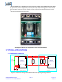
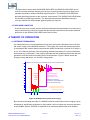
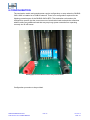
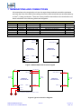
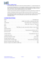
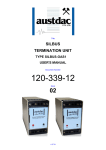
1
 FIN
NAL OPERAT
TION AND MA
AINTENANCE MANUAL – MINA MINIS
STRO HALES
S PROJECT
ORDEN DE COMPRA H336073-PM
M031/A 4501190525
FMC
C TECHNOLOGIES PROJJECT B6042
FMC Techn
nologies Chile LLtda. Callao #2970 Oficina 70
04 Edificio Studdio Las Condes Fono: 56‐2‐22
2320825 Title
SILBUS
TERMINATION UNIT
TYPE SILBUS-OAS1
USER'S MANUAL
Document Number
120-339-12
Issue
01
1 OF 10
REVISION CONTROL
02
01
Original
2010.01.18
PB’
PB’
JY
Issue
Details
Date
Written
Designed
Approved
Austdac Pty Ltd
Unit 1 / 4 Packard Avenue
Castle Hill NSW 2154
Australia
PO Box 6486
Baulkham Hills Business Centre
NSW 2153
Australia
Phone: + 61 2 8851 5000
Fax: + 61 2 9899 2490
Website: www.austdac.com.au
Austdac Inc.
455 Lowries Run Rd,
Pittsburgh, PA 15237
USA
Phone: +1 888 254 9155
Fax: +1 412 635 0179
Copyright 2010-01-18
This document remains the property of Austdac Pty. Ltd. It is subject to its recall and must not be
reproduced in part or whole or its contents divulged to third parties without prior written approval
from Austdac Pty Ltd.
SILBUS TERMINATION UNIT
TYPE SILBUS-OAS1 USER'S MANUAL
2 OF 10
120-339-12
Is s u e : 0 1
TABLE OF CONTENTS
REVISION CONTROL ...................................................................................................................... 2
TABLE OF CONTENTS.................................................................................................................... 3
PHOTOGRAPHS .............................................................................................................................. 3
TABLES ............................................................................................................................................ 3
FIGURES .......................................................................................................................................... 3
1 GENERAL DESCRIPTION ............................................................................................................ 4
2 FRONT PANEL LAYOUT .............................................................................................................. 4
3 TYPICAL APPLICATIONS............................................................................................................. 5
3.1 THREE-WIRE CONVEYOR.................................................................................................... 5
3.2 two-wire conveyor ................................................................................................................... 6
4 THEORY OF OPERATION............................................................................................................ 6
4.1 network termination................................................................................................................. 6
4.2 lightning protection.................................................................................................................. 7
5 OPERATING INSTRUCTIONS...................................................................................................... 7
6 CONFIGURATION......................................................................................................................... 8
7 TERMINATIONS AND CONNECTIONS........................................................................................ 9
7.1 EARTH CONNECTIONS ...................................................................................................... 10
8 SPECIFICATIONS ....................................................................................................................... 10
PHOTOGRAPHS
Photograph 1 SILBUS-OAS1-XXX front panel layout....................................................................... 4
Photograph 2 Access to configuration switch and potentiometer ..................................................... 5
Photograph 3 Termination switch and potentiometer ....................................................................... 8
TABLES
Table 1 Test facility connection details ............................................................................................. 7
Table 2 Termination unit connection details ..................................................................................... 9
FIGURES
Figure 1 Three-wire conveyor termination and control panel lightning protection ............................ 5
Figure 2 SILBUS Channel pulse with ringing.................................................................................... 6
Figure 3 SILBUS-OAS1-XXX terminal diagram ................................................................................ 9
Figure 4 Typical connection diagrams .............................................................................................. 9
SILBUS TERMINATION UNIT
TYPE SILBUS-OAS1 USER'S MANUAL
3 OF 10
120-339-12
Is s u e : 0 1
1 GENERAL DESCRIPTION
The SILBUS termination unit type SILBUS-OAS1-XXX is an explosion protected DIN railmounting module that is used to provide a SILBUS network termination, SILBUS test points
and head-end lightning protection. Typically a termination unit is required at both ends of a
SILBUS network or transmission line to help stop reflections and ringing in the SILBUS
waveform. The SILBUS-OAS1-XXX is produced in two versions, the SILBUS-OAS1-BEG
for the head-end and the SILBUS-OAS1-END for the tail-end of the SILBUS network.
The SILBUS-OAS1-BEG provides network termination, test facilities as well as lightning
protection for head-end control panels while the SILBUS-OAS1-END only provides network
termination and test facilities.
The termination unit is housed within a DIN rail mounting enclosure measuring 45mm (W) x
75mm (H) x 110mm (D). The front panel is located between the two top of enclosure
mounted terminal blocks to provide easy access to the two test points.
2 FRONT PANEL LAYOUT
The termination front panel is located between the terminal blocks that form part of the
enclosure. The front panel has two 2mm test points spaced at 19mm that provide test
access to the SILBUS signal and common signals. The front panel is shown in photograph
1 below.
Photograph 1 SILBUS-OAS1-XXX front panel layout
SILBUS TERMINATION UNIT
TYPE SILBUS-OAS1 USER'S MANUAL
4 OF 10
120-339-12
Is s u e : 0 1
The front panel can be snapped out and removed by using a wide bladed flat screw driver
to gain access to the configuration potentiometer and switch. Photograph 2 below shows
the front panel removed and the location of the configuration potentiometer and switch.
The two test sockets are also shown.
Photograph 2 Access to configuration switch and potentiometer
3 TYPICAL APPLICATIONS
3.1 THREE-WIRE CONVEYOR
1 SIGNAL
LANYARD
LANYARD 8
MONITOR
MONITOR 11
TO CHANNEL
GENERATOR
AND REMAINDER
OF PANEL
TERMINATION UNIT
TYPE SILBUS-OAS1-BEG
3 COMMON
SWITCH
TX
A?
11 SIGNAL (MONITOR)
EOL
TX
P7
EOL
TX
P8
TERMINATION UNIT
TYPE SILBUS-OAS1-END
COMMON
COMMON 14
14 COMMON
6 EARTH1
7 EARTH2
EARTH
EARTH
HEAD-END CONTROL PANEL
TAIL-END UNIT
Figure 1 Three-wire conveyor termination and control panel lightning protection
SILBUS TERMINATION UNIT
TYPE SILBUS-OAS1 USER'S MANUAL
5 OF 10
120-339-12
Is s u e : 0 1
The figure above shows how the SILBUS-OAS1-BEG and SILBUS-OAS1-END can be
used to correctly terminate a three wire conveyor control system to prevent ringing and
resultant interference with the SILBUS signal waveform. The SILBUS-OAS1-BEG also
provides lightning protection to the conveyor control panel. The SILBUS-OAS1-END does
not provide any lightning protection. The individual transmitters distributed along the
conveyor should also be protected against lightning if required.
3.2 TWO-WIRE CONVEYOR
A two wire conveyor control system would be terminated and protected in much the same
way as the three wire conveyor except that the lanyard conductor would not be used and
terminal 8 on the SILBUS-OAS1-BEG would not be used.
4 THEORY OF OPERATION
4.1 NETWORK TERMINATION
If a transmission line is not terminated correctly at its end points reflections can occur that
will cause ringing on the SILBUS waveform. This ringing can cause the channel generator
to misinterpret the channel pulse low period and falsely decide that a channel is on when it
is not. The channel generator uses a sampling method to determine if a channel has been
pulled down by a transmitter, if the ringing coincides with the sampling periods the channel
generator could be fooled into making an incorrect decision. Figure 2 below shows the
ringing crossing below the ‘on’ decision voltage point.
V
10
RINGING CAN CAUSE FALSE TRIGGERING OF PULSE WIDTH MODULATION
9
8
7
CORRECT
POSITION
OF
RISING
EDGE
6
5
4
FALSE TRIGGERED
OUTBOUND PULSE
WIDTH MODULATION
RINGING IS CAUSED BY
INCORRECT LINE TERMINATION
OR STUBS OR BRANCHES
3
2
RINGING CAN BE REDUCED
BY USING SILBUS-OAS1 OR BY
SAMPLING POINTS
ELIMINATING STUBS
1
uS
50 150 250
0uS 100 200
500
1000
Figure 2 SILBUS Channel pulse with ringing
By correctly terminating the ends of a SILBUS network transmission line the ringing can be
eliminated or significantly reduced to a point where it will not cause any incorrect operation
of the SILBUS system. SILBUS or Dupline® is an extremely reliable and noise tolerant
SILBUS TERMINATION UNIT
TYPE SILBUS-OAS1 USER'S MANUAL
6 OF 10
120-339-12
Is s u e : 0 1
system that is in most cases tolerant of unterminated networks, but some installations due
line length, branches and system architecture require line termination to function reliably.
Once the line termination has been fitted the system will operate correctly without further
effort on behalf of installation staff.
4.2 LIGHTNING PROTECTION
The SILBUS-OAS1-BEG provides lightning protection in the form of semiconductor
clamping and gas discharge tube clamping with diversion to earth. Further protection is
provided by common mode and differential inductive isolation.
A high speed semiconductor clamp between the signal and common lines will clamp any
differential lightning induced voltages to approximately 22 volts. This clamp is backed up
by a differential and common mode three terminal gas discharge device that shunts
lightning induced energy away to earth. Lightning induced energy is typically very high
frequency so inductive filters are used to isolate the control panel terminals of the
SILBUS-OAS1-BEG from high energy spikes. It is for this same high frequency that any
wiring from the earth terminals of the SILBUS-OAS1-BEG must be carried out in a low
inductive manner, failure to do so will render the SILBUS-OAS1-BEG ineffective in
reducing damage from lightning induced energy.
5 OPERATING INSTRUCTIONS
The termination unit does not require any operator action to operate once it has been
installed within an IP54 host enclosure and configured correctly.
Test connection facilities are provided on the front panel of the termination unit to provide a
method of connecting test equipment to the network while the system is in operation. Care
should be exercised when using these test facilities to not short the SILBUS network and
cause tripping of conveyor drive motors and similar plant.
TERMINATION UNIT TEST FACILITY CONNECTIONS
FRONT PANEL NAME
COLOUR
NETWORK SIGNAL
SIG
RED
SIGNAL
COM
BLACK
COMMON
Table 1 Test facility connection details
TERMINAL No.
11
14
The test facilities are in the form of two 2mm test sockets spaced at 19mm. These test
sockets will accept standard multimeter probes and leads.
SILBUS TERMINATION UNIT
TYPE SILBUS-OAS1 USER'S MANUAL
7 OF 10
120-339-12
Is s u e : 0 1
6 CONFIGURATION
The termination switch and potentiometer require configuration or setup when the SILBUSOAS1-XXX is installed on a SILBUS network. There is no configuration required for the
lightning protection part of the SILBUS-OAS1-BEG. The termination unit needs to be
configured to provide just the correct amount of termination load to absorb the reflections
without adding any additional load that may stop long system networks from operating
correctly due to IxR losses.
Photograph 3 Termination switch and potentiometer
Configuration procedure to be provided.
SILBUS TERMINATION UNIT
TYPE SILBUS-OAS1 USER'S MANUAL
8 OF 10
120-339-12
Is s u e : 0 1
7 TERMINATIONS AND CONNECTIONS
All connections to the termination unit are via cage-clamp terminals around the perimeter
and near the front of the DIN rail mounting enclosure, these terminals can accommodate up
to 4mm2 (11awg) conductors. There are seven possible connections to the termination unit;
these are shown in the following tables and diagrams:
TERMINAL #
1
3
6
7
8
11
14
NAME
SIGNAL
COMMON
EARTH
EARTH
LANYARD
MONITOR
COMMON
TERMINATION UNIT CONNECTION DETAILS
WIRE COLOUR
FUNCTION
RED
SILBUS SIGNAL CONTROL PANEL
BLACK
SILBUS COMMON CONTROL PANEL
GREEN/YELLOW
PROTECTIVE EARTH
GREEN/YELLOW
PROTECTIVE EARTH
YELLOW
RED
BLACK
-BEG / -END
-BEG
-BEG
-BEG
-BEG
-BEG1
-BEG -END
-BEG -END
NOTE 1 - FITTED TO SILBUS-OAS1-END BUT NOT USED IN TAIL END APPLICATIONS
Table 2 Termination unit connection details
1 SIGNAL
LANYARD 8
SIGNAL (MONITOR) 11
MONITOR 11
TERMINATION UNIT
TYPE SILBUS-OAS1-BEG
3 COMMON
TERMINATION UNIT
TYPE SILBUS-OAS1-END
COMMON 14
COMMON 14
6 EARTH1
7 EARTH2
Figure 3 SILBUS-OAS1-XXX terminal diagram
SIG
1 SIGNAL
LANYARD 8
MONITOR 11
TO CHANNEL
GENERATOR
LANYARD (NOTE1)
MONITOR (SIGNAL)
TO FIELD
NETWORK
TERMINATION UNIT
TYPE SILBUS-OAS1-BEG
COM
3 COMMON
COMMON 14
SIGNAL (MONITOR) 11
SIGNAL
FROM FIELD
NETWORK
TERMINATION UNIT
TYPE SILBUS-OAS1-END
COMMON
COMMON 14
COMMON
6 EARTH1
7 EARTH2
NOTE 1 LANYARD ONLY REQUIRED IN THREE WIRE SYSTEMS
EARTH
EARTH
Figure 4 Typical connection diagrams
SILBUS TERMINATION UNIT
TYPE SILBUS-OAS1 USER'S MANUAL
9 OF 10
120-339-12
Is s u e : 0 1
7.1 EARTH CONNECTIONS
The SILBUS-OAS1-BEG has two earth connection terminals (6, 7), these terminals must
be connected independently to a low impedance lightning earth point using a minimum of
4mm2 conductors. These conductors shall be as short as possible and twists and bends
should be avoided if proper lightning protection is to be afforded.
The two earth conductors should be segregated from all other panel wiring to reduce any
induction of lightning derived energy into signal conductors within the control panel.
If the lightning earth point is far away from the control panel then an earth stud or terminal
shall be provided on the control panel gear tray to allow the earth conductors to be
increased to 8mm2.
8 SPECIFICATIONS
Name ............................................................................................................... Termination unit
Type ...................................................................SILBUS-OAS1-BEG and SILBUS-OAS1-END
Terminations .................................................................. Cage clamp 4mm2 (11awg) maximum
Size .................................................................................. 45mm (W) x 75mm (H) x 110mm (D)
Mass .................................................................................................................................. 145g
Fixing ..........................................TS35 DIN rail or screw mount M4 on 85mm x 61mm centres
Ingress protection ............................................................................................................... IP20
Enclosure material ............................................................. Polycarbonate (30%GV) UL 94 V-1
Enclosure colour ................................................................................................RAL 7032 Grey
Terminal material ............................................................................... Polycarbonate UL 94 V-2
Terminal block colour........................................................................................................ Black
Operating temperature range.................................................................................. 0ºC to 40ºC
Storage temperature range.................................................................................. -20ºC to 80ºC
Operating relative humidity range ................................................ 10% to 90% Non condensing
Maximum clamping voltage (-BEG only).............................................................................. 22V
Maximum impulse current 8/20uS (-BEG only).................................................................... 5kA
SILBUS TERMINATION UNIT
TYPE SILBUS-OAS1 USER'S MANUAL
10 OF 10
120-339-12
Is s u e : 0 1