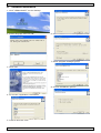
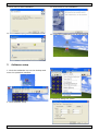
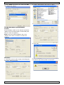
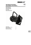
1
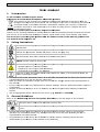
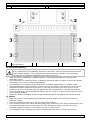
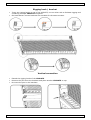
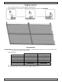
V VDPLA AT5 FU ULL COLO OR LED SCREEN S P25 - SM MD LED - 1600x8 800mm US SER MANUAL 2 VDPLAT5 5 Use er man nual 1.. Introd duction To o all reside ents of the e European Union Im mportant environme e ental inforrmation ab bout this product p This symbol on the device e or the pac ckage indica ates that disposal of tthe device after a its lifecy ycle could harm h the environmentt. Do not dispose of th he unit (or batteries) as unsorted d municipal waste e; it should d be taken to t a specialized company for rec cycling. This s device uld be returrned to you ur distributo or or to a lo ocal recyclin ng service. Respect th he local shou envirronmental rules. If in doubt, contact yo our local waste w disp posal auth horities. Th hank you fo or choosing HQPower™ ™! Please re ead the ma anual thorou ughly beforre bringing this device e intto service. If the devic ce was dam maged in tra ansit, don'tt install or use u it and c contact you ur dealer. Fo or more info concern ning this product p an nd the late est version n of this m manual, ple ease visit ou ur website e www.hqp power.eu. 2.. Safety y Instruc ctions Be very carefu ul during th he installation: touchin ng live wire es can cause life-threa atening elec ctroshocks.. Alw ways disconnect mains s power when device not n in use or o when serrvicing or maintenanc m ce actiivities are performed. p e power cord by the plug p only. Handle the Kee ep this deviice away fro om children n and unau uthorized us sers. Cau ution: deviice heats up during us se. Do not stare directly at a the lightt source, as a this may y cause - epileptic se eizure in se ensitive peo ople b - temporarily loss of sight (flash blindness) ble) eye da amage - permanentt (irreversib The ere are no user-servic u eable parts s inside the e device. Re efer to an a authorized dealer d for serv vice and/orr spare partts. • This device e falls unde er protectio on class I. It I is therefo ore essentia al that the device be earthed. e Ha ave a qualified d person carry out the electric co onnection. e that the available voltage does not exceed d the voltag ge stated in n the speciffications of • Make sure this manua al. • Do not crim mp the pow wer cord an nd protect it against damage. Have an auth horised dealer replace it if necessarry. • Respect a minimum distance d off 0.5 m betw ween the device’s d ligh ht output an nd any illum minated surface. • Use an appropriate safety cable e to fix the device (e.g g. VDLSC7 or VDLSC8 8). 3.. Generral Guide elines Re efer to the Velleman® V ® Service and Quality Warran nty on the last pages of this man nual. Keep this device awa ay from dus st and extreme heat. Protect this device frrom shocks s and abuse e. Avoid bru ute force when operatting the device. • Familiarise e yourself with w the fun nctions of the device before b actually using it. Do not allow a operation by unqualiffied people. Any dama age that may occur will most pro obably be due d to e. unprofessiional use off the device • All modific cations of th he device are a forbidde en for safetty reasons. Damage caused by user u modificatio ons to the device d is no ot covered by the warrranty. 19//05/2011 2 ©Velleman n nv VDPLAT5 • Only use the device for its intended purpose. All other uses may lead to short circuits, burns, electroshocks, lamp explosion, crash, etc. Using the device in an unauthorised way will void the warranty. • Damage caused by disregard of certain guidelines in this manual is not covered by the warranty and the dealer will not accept responsibility for any ensuing defects or problems. • A qualified technician should install and service this device. • Do not switch the device on immediately after it has been exposed to changes in temperature. Protect the device against damage by leaving it switched off until it has reached room temperature. • This device is designed for professional use on stage, in discos, theatres, etc. The VDPAT5 must be used with an alternating current of 230 VAC~50 Hz. • Lighting effects are not designed for permanent operation: regular operation breaks will prolong their lives. • Use the original packaging if the device is to be transported. • Keep this manual for future reference. 4. Features • full-colour screen with SMD LEDs for stage and other applications such as special events, advertising... • lightweight aluminium alloy frame, super-thin design • easy to install, even without tools • for indoor and outdoor use (IP54) • accessories (not incl.) flightcase for 4 x VDPLAT5: VDPLAT5/FC hardware: VDPLAT5/H rigging module: VDPLAT5/RM spare LED strip (71cm in-between 2 screws): VDPLAT5/SP1 spare LED strip (55cm in-between 2 screws): VDPLAT5/SP1-2 5. Hardware installation 1 19/05/2011 VDPLAT5 2 3 Power cable (0.4m, max. 16A) ©Velleman nv VDPLAT5 3 1 Signal cable (0,4m, Ethernet) Power/signal OUTPUT (and test button) 2 3 Power/signal INPUT Rigging coupling 3 Rigging plate a) Overhead mounting Risk of injury. Overhead mounting requires extensive experience: calculating workload limits, determining the installation material to be used… Have the material and the device itself checked regularly. Do not attempt to install the device yourself if you lack these qualifications as improper installation may result in injuries. • Have the device installed by a qualified person, respecting EN 60598-2-17 and all other applicable norms. • The construction to which the device is attached should be able to support 10 times the weight of the device for one hour without deformation. • The installation must always be secured with a secondary attachment e.g. a safety cable. • Never stand directly below the device when it is being mounted, removed or serviced. Have a qualified technician check the device once a year and once before you bring it into service. • Install the device in a location with few passers-by and inaccessible to unauthorised persons. • For truss-mounting, use an appropriate clamp (not incl.) and fit an M10 bolt through the centre of the (folded) bracket. • Adjust the desired inclination angle via the mounting bracket and tighten the bracket screws. b) general • Make sure there is no flammable material within a 50cm radius of the device and there is sufficient cooling. • Have a qualified electrician carry out the electrical connection. • Connect the device to the mains with the power plug. All fixtures must be powered directly off a grounded switched circuit and cannot be run off a rheostat or dimmer circuit, even if the rheostat or dimmer channel is used solely for 0% to 100% switch. • The installation has to be approved by an expert before the device is taken into service. 19/05/2011 4 ©Velleman nv VDPLAT5 Rigging hook / bracket • • There are rigging hooks on top of the VDPLAT5, one on either side to facilitate rigging and combining multiple VDPLAT5’s together. On both bottom corners brackets are provided for the same purpose. Vertical connection • • • Extend the rigging hooks of the VDPLAT5. Remove the pins from the brackets and place another VDPLAT5 on top. Re-insert the pins in the brackets. 19/05/2011 5 ©Velleman nv VDPLAT5 Horizontal connection • • On the left of each frame of the VDPLAT5 there are 2 nuts; on the right there are two Allen screws. Place two VDPLAT’s side by side and turn the Allen screws to connect them together. 19/05/2011 6 ©Velleman nv VDPLAT5 Rigging coupling • • Fix the clamp (not incl.) on the rigging coupling first. Use the bolt to fix the rigging coupling to the rigging hooks of the VDPLAT5. Connections ATTENTION: do not connect more than 4 panels to a single power input; do not connect more than 20 panels via a single signal cable. RJ45 connector: T568A T568B 1 White/green White/orange 2 Green Orange 3 White/orange White/green 4 Blue Blue 5 White/blue White/blue 6 Orange Green 7 White/brown White/brown 8 Brown Brown It is recommended to use the T568B configuration. Use a straight cable to link VDPLAT5’s together and to a PC.. 19/05/2011 7 ©Velleman nv VDPLAT5 6. Software installation 1. Click “LEDStudio937” on the desktop 2. Select language and click OK. 6. Choose destination directory. 7. Select program manager group 3. Click next 8. Choose installation options. 4. Fill out the registration information 5. Confirm and click next. 19/05/2011 8 ©Velleman nv VDPLAT5 9. Click next to start installation 11. Click finish to exit installation. 10. Installation in progress: 12. Locate the LedStudio8 icon on the desktop. 7. Software setup 1. Click the LedStudio icon on the desktop and enter the operation interface. 3. Following dialog box opens: 2. Click Software setup. 19/05/2011 9 ©Velleman nv VDPLAT5 4. Enter linsn followed by the password 168. The dialog box opens: 2. Locate ‘ALPHA.RCG’ and click on ‘open’. 3. Click on ‘send to receiver’. Setup hardware parameters Sender: set the display mode to the desired resolution (default and recommended is 1024x768) and click on ‘save on sender’). Note: when the LEDs suddenly dim, click ‘default’ and ‘save on sender’ to solve the problem. 4. Click ‘OK’. Receiver: 1. Click the receiver tab to open the dialog box and click ‘load from files’. 19/05/2011 5. Click to save the data on the receiving card. If not, data is lost when power is removed. 10 ©Velleman nv VDPLAT5 6. Check all settings and click on ‘save on receiver’. 8. Make sure all parameters are correct and click ‘Yes’. 7. Click ‘OK’. Display connection Open the tab ‘Display connection’ to enter the setup interface. 1. input number of displays, 2. Click ‘update display QTY’ 3. Setup the screen type, e.g. full colour, double colour... 4. Input the number of cards, X (horizontal cards), Y (vertical cards). The connection scheme is shown on the screen. 5. Click ‘Gama’ and enter 2.8. 6. Setup Red – Green – Blue brightness (recommended value: 255). 7. Click on the top left module 19/05/2011 8. Mail cable: max. 4 sending cards can be cascaded; each sending card has 2 signal output ports, so 8 options are available. 9. Extension cable: Ethernet cable core 1-8 (signal out). If multiple cables are used, the second cable starts with signal output port 9, the third cable with 17 and so on. 10. Width and height are those of the panel. 11. Order No.: signal cable number that is connected to the panel. Example: Main cable: No. 1 Extension cable: 1 Order No.: 1 Width: 64 Height: 32 11 ©Velleman nv VDPLAT5 12. Click ‘save to receiver’. Check whether the screen works correctly and click ‘Yes’. Following screen is shown: 8. Troubleshooting Problem Possible cause All LED panels are not working No video input No signal No power No signal Fault on LED panel All LED are flashing Connection or signal problem Defective receiving card 19/05/2011 Possible solution If red indicator LED on the CNT is off, check power input. If green LED on CNT is not flashing, check DVI input. If DVI input is OK, the problem is located in the main power or processor board of the CNT. If green LED on CNT flashes, check Ethernet connection (cable not broken, length within limits). Check red LED on hub or first LED panel connected to the CNT. If this is off than a power supply problem is present. If the green LED on the LED panel is not flashing, a problem could be in the Ethernet cable, power supply or processor board of the panel. Replace the suspected with a good one. If problem is solved, the suspected panel is broken. Contact your local dealer. Check Ethernet cables and connections. Check power supply. The green LEDs on the LED panels and CNT must flicker regularly. If not, check the CNT for defects: check DVI input, power supply and processor board. Replace the suspected panel with a good one. If problem is solved, the suspected panel is broken. Contact your local dealer. 12 ©Velleman nv VDPLAT5 9. Cleaning and maintenance • This unit does not need regular maintenance. • All screws should be tight and free of corrosion. • The housing, the lenses, the mounting supports and the installation location (e.g. ceiling, suspension, trussing) should not be deformed, modified or tampered with e.g. do not drill extra holes in mounting supports, do not change the location of the connections … • Mechanically moving parts must not show any signs of wear and tear. • The electric power supply cables must not show any damage. Have a qualified technician maintain the device. • Regularly remove dust from the housing and the air vents using a slightly damp cloth. • There are no user-serviceable parts inside. Refer to an authorized dealer for service and/or spare parts. 10. Technical Specifications power supply power consumption 230VAC/50Hz average 500W peak 700W pixel configuration 1x RGB full-colour SMD LED pixels/unit 32 x 46 pixel pitch 25mm pixel density 1600 pixels/m² luminance 2000 cd/m² scanning mode static frame change 60 frames/sec control distance < 100m (no delay) control mode in step with computer monitor display mode 1024x768 or 800x600 viewing distance 30 ~ 100m viewing angle 120° (horizontal/vertical) greyscale 256 levels display colours 16777216 colour temperature 6500 ~ 9500K blind pixel rate 0.0002 IP rate IP52 dimensions 1600 x 800 x 140mm weight 21.5kg Use this device with original accessories only. Velleman nv cannot be held responsible in the event of damage or injury resulted from (incorrect) use of this device. For more info concerning this product and the latest version of this manual, please visit our website www.hqpower.eu. The information in this manual is subject to change without prior notice. © COPYRIGHT NOTICE The copyright to this manual is owned by Velleman nv. All worldwide rights reserved. No part of this manual or may be copied, reproduced, translated or reduced to any electronic medium or otherwise without the prior written consent of the copyright holder. 19/05/2011 13 ©Velleman nv VDPLAT5 Velleman® Service and Quality Warranty Velleman® has over 35 years of experience in the electronics world and distributes its products in more than 85 countries. All our products fulfil strict quality requirements and legal stipulations in the EU. In order to ensure the quality, our products regularly go through an extra quality check, both by an internal quality department and by specialized external organisations. If, all precautionary measures notwithstanding, problems should occur, please make appeal to our warranty (see guarantee conditions). General Warranty Conditions Concerning Consumer Products (for EU): • All consumer products are subject to a 24-month warranty on production flaws and defective material as from the original date of purchase. • Velleman® can decide to replace an article with an equivalent article, or to refund the retail value totally or partially when the complaint is valid and a free repair or replacement of the article is impossible, or if the expenses are out of proportion. You will be delivered a replacing article or a refund at the value of 100% of the purchase price in case of a flaw occurred in the first year after the date of purchase and delivery, or a replacing article at 50% of the purchase price or a refund at the value of 50% of the retail value in case of a flaw occurred in the second year after the date of purchase and delivery. • Not covered by warranty: - all direct or indirect damage caused after delivery to the article (e.g. by oxidation, shocks, falls, dust, dirt, humidity...), and by the article, as well as its contents (e.g. data loss), compensation for loss of profits; - frequently replaced consumable goods, parts or accessories such as batteries, lamps, rubber parts, drive belts... (unlimited list); - flaws resulting from fire, water damage, lightning, accident, natural disaster, etc. …; - flaws caused deliberately, negligently or resulting from improper handling, negligent maintenance, abusive use or use contrary to the manufacturer’s instructions; - damage caused by a commercial, professional or collective use of the article (the warranty validity will be reduced to six (6) months when the article is used professionally); - damage resulting from an inappropriate packing and shipping of the article; - all damage caused by modification, repair or alteration performed by a third party without written permission by Velleman®. • Articles to be repaired must be delivered to your Velleman® dealer, solidly packed (preferably in the original packaging), and be completed with the original receipt of purchase and a clear flaw description. • Hint: In order to save on cost and time, please reread the manual and check if the flaw is caused by obvious causes prior to presenting the article for repair. Note that returning a non-defective article can also involve handling costs. • Repairs occurring after warranty expiration are subject to shipping costs. • The above conditions are without prejudice to all commercial warranties. The above enumeration is subject to modification according to the article (see article’s manual). 19/05/2011 14 ©Velleman nv