1
OPERATION MANUAL
MODEL 506A
B. Status Sets (from Instrument to Remote)
B.1 Condition:
Case: PC queries the all of logger counters from meter.
Ex. PC send “$001G/r”, then meter response “!001G005150000200000/r”
Means:
Here meter ID: 001
Save counter: 515
Log Group counter: 2
ALM logger counter: 0
/r Î <CR> <LF> (Hex, 0D, 0A).
B.2 Condition:
Case: PC queries the LOG data in GROUP 6th of meter ID 001.
Ex. PC send “#001L00006/r”, then meter response
“>001L0000111554170704111220420900115000001/r”
PC sends “#001D00006/r”, then meter will dump all of data of group 6th.
“> 001D00006/rxxxxxx/rxxxxxx/rxxxxxx/r……………”
Means:
>001L: meter response, Here meter ID: 001
Scale: degree C
Logging Mode: 1 (logging T1 input)
T1_type: K type
T2_type: K type
Decimal Point: 1
ChA_type: ohm
ChB_type: User define, %RH
Time: year: 2004; month: 11; day: 12; hour: 20; minute: 42; second:09
Logger counts: 115
Interval: 1 second
xxxxxx: Value
/r Î <CR> <LF> (Hex, 0D, 0A).
Ver. 2
23
01/07/08
Alarm Log Data(AD)
mode=1,mode=2
Alarm Log Data(AD)
mode=3
Alarm Log Data(AD)
mode=4
Battery Voltage(VB)
7+
30*n
7+
32*n
7+
39*n
6
S
S
S
S
GroupID (/r) c/f mode T1_type T2_type
AC Time Value
5+2
1
1
1
1
5
12
6
H/L ST/SP
1
2
GroupID (/r) c/f mode dp cha_type
AC Time Value
5+2
1
1
1
1
5
12
6
H/L ST/SP /r
1
2
2
GroupID (/r) c/f mode dp chb_type
chb_text AC Time
5+2
1
1
1
2
6
5
12
Value H/L ST/SP /r
6
1
2
2
00 . 00 V
2
1 2
1
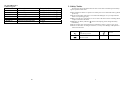
Note:
1. Communication Protocol : 9600, 8, E, 2.
2. /r Î <CR> <LF> (Hex, 0D, 0A).
22
TABLE OF CONTENTS
ˇ
ˇ
ˇ
ˇ
PAGE
1. Safety Notice.............................................................................................................................1
2. Specifications............................................................................................................................2
2.1 Electronic Specifications........................................................................................................2
2.2 Accuracy .................................................................................................................................2
3. Names of Outer Parts ..............................................................................................................3
4. Battery Installation ..................................................................................................................6
5. Turn On and Off Model 506A .................................................................................................7
6. Check Battery Voltage .............................................................................................................7
7. Measurement and Main Function of Buttons ........................................................................7
7.1 MIN/MAX Button..................................................................................................................8
7.2 HOLD Button.........................................................................................................................8
7.3 Hi/Lo Button...........................................................................................................................8
7.4 RELΔ Button ..........................................................................................................................8
Button ..............................................................................................................................8
7.5
7.6 LOG Button............................................................................................................................8
7.7 SAVE Button...........................................................................................................................9
7.8 ALM LOG Button..................................................................................................................9
8. Measurement and Main Function of Buttons ........................................................................9
8.1 D1-Setting the Main Display .................................................................................................9
8.2 D2-Setting Second Display ..................................................................................................10
8.3 D3-Setting Third Display.....................................................................................................10
8.4 T1 TYPE and T2 TYPE-Setting the Types of Thermocouple for T1 or T2 .....................10
8.5 T1 ADJ and T2 ADJ-Setting the Off-Set Adjustment for T1 or T2..................................10
8.6 CHA TYPE-Setting the Types of RTD for CHA................................................................ 11
8.7 CHA ADJ-Setting the Off-Set Adjustment for RTD.......................................................... 11
8.8 CHA RNGE-Setting the Resolution for Channel A (CHA)............................................... 11
8.9 CHB TYPE-Setting the Unit for Channel B ......................................................................12
8.10 CHB PARA-Create Special Unit for Channel B (CHB)..................................................12
8.11 CHB RNGE-Select the Resolution for Channel B (CHB) ...............................................13
8.12 MEN VIEW CLR-Setting..................................................................................................13
8.13 °C/°F Selecting Temperature Unit (°C/°F) .......................................................................16
8.14 REL-Setting Reference Value for Relative Reading........................................................16
8.15 Hi/Lo-Setting High and Low Limits for Alarm and Alarm Log.....................................16
-Setting Time Length of Backlight ..............................................................................16
8.16
8.17 APO-Auto Power Off Time Setting...................................................................................17
8.18 INVT-Set Time interval of data logging ...........................................................................17
8.19 PERIOD-Set length of Time of data logging....................................................................18
8.20 TIME-Time Setting............................................................................................................18
8.21 DATE-Date Setting ............................................................................................................18
9. Maintenance ...........................................................................................................................18
A. Command Sets (from Remote to Instrument) ...................................................................19
B. Status Sets (from Instrument to Remote) ..........................................................................23
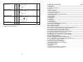
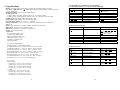
2. Data Format Definition
Len
Type Description
Rd Wr
Byte
ˇ ˇ
ID Number (ID)
3
S 1 ~ 999 (ASCII)
ˇ ˇ
Description (DE)
40
S
YYMMDDHHMMSS
ˇ ˇ
Time (TI)
12
S
GroupID hour minute second
/r
ˇ ˇ
Time_INV set
19
S
5
4
4
4
2
GroupID T1_data T1_type T2_data T2_type
c/f cha_data
5
6
1
6
1
1
7
ˇ
DATA OUT (#IDN)
47
S
chat_ype chb_data chb_type chb_text
cha/chb
/r
1
7
2
6
2
2
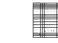
Counts
ˇ
Saved Data Counter (SC)
5
S
5
Counts
ˇ
Log Data Counter (LC)
5
S
5
Counts
ˇ
Alarm Counter (AC)
5
S
5
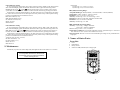
GroupID SC c/f mode T1_type
Saved Data (SD)
T2_type Time Value /r
ˇ
34
S
mode=1, mode=2
5
5
1
1
1
1
12
6
2
GroupID SC c/f dp cha_type Time
Saved Data (SD)
Value /r
ˇ
34
S
mode=3
5
5
1
1
1
2
6
2
GroupID SC c/f dp chb_type
Saved Data (SD)
chb_text Time Value /r
ˇ
41
S
mode=4
5
5
1
1
2
6
12
6
2
GroupID c/f mode T1_type T2_type
dp cha_type
5
1
1
1
1
1
1
ˇ
Log Status (LS)
43
S
LC
chb_type chb_text
TI
TSEC /r
2
6
12
5
6
2
Log Data (LD)
GroupID( /r) D1 /r D2 /r … Dn /r
ˇ
7+ 8*n S
n = recorded channel x LC
5+2
6
2
6
2 …
6 2
Sampling Time (TSEC)
6
S HHMMSS
Name
Alarm
(LMS)
Limit
Counts
12
S
Hi-Limit
6
21
Lo-limit
6
ˇ
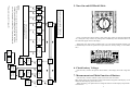
A4. Quick Reference
1. 506A-Program
Mode:
MODE=1
MODE=2
MODE=3
MODE=4
MODE=5
MODE=6
MODE=7
1. Safety Notice
Channel:
Record T1
Record T2
Record CHA
Record CHB
Record T1and T2
Record T1,T2 and CHA
Record T1,T2 and CHB
Record mode
SAVE,ALARM and Logger
SAVE,ALARM and Logger
SAVE,ALARM and Logger
SAVE,ALARM and Logger
Logger
Logger
Logger
The following safety information must be observed to ensure maximum personal safety during the operation at this meter:
z This instrument contains no operator serviceable part. Service should be done by qualified
person only.
z Do not use the meter if the meter or test leads look damaged, or if you suspect that the
meter is not operating properly.
z Before open the case of the meter, be sure to remove all the accessories including thermocouples connected to the meter.
z When the low battery indicator ( ) shown in the display, please change the battery
immediately.
z Do not use this meter in the dangerous circumstances (such as: explosive gas, vapor).
z Please use this meter according to instruction, or it may cause damage of the protective
function of the meter.
AC
Alternating Current
Ground
DC
Direct Current
20
1
2. Specifications
Display: 4 1/2 digit liquid crystal display (LCD) with a maximum reading of 19999.
Low Battery Indication: The “ ” displayed and blinking when the battery voltage drops below
the operating level.
Measurement Rate: 2.5 times per second (nominal).
Continuous Record:
1. Single channel recording: 32000 records (T1 or T2 or CHA or CHB).
2. Multi channel recording: 6500 records (T1+T2 or T1+T2+CHA or T1+T2+CHB).
ALM Record: 5400 samples with start/stop time. (Max.)
Single Record: 6500 samples with real-time data. (Max.)
Operating Environment: 0°C to 50°C at < 70% R.H.
Storage Temperature: -20°C to 60°C, 0 to 80% R.H. with battery removed from meter.
Safety: CE
Power: Single standard 9-volt battery (NEDA 1604, JIS 006P, IEC 6F22).
Battery Life: 100 hours typical with carbon-zinc.
Dimensions: 192mm (H) x 91mm (W) x 52.5mm (D).
Weight: 435g including battery.
Accessories:
K-type thermocouples (2 pcs)
Co-axial cable (RTD) (1pcs)
RS232 transmission cable (1pcs)
CD-ROM (software) (1pcs)
9V battery (installed) (1pcs)
Operating manual
2.1 Electronic Specifications:
Thermocouple(T1、T2)Measuring Range:
K-TYPE (Resolution 0.1°): -200°C to 1372°C, -328°F to 2501°F
J-TYPE (Resolution 0.1°): -210°C to 1200°C, -346°F to 2192°F
T-TYPE (Resolution 0.1°): -200°C to 400°C, -328°F to 752°F
E-TYPE (Resolution 0.1°): -210°C to 1000°C, -346°F to 1832°F
R-TYPE (Resolution 1°): 0°C to 1767°C, 32°F to 3212°F
S-TYPE (Resolution 1°): 0°C to 1767°C, 32°F to 3212°F
N-TYPE (Resolution 0.1°): -50°C to 1300°C, -58°F to 2372°F
Resolution: 0.1°C /1°C, 0.1°F /1°F (Auto Ranging)
2.2 Accuracy:
K/J/T/E TYPE
±(0.05% rdg + 0.3°C) on -50°C to 1370°C
±(0.05% rdg + 0.7°C) on -50°C to -210°C
±(0.05% rdg + 0.6°F) on -58°F to 2501°F
±(0.05% rdg + 1.4°F) on -58°F to -346°F
N -TYPE
±(0.05% rdg + 0.8°C) on -50°C to 0°C
±(0.05% rdg + 0.4°C) on 0°C to 1300°C
±(0.05% rdg + 1.6°F) on -58°F to 32°F
±(0.05% rdg + 0.8°F) on 32°F to 2372°F
2
A. Command Sets (from Remote to Instrument)
A. 1 Instrument Setup (%) , only use for broadcasting
Command Syntax
Command Name
%ID I ID
New ID
%000 R
%ID D DE
%ID T TI
%ID L LM
%ID S TSEC
%ID M
Read ID
Setup description
Timer setup
Limit setting
Log sampling time
Clean Memory
Description
ID: original ID
ID: New ID
DE: Descriptive Text
TI: timer count
LM: Hi/Lo limit and Range
TSEC: Log sampling time
Unknown or Error EchoÎ?
A.2 Instrument Status ($)
Command Syntax
Command Name
$ID G
Read group counter
$ID D
$ID T
$ID L
$ID S
$ID B
Read description
Read Timer
Read Limits Value
Read Sampling Time
Read Battery Voltage
Description
Echo: ! ID G SC , LC , AC
SC: saved group count
LC: log group count
AC: alarm count
Echo: ! ID D DE
Echo: ! ID T TI
Echo: ! ID L LMS
Echo: ! ID S TSEC
Echo: ! ID B VB
Unknown or Error Echo Î?
A.3 Measurement (#)
#ID N
Command Name
Read current data
#ID S [SC]
Read saved data
#ID L [LC]
#ID D [LC]
#ID G [Start] , [Stop]
5 1 5
#ID B
Read log status
Read log data
Read saved data group
Command Syntax
Read alarm log data
Description
Echo: > ID N #IDN
#IDN: Current Data
Echo: > ID S SD
SD: Saved Data
Echo: > ID L LS
Echo: > ID D LD
Echo: > ID G SDG
Echo: > ID B AD
AD: Alarm Log Data
Unknown or Error EchoÎ?
19
8.20 TIME-Time Setting
To set or change the system time. Place rotary switch at position “TIME” mode. The time and
date on the third display panel should blink. Enter from left to right in the following format
HH:MM:SS. Press On ( ), under ( ) button printed on the overlay in white word to set the
system date. Press the “ENTER” button to confirm. Exit this function by pressing ESC button.
Except these 2 positions mentioned above, all other position are for system setting, the indicator “SET” shows at left side of LCD when place the rotary switch at any of these system setting
positions. And 2nd functions of buttons are active.
HH: Interval Hour (0~23)
MM: Interval Minute (0~59)
SS: Interval Second (0~59)
MAX: 23:59:59
MIN:00:00:01
8.21 DATE-Date Setting
To set or change the system data. Place rotary switch at position “Date” mode. The time and
date on the third display panel should blink. Enter from left to right in the following format YY:
MM: DD. Press On ( ), under ( ) button printed on the overlay in white word to set the system date. Press the “ENTER” button to confirm. Exit this function by pressing ESC button.
Except these 2 positions mentioned above, all other position are for system setting, the indicator “SET” shows at left side of LCD when place the rotary switch at any of these system setting
positions. And 2nd functions of buttons are active.
Y: Interval year (20 "00" ~20 "99")
M: Interval month (1~12)
D: Interval date (1~31)
MAX: 99:12:31
MIN: 00:01:01
9. Maintenance
R/S-TYPE
±(0.05% rdg + 2°C) on 0°C to 1767°C
±(0.05% rdg + 4°F) on 32°F to 3212°F
CHA (RTD) Measuring Range:
Acceptable RTD Type: Pt385(100ohm)、Pt3916(100ohm)、Pt3926(100ohm).
Temperature: -200°C to 800°C, -328°F to 1472°F
Resolution: 0.01, 0.1 for above ±200 °C/°F.
Accuracy: ±0.05% rdg + 0.2°C or ±0.05% rdg + 0.4°F
Resistance: 0 ohm to 199.99 ohm, 200.0 ohm to 400.0 ohm.
Resolution: 0.01, 0.1 for above 200 ohm.
Accuracy: ±0.05% rdg + 0.1 ohm.
CHB (ADAPTER) Measuring Range:
Accuracy: ±(0.1% rdg + 10dgts) on 200mV
±(0.5% rdg + 4°dgts) on 2000mV
Stated accuracy at 23°C ± 5°C, <75% R.H.
Temperature Coefficient: 0.1 times the applicable accuracy specification per °C from 0°C to
18°C and 28°C to 50°C (32°F to 64°F and 82°F to 122°F).
Input Protection: 24V DC or 24V AC rms maximum input voltage on any combination of
input pins.
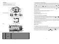
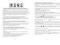
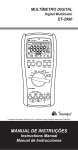
3. Names of Outer Parts:
Front Side:
1.
2.
3.
4.
LCD.
Push buttons.
Rotary switch.
Socket of CHB (channel B) for voltage input.
Periodically wipe the case with a damp cloth, detergent and do not use abrasives or solvents.
WARNING:
To avoid possible electrical shock, disconnect the
thermocouple connectors from the thermometer
before removing the cover.
18
3
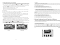
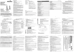
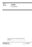
Top Side:
1.
2.
3.
4.
Socket of power (DC 12V, more then 100mA).
RS232 (Optical Interfaced) port.
Socket of CHA (channel A) for RTD input.
Sockets of K type thermocouples T1 and T2.
4
3
1
2
Connection Of RTD
Configuration of Mini-Din Connector
Wire connection to RTD
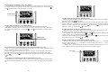
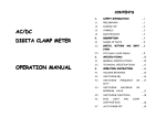
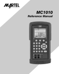
LCD:
8.17 APO-Auto Power Off Time Setting
Use this function to change the time for the auto power off (APO) function. Place rotary
switch at position “INVT”, and the indicator “APO” and the main display will blink on the LCD,
and the previous setting will be displayed. The default time for APO is 1 minute. Press On ( ),
under ( ) button printed on the overlay in white word to set the APO time. On ( ), under ( )
direction key: Time value, right ( ), left ( ) direction key: Time figure. Press “CANCEL” button
to back to previous setting. Confirm selection and exit setting mode by pressing “confirm ( )”
button. Press “ESC” button to abort change and exit the setting mode with previous setting remains unchanged. Confirm selection and exit setting mode by pressing “confirm ( )” button.
MAX: 9998 minutes
MIN: 0001 minutes
Disable APO function: To set the time at 9999 will disable APO function.
APO Function will be Disabled also in Follow situation:
External power is used.
RS-232 function is used.
MAX, MIN, MAX-MIN, AVG function is used.
Data logger function is used.
8.18 INVT- Set Time interval of data logging
Place rotary switch at position “INVT” mode to set the time. The indicator “INV” will be blink
on the top-right of the LCD and the pervious settings are displayed. Press On ( ), under ( )
button printed on the overlay in white word to change the time interval. Setting is from left to
right of the following format (HH:MM:SS).
Pressing overlay “ENTER” button to confirm. To exit this function, press the ESC button.
Except these 2 positions mentioned above, all other position are for system setting, the indicator
“SET” shows at left side of LCD when place the rotary switch at any of these system setting positions. And 2nd functions of buttons are active.
HH: Interval Hour (0~23)
MM: Interval Minute (0~59)
SS: Interval Second (0~59)
MAX: 23:59:59
MIN: 00:00:01
8.19 PERIOD- Set length of Time of data logging
Place the rotary switch at position “Period” to set the total length of time for data recording in
the format of DD.HH.MM. At this position, indicator “PER” blinks at right upper corner of the
LCD and the third display (the lower right display) shows the previous setting with the HH
blinks. The blinking number can be changed with upward ( ) or downward ( ) direction buttons, and blinking position can be changed with right ( ) or left ( ) direction buttons.
Number
Display
1
SET
2
Pt385/3916/3926
3
Function
Setting mode
Type of RTD at CHA (channel A)
Low battery
4
APO
5
HOLD
Auto power off
Hold measured reading
4
17
8.13 °C/°F-Selecting Temperature Unit (°C/°F)
Place the rotary switch at position “°C/°F”, LCD shows the indicator “SET” at left side and a
blinking °C or °F at upper-right corner. Press direction keys ( ) or ( ) to change between °C
and °F. Press “ESC” key to end the set-up mode (indicator °C or °F ends blinking, and indicator
“SET” disappears, but keep the previous setting unchanged. Press “CANCEL” key to return to
previous setting but remain in setting mode. Press enter key ( ) to confirm the selection and
end the setting mode.
8.14 REL-Setting Reference Value for Relative Reading
Place the rotary switch at position “REL”, LCD shows the indicator “SET” at left, and a
blinking “REL” at upper-right corner. Main display shows previously set reference value with
right most digit blinking. Change the value of blinking digit with ( ) and ( ) keys and change
between “+” and “–” with “+/-” key. Change the blinking position with ( ) and ( ) key.
Press “ESC” key to end the set-up mode (indicator REL ends blinking, and indicator “SET”
disappears, the previous setting remains unchanged). Press “CANCEL” key to return to previous
setting but remain in setting mode. Press enter key ( ) to confirm the setting and end the setting
mode.
8.15 Hi/Lo-Setting High and Low Limits for Alarm and Alarm Log
Refer to 6.5 “Hi/Lo” button and 6.8 “ALM LOG” button for functions of “Hi/Lo alarm” and
“alarm log”. Place the rotary switch at position “Hi/Lo”, LCD shows the indicator “SET” and
“limit” at left and right, respectively, and a blinking “Hi” at upper-right corner.
Main display shows previously set Hi-limit with right most digit blinking.
Change the value of blinking digit with ( ) and ( ) keys and change between “+” and “–” with
“+/-” key. Change the blinking position with ( ) and ( ) key.
Press “ESC” key to end the set-up mode (indicator °C or °F ends blinking, and indicator
“SET” disappears, but keep the previous setting unchanged). Press “CANCEL” key to return to
previous setting but remain in setting mode. Press enter key ( ) to confirm the setting, end the
setting mode of Hi-limit and enter setting mode of Lo-limit with the indicator “Lo” blinking at
upper-right corner.
Set the Lo-limit value same way as setting Hi-limit.
Based on measuring types to set the resolution, there is no decimal point when setting.
8.16
-Setting Time Length of Backlight
Place the rotary switch at position “ ”, LCD shows the indicator “SET” at left. Main display
shows previously set value with right most digit blinking. Change the value of blinking digit with
( ) and ( ) keys and change between “+” and “–” with “+/-” key. Change the blinking position
with ( ) and ( ) key. Press “ESC” key to end the set-up mode (indicator REL ends blinking, and
indicator “SET” disappears, the previous setting remains unchanged).
Press “CANCEL” key to return to previous setting but remain in setting mode.
Press enter key ( ) to confirm the setting and end the setting mode.
6
8
9
10
Channel of main display
Main display
7
Unit of main display
REC
AVG
MAX-MIN
OUT
REL
LIMIT/Hi Lo
READ
MEM
SAVE
LOG
COM
REC: Record MAX/MIN value
AVG: Average value
MAX-MIN: Maximum value and minimum value
REL: Relative value
Function indications
11
3rd Display
12
2nd Display
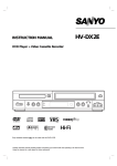
Buttons:
Number
1
2
3
4
5
6
7
8
16
CHA/CHB/T1/T2
Functions
MAX/MIN
HOLD
Hi Lo
REL U
ESC
+/SAVE
CANCEL
LOG
ALM LOG
Main Function
2nd Function
MAX/MIN
Move to left
Data hold
Move to right
Alarm when out of set limits
Move upward
Display relative value
Move downward
Backlight On/OFF
Exit
Single record
Change between positive and negative
Continuous record
Abandon setup
Record the out of limit data
and time
Enter
5
Rotary Switch:
1. Off position.
2. Work position.
3. Main/2nd/3rd display setup.
4. Sockets of K type thermocouples T1 and T2 setup.
5. RTD (CHA) setup.
6. ADAPTER (CHB) setup.
7. Data processing.
8. Battery test.
9. Setting.
Press direction keys
or
to change the indicator among “READ MEM SAVE”, “READ
MEM LOG” and “READ MEM LIMIT”.
Press “ ” key to enter the indicated set of recorded data.
In “READ MEM SAVE” and “READ MEM LIMIT”, press direction keys
or
to move
among the data with the measurement reading shown in main display, sequence number in second display and time in third display.
There may be more than one group of data in “READ MEM LOG”, right after entering
or
to move
“READ MEM LOG” data, second show GRP 0001, press direction keys
among the different group of data, press “ ” key to enter the group indicated in second display.
Press direction keys
or
to move to the data of different channels in the same record and
press direction keys
or
to move among the different records of same channel.
Press “ESC” button to leave “VIEW” function and return to “Memory Access Functions Selection mode” with blinking indicator “SET” at upper-right corner.
or
to change the blinking indicator to “SET” (SET function) or
Press direction keys
“CLR” (Memory Clear function), or to leave this function by turning the Rotary Switch to another position.
SET (SET function : Select the channels for data logging)
When the blinking indicator shows “SET”, press “ ” key to enter SET function. The indicator “SET” stops blinking and another small indicator “SET” appears at left side of LCD.
4. Battery Installation
Remove the two screws from the back of the meter and lift off the battery case.
Note: When there is data in the memory, you can not enter “SET” function.
To erase recorded data, please execute “CLR” function mention above.
Right after entering “SET function”, previously selected channel is shown at top of LCD.
or
to change the channel among “T1”, “T2”, “CHA”, “CHB”,
Press direction keys
“T1T2”, “CHA T1T2” and “CHB T1T2”.
Press “ ” key to confirm selection and return to function selection with indicator “SET”
blinking at upper-right corner of LCD.
or
to change the blinking indicator to “CLR” (Memory Clear
Press direction keys
function) or “VIE” (VIEW function), or to leave this function by turning the Rotary Switch to
another position.
Note:
It is need to replace the battery less than 20 sec. to avoid the time of system was reset.
6
Note: When single channel (i.e. T1 or T2 or CHA or CHB) is selected, the selected channel
will be automatically assigned to Main Display and overwrite the previous setting of Main Display. When multi channel (i.e. “T1 T2” or “CHA T1 T2” or “CHB T1 T2”) is selected the first
channel (i.e. T1 for “T1 T2” or “CHA” for “CHA T1 T2” or CHB for “CHB T1 T2”) will be
automatically assigned to Main Display and overwrite the previous setting of Main Display.
If you do not want this automatic assigned channel shown in Main Display, please re-set the
Main Display (see section 8.1 for setting Main Display). This resetting of Main Display does not
influence the set channel(s) for data logger.
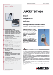
15
01
T1
NOTE :
Press “ESC” or “cancel” button or turn Rotary Switch to
another position before finishing SET and CLR function ;
previous setting and recorded data will remain unchangeed.
003
CHA
SET
004
CHB
05
T1+T2
Shown channel(s) selected
Main Display Reset ( * )
Place Rotary Switch at MEM VIEW CLR
position to enter Memory Access Function
02
T1
1.
2.
* Please refer note of 8.12 (page 13)
5. Turn On and Off Model 506A:
006
CHA+T1+T2
Power is off when the “Rotary Switch” points to the upper center, the position marked with
“{”, turning the rotary switch to any other position automatically turns on Model 506A5. Numbers and marks appear in the LCD display.
#0001
007
CHB+T1+T2
When APO (Auto Power Off) is enabled (refer to 8.17 for enable and disable of APO), power
is automatically turn off if no operation for a period of time. (Factory setting = 5 min. settable by
user).
VIE
SAVE
#0001
#XXXX
#XXXX
Indication of APO Enabled
LOG
GRP
0001
6. Check battery Voltage:
LIMIT
#0001
GRP
XXXX
#XXXX
Place the rotary switch at the position “BATT TEST”, main display shows the voltage of battery.
CLR
YES
Memory
Cleared
14
7. Measurement and Main Function of Buttons
Place the rotary switch at “MEAS” position, the meter starts to measure.
Main display shows the measurement reading of the channel assigned to main display. (to select
channel for main display, please refer to 8.1)
While measuring, press push buttons to change the function of main display and perform record functions.
7
8.11 CHB RANGE-Select the Resolution for Cannel B (CHB)
Channel B can accept the voltage signal up to 2 volts; above 2 volts display shows OL. Place
the rotary switch at position “CHB RANGE”, change among Auto (“--.-.-” and “AUT” is shown
in display), “0.1” (“---.-” and “MAN” is shown in display) and “0.01” (“--.—” and “MAN” is
shown in display).
When “Auto” is selected, the meter will select most suitable resolution between “0.1” and
“0.01”, while the other two, the reading will be fixed in the selected resolution.
7.1 MAX/MIN : (This function only applies to the channel shown in main display)
Pressing “MAX/MIN” button, the indicator “REC” appears at right side of LCD, the meter
will start to record the Maximum and Minimum values and calculate average value of measurement reading.
Press “MAX/MIN” button again each time, main display changes from current measurement
reading to maximum value recorded with indicator “MAX” below “REC”, minimum value recorded with indicator “MIN” at lower right side of “REC”, the difference between maximum and
minimum values with indicator “MAX-MIN” below “REC”, the average value during recording
with indicator “AVG” right to “REC”, and then back to current measurement reading.
Press and hold the “MAX/MIN” button for longer than 5 seconds to end the MAX/MIN recording.
7.2 HOLD : (This function only applies to the channel shown in main display)
Press the “HOLD” button, the display holds the current reading and the meter stops further
measurement. Indicator “HOLD” is shown at top of the LCD.
Press the “HOLD” button again to release from the holding function and resume normal measurement.
7.3 Hi/Lo : (This function only applies to the channel shown in main display)
Press the “Hi/Lo” button, to activate the out of limit alarm function. The indicator “LIMIT” appears at right side of LCD.
When the measurement value is higher than upper limit the beep send out an intermittent sound.
When the measurement value is lower than lower limit the beep send out a continuous sound.
Press the “Hi/Lo” button again, to disable the alarm function.
Refer to 8.15 for setting upper and lower limits.
7.4 REL Δ : (This function only applies to the channel shown in main display)
REL Δ: (This function only applies to the channel shown in main display)
Press “REL Δ” to store the current value as the reference, relative value against this reference
will be displayed for the measurements afterward.
:
7.5
Press this button to turn on the backlight function, press it again to turn the backlight off.
7.6 LOG (Data Logging) :
During measuring, press “LOG” button to continuously record the measurement readings of
the set channels at the set time interval until the “LOG” button is pressed again.
To set the channel for LOG function, please refer to section 8.12
To set the time interval for LOG function, please refer to section 8.18
To read the logged data, please refer to section 8.12
8
8.12 MEM VIEW CLR - Selecting the channel for data logging, Read recorded data and
Clear memory
There are 3 functions in this position “MEM VIEW CLR” :
1. SET function: Select the channels for data logging.
2. VIEW function: To read recorded data.
3. Memory Clear function: Clear memory and erase all the recorded data.
Place rotary switch at position “MEM VIEW CLR”, the meter enter the “Memory Access
Functions Selection Mode” with LCD shows the indicator “MEM” at lower-right corner and a
blinking indicator “SET” at upper-right corner.
or
to change the blinking indicator among “SET” (SET funcPress direction keys
tion), “VIE” (VIEW function) and “CLR” (Memory Clear function).
To exit this function, just turn the Rotary Switch to another position.
CLR (Memory Clear function: Clear memory and erase all the recorded data)
When the blinking indicator shows “CLR”, press “
ing indicator changes to “YES”.
” key to enter Clear function. The blink-
Press “ ” key to clear memory and erases all the data recorded in the memory (this will take
some seconds), and return to “Memory Access Functions Selection mode” with blinking indicator “SET” at upper-right corner.
Or press “ESC” key to abort the job and keep the data in the memory unchanged, and return to
“Memory Access Functions Selection mode” with blinking indicator “SET” at upper-right corner.
or
to change the blinking indicator to “SET” (SET function) or
Press direction keys
“VIE” (VIEW function), or to exit this function by turning the Rotary Switch to another position.
VIE (VIEW function : to read recorded data)
There are 3 sets of data you can choose to read, namely “SAVE”, “LOG” and “LIMIT”, (corresponding to the functions of buttons “SAVE”, “LOG” or “ALMLOG”, respectively. Please refer to section 7.6, 7.7, 7.8 for the functions of these buttons.)
When the blinking indicator shows “VIE”, press “ ” key to enter VIEW function. The
blinking indicator “VIE” disappears. Indicators “READ MEM” and “SAVE” are shown at
lower-right corner of LCD.
13
8.9 CHB TYPE-Select the Unit for Channel B
CHB only shows the voltage, and the unit represented by this voltage has to be given. At position “CHB TYPE”, change the unit with upward ( ) or downward ( ) direction buttons among
AAA, →°C→ppt→μs→ms→s→FPM→%RH→%→ppm→mV→V→μA→mA→A→ohm.
The first unit, AAA, can be redefined by user for other special unit, see next section. Press the
confirm button ( ) to select the unit. The selection is kept even power turned off.
CHB is for a transducer with output of 1 mV = 1 “unit”.
CHB always measures the input voltage with mV.
The “unit” is only a human readable indicator for the convenience of user, it does not change
the measurement.
The “unit” can be set as “mV” or “V” or “%RH” or “%” or “ohm” or “ABC”, and it only make
sense when it is set according to the output property of the transducer.
For example if we connect a humidity transducer with output 1 mV = 1 %RH to the CHB
(channel B) of the meter, the “unit” should be set as “%RH”. If user does not do so, then the
the unit becomes meaningless, but the measurement will not influenced.
8.10 CHB PARA-Create Special Unit for Channel B (CHB)
Changing each individual character of “AAA” to one of following can create special units.
(Characters available: upper case characters A to Z, lower case a to z, o, /, %, μ, dot and blank
space).
Place rotary switch at position “CHB PARA”, This user defined unit (set as “AAA” when
shipment) shows at right-upper corner of LCD with the left character blinking. The blinking character can be changed with upward ( ) or downward ( ) direction buttons.
With right ( ) or left ( ) direction buttons, the blinking can be moved to another character. After all 3 character are changed to the desired ones, press confirm button ( ).
7.7 SAVE :
SAVE: This function only apply to the channel shown in main display. And not function when
LOG function is set as multi-channel logging.)
During measuring, press “SAVE” button to record current measurement reading of the channel
shown in Main Display and time.
To read the recorded data, please refer to section 8.12
To set the channel for Main Display please refer to section 8.1
To set the channel for LOG function please refer to section 8.12
7.8 ALMLOG: (This function only apply to the channel shown in main display. And not
function when LOG function is set as multi-channel logging)
Every time when the measurement reading of the channel shown in Main Display the Alarm
Log function records the first measurement reading which is out of limits and time, when the
measurement value returns to within the limits the last out of limit data and time will also be recorded.
Press the “ALMLOG” button, to activate the alarm log function, and the indicators “LIMIT” and
“LOG” are shown at lower-right corner of the LCD.
Press the “ALMLOG” button again to disable this function.
To read the recorded data, please refer to section 8.12
To set the channel for Main Display please refer to section 8.1
To set the channel for LOG function please refer to section 8.12
8. System Setting and second Functions of Buttons:
Except these 3 positions mentioned above, all other position are for system setting, the indicator
“SET” shows at left side of LCD when place the rotary switch at any of these system setting positions. And 2nd functions of buttons are active.
8.1 D1-Setting the Main Display
Main display can be set to show the reading of any of the 4 channels. Place rotary switch at position “D1”, and select the channel with “right ( )”or “left ( )” direction keys to change the channel. “D1”, name of active channel is shown at top of LCD. Press “CANCEL” button to back to
previous setting. Press “ESC” button to abort change and exit the setting mode with previous setting remains unchanged. Confirm selection and exit setting mode by pressing “confirm ( )” button.
Main Display
(AUTO)
(MANUAL)
12
9
8.2 D2-Setting Second Display (Lower-Left Display)
Second display can be set to show the reading of T1 or T2. When the power is turn on, the meter remains in the previous setting. Turn the rotary switch to the position “D2”, and use right ( ) or
left ( ) direction buttons to change between T1 and T2.
Second Display
8.3 D3-Setting Third Display (Lower-Right Display)
Third display can be set to show the value of T1-T2, Date (YY: MM: DD) and time
(HH:MM:SS). When the power is turn on, the meter remains in the previous setting. Turn the rotary switch to the position “D3”, and use right ( ) or left ( ) direction buttons to change between
T1 and T2.
Third Display
8.4 T1 TYPE and T2 TYPE-Selecting the Types of Thermocouple for T1 or T2
Both T1 and T2 can accept the thermocouples of type K, J, T, E, R, S and N. When the power is
turn on, the meter remains in the previous setting.
Turn the rotary switch to the position “T1 Type” or “T2 Type”, current selection is shown at upper-right corner of LCD, adjacent to unit of temperature, change type of thermo couple with
upward ( ) or downward ( ) direction buttons after right type is shown, and press confirm key
( ) to select.
8.6 CHA TYPE-Selecting the Types of RTD for CHA
Besides accepting the RTD of type Pt 385, Pt3916 and Pt3926, this meter can also display the
resistance value in ohm ( ) of the sensor.
When the power is turn on, the meter remains in the previous setting. Turn the rotary switch to the
position “CHA-Type”, current selection is shown at left side of LCD for RTD sensors and right
hand side, for ohm. Change the types with upward ( ) or downward ( ) direction buttons after
right type is shown, press return key ( ) to select.
8.7 CHA ADJ-Setting the Off-Set Adjustment for RTD
If the off-set error of your RTD is known, the off-set adjustments to the channel A (CHA).
Place the rotary switch at positions “ADJ” just below “CHA-Type”.
Select the digit you want to adjust with right ( ) or left ( ) direction buttons, (Setting of the adjustment value is done one individual digit after the other).
Change the value of blinking digit with upward ( ) or downward ( ) direction buttons. After
reach desired value, press return key ( ) to confirm.
8.8 CHA RANGE-Select the Resolution for Channel A (CHA)
Place the rotary switch at position “CHA RANGE”, change among Auto (“--.-.-” and “AUT” is
shown in display) and “0.1” (“---.-” and “MAN” is shown in display) and “0.01” (“--.--” and
“MAN” is shown in display).
When “Auto” is selected, the meter will select most suitable resolution between “0.1” and
“0.01”, while the other two, the reading will be fixed in the selected resolution.
RTD TYPE
8.5 T1 ADJ and T2 ADJ-Setting the Off-Set Adjustment for T1 or T2
If the offset error of your thermo couples, and to which socket those particular thermocouples
are known, the offset adjustments can be set to each of T1 and T2 for compensating the off-set error.
10
11