1
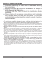
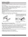
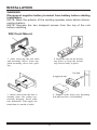
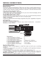
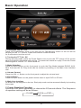
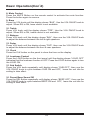
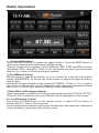
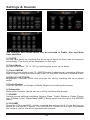
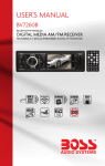
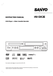
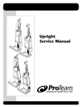
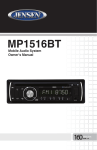
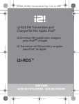
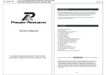
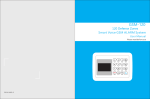
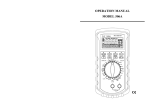
Thank you for choosing Boss Audio Systems! This unit will
bring you years of enjoyment.
CONTENTS
Safety Precautions.................................................................2-3
Installation.............................................................................4-6
Wiring Connections...................................................................7
Controls Of The Unit...................................................................8
Basic Operation....................................................................9-10
Radio Operation..................................................................11-12
DVD/VCD/CD/MP3/WMA Operation..................................13-17
Setings & Sound.......................................................................18
Other Operation.......................................................................19
Maintenance...........................................................................20
IR Remote Control...................................................................21
Troubleshooting Guide..........................................................22
Specifications..........................................................................22
SAFETY PRECAUTIONS
Important Warnings to Take Note of BEFORE Starting
the Installation
Damage Caused By Incorrect Installation or Usage is
NOT Covered By Warranty.
PLEASE Take the Time to Read the Installation Notes
Carefully.
Please make all necessary connections and terminate
any unused wires so they do not short. If you feel
uncomfortable preforming the install consult a professional installer.
To avoid any possible damage to your vehicles electrical system, be
sure to disconnect the battery cable before beginning installation.
The unit is intended for vehicles with a 12-volt battery and negative grounding.
Before installing the unit in a recreational vehicle, truck, or bus, check that the
battery voltage is 12 volts.
Remove the two transport screws from the top of the unit before installation.
Be sure to connect the negative (-) speaker leads to the negative (-) speaker
terminal. Never connect the negative (-) speaker leads to chassis ground.
This unit is only designed for use with 4 speakers. Do not combine outputs
for use with 2 speakers. Do not ground negative speaker leads to the chassis
ground.
Speakers connected to this unit must be 4 to 8 ohms. Connecting speakers
with output and/or impedance values other than those noted there will result
in damage to the head unit and the speakers.
Check the condition off your speakers carefully - connecting the unit to
old of degraded speakers may result in a fault which will damage the
audio IC and invalidate the warranty.
If this unit is installed in a vehicle that does not have an ACC (accessory)
position on the ignition switch, the red lead of the unit should be connected to
a terminal coupled with ignition switch ON/OFF operations. If this is not done,
the vehicle battery may be drained when you are away from the vehicle for
several hours.
2
SAFETY PRECAUTIONS
Secure the wiring with zip ties or electrical tape. . To protect the wiring, wrap
adhesive tape around them where they lie against metal parts. To avoid
short-circuiting, cover all disconnected lead with insulating tape. There is a
possibility of short-circuiting if the leads are not insulated.
Route and secure all wiring so it cannot touch any moving parts, such as the
gear lever and handbrake. Do not route wiring in places that get hot, such as
near the heater outlet. If the insulation of the wiring melts or gets torn, there is
a danger of the wiring short circuiting to the vehicle’s body.
Don’t pass the yellow lead through a hole into the engine compartment to
connect to the battery. This will damage the lead’s insulation and cause a very
dangerous short.
Do not shorten any leads, if you do, the protection circuit may fail to work
when it should.
Never feed power to other equipment by cutting the insulation of the power
supply lead of the unit and tapping into the lead. The current capacity of the
lead will be exceeded, causing overheating.
Since a unique audio I/C circuit is employed, never wire so the speaker leads
are directly grounded or the left and right - speaker leads are common.
When this product’s source is switched ON, a control signal is turned on
through the Blue/White lead. Connect to an external power amp’s system
remote control or the car’s Auto-antenna relay control terminal (max. 500mA
12V DC).
Do not block any vents or heater panels, Blocking them will cause heat to build
up and may result in fire.
When replacing the fuse(s) the replacement must be of the same amperage
as shown on the fuse holder. Never replace a fuse with another of a different
value. If the fuse blows again please contact your instsallation company.
Double check that all wiring and connections are correct before re-connecting
the battery and turning on the unit.
After completing the installation and before operating the unit, reconnect the
battery, then press the (RES) button with a pointed object, such as a ball-point
pen to set to unit to it’s initial status. After pushing the button, wait a few seconds for the red light to flash.
3
INSTALLATION
Tools for Installation
2 removal wrenches are supplied for taking out the old unit and place with this
brand name car radio. The following tools and supplies may also be needed for
the installation:
Tools for Installation: Philips Screw-drivers /Machine Screws /Wire Stripper
/Wire Cutter /Hammer /Pencil /Electrical Tape /Electric Drill
Supplies for Installation: Machine Screws /Crimp Connectors /14 Gauge Wire for
Power Connections /14-16 Gauge Speaker Wires
The above are not supplied.
Before you install
We strongly recommend that this unit should be professionally installed by a VAT
registered installer (this is a requirement to validate the warranty).
IMPORTANT: Remove the two transport screws from the top fo the unit before
installing.
Remove the Old Unit from the Dashboard
2. Insert the keys supplied with the
old unit into both sides of the unit
as shown in figure below until
they click. Pull to remove the old
unit from the dashboard.
1. Remove the outer trim frame.
DIN Front Mount
DO NOT DISCONNECT WIRES
AT THIS TIME!
Mark Polarity of the Speaker Wires
Marking the polarity of the speaker wirers will make it easier to connect the
existing speakers to your car radio. Consult wiring diagram of existing head
unit before disconnecting any wires. If you are not positive of the polarity of the
existing wires from the speakers to the head unit, install new wires.
1. While the old unit is playing, disconnect the wires from one speaker.
2. Take a length of masking tape and fold it around the wire so it forms a flag.
3. On the masking tape mark the polarity of the speaker wires (+&-), as well as
left or right, and front or rear.
4. Double check that you marked the first speaker correctly by checking that the
speaker wires are the same at the head unit.
5. Repeat this procedure for all of the speakers.
6. Mark the power, ground, and any other wires also.
4
INSTALLATION
WARNING!
Disconnect negative battery terminal from battery before starting
installation.
NOTE: Mark the polarity of the existing speaker wires before disconnecting battery.
NOTE: Remove the two transport screws from the top of the unit
before installing.
DIN Front Mount
1. After removing the old radio
and mounting sleeve, insert supplied mounting sleeve into opening.
2. Bend the tabs on the mounting sleeve to keep the mounting sleeve firmly in place.
3. Attach wires from the unit to
existing wires. See wiring connections diagram. Insert radio
into dashboard. Then apply the
trim frame to outside of radio.
4. Support radio using rear mounting
bolt and steel bar. (not included)
5
INSTALLATION
DIN Rear Mount
NOTE: Outer trim frame, hook, and mounting sleeve are not used
for this installation
This is only intended as a general guide; contact the vehicle’s manufacturer for
specific instructions.
This menthod of installation uses the screw holes at the sides of the unit and
the holes of the existing vehicle mounting bracket.
1. Remove the hooks on both sides.
2. Aligh the screw holes of the mounting bracket supplied with the car and the
screw holes of the main unit. Tighten the 2 screws on each side of the unit.
Then fasten the brackets to the car.
3. Attach wires of the unit to existing speaker wires. See wiring diagram.
6
WIRING CONNECTIONS
General Wiring Notes:
Black Ground
Connect to vehicle body/chassis. Make sure you have a good chassis ground.
This will eliminate most electrical noise form the motor and alternator. A good
chassis ground requires a tight connection to ground. The area should be free
from rust, paint or any form of dirt.
Light Green (Hand Brake - Ground)
Connect this wire to the hand brake wire of your car so that the display will be
on only when the car is fully stopped.
Purple-White (Rear Gear - VCC)
Connect this wire to the rear gear wire of your car so that the backup camera
function can be activated when you car is in reverse gear.
Yellow “Constant”
Connect to electrical terminal always supplied with power regardless of ignition
switch position.
Blue/White Remote Output (+)
Connect to Auto-antenna or power amp control wire/remote connection.
Maximum current 500mA.
Brake (Light Green)
Reverse (Purple-White)
Connector A
1. Rear right speaker(+)/Purple
2. Rear right speaker(-)/Purple-Black
3. Front right speaker(+)/Grey
4. Front right speaker(-)/Grey-Black
5. Front left speaker(+)/White
6. Front left speaker(-)/White-Black
7. Rear left speaker(+)/Green
8. Rear left speaker(-)/Green-Black
Connector B
1. 2. 3. 4. Battery 12V (+)/Yellow
5. Remote Trigger/Blue-White
6. 7. ACC+/Red
8. Ground/Black
Speaker Wiring Notes:
Follow the above wiring diagram to install the head unit with new or existing
speakers.
1. This unit is designed for use with four (4) speakers with impedance between
4 Ohms to 8 Ohms.
2. An Impedance load of less than 4 Ohms could damage the unit.
3. Never bridge or combine the speaker wire outputs. When not using four
speakers, use electrical tape to tape the ends of the unused speaker outputs to
prevent a short circuit.
4. Never ground the negative speaker terminals to chassis ground.
7
Controls Of The Unit
8
Basic Operation
1. Tuning the unit On / Off
Press the Power button once to turn the unit on. The opening screen of the unit will be
showing on the TFT monitor. Press and hold the POWER button
for 2 seconds to turn the unit off.
2. Turning the TFT On / Off
During any play mode, press the Power Button once to turn the TFT screen off for screen
saving and avoid distraction while driving. The sound will continue to play. Press the Power
Button again to turn the TFT screen back on.
3. Mode Selection
Press the MOD Button on the front panel to cycle the Play Mode between RADIO, AUX,
Blue Tooth and AV IN. Play mode can be chosen by touching on the Main User Interface
also.
4. Volume Control
Press the VOL +/- Button on the front panel to adjust the volume level.
5. Eject Button
Press the Eject Button on the plastic bottom case to eject DVD or CD disc.
6. Main User Interface
As shown on the diagram on the top. Each play mode can be accessed directly by touching
the screen.
7. Preset Equalizer Function
Press the VOL knob repeatedly to choose the EQ sound effects. The Sequence
of equalizer setting will be as follows:
CLASS
ROCK
POP
OFF
9
Basic Operation(Con’d)
8. Mute Control
Press the MUTE Button on the remote control to activate the mute function.
Press the button again to resume.
9. Bass
Press the VOL knob until the display shows “BAS”. Use the VOL DN/UP knob to
adjust. When EQ is ON, bass control is not available.
10. Treble
Press VOL knob until the display shows “TRE”. Use the VOL DN/UP knob to
adjust. When EQ is ON, treble control is not available.
11. Balance
Press VOL knob until the display shows “BAL”, then use the VOL DN/UP knob
to adjust the balance between the left & right speakers.
12. Fader
Press VOL knob until the display shows “FAD”, then use the VOL DN/UP knob
to adjust the balance between the front & rear speakers.
13. Clock
Press the CLK button on the panel to show the time on the display.
14. Loudness Control
Press the LOUD button on the front panel until the display shows “LOUD OFF”
indicates that the loudness function is OFF. Press the LOUD button again to turn
the LOUD ON.
15. Sub Switch
Press the VOL knob repeatedly until display shows “SUB OFF“, then use the
VOL DN/UP knob to cycle between SUB ON and OFF, leave the unit idle for
setting to take effect.
16. Preset Beep Sound Off
Press the SEL button repeatedly until display shows “BEEP OFF”, then use the
VOL DN/UP knob to cycle between BEEP ON and OFF, leave the unit idle for
setting to take effect.
10
Radio Operation
1. Choose Radio Band
Press the MOD Button to access the radio function. Press the BND button to
select your desired radio band during RADIO mode.
The unit comes with five bands- three FM Bands (FM1, FM2, and FM3) and two
AM Bands (MW1, and MW2). Each of the five bands can store up to six preset
stations, for a total of 30 preset memory stations.
2. Auto/Manual Tuning
Manual tuning: Press and hold the >>| or |<< button for a second until display
shows “MANUSEEK“ on the left top of the screen to adjust the radio frequency
step by step.
Automatic tuning:In default tuning mode(AUTOSEEK), Press >>| or <<| (left or
right arrow on the screen) once to adjust the radio frequency automaticly. Press
the >>| or <<| (left or right arrow on display) to stop searching.
3. Mono/Stereo Reception Control
Under radio mode, touch MO/ST button on the screen to select ST:ON or ST:OFF.
When ST:OFF is selected, the word “MONO” will be displayed on the screen.
4. Local/Distance Control
Press the LOC/RDM button on the remote control or press LOC/>|| button to
select LOCAL or DX on the front panel.
Local and distance reception setting can facilitate the radio reception, depending
on the location in which the radio is being used.
11
Radio Operation(Con’d)
5. Save Your Preset Stations
There are six numbered preset(P1-P6) buttons when you enter radio mode
which can store and recall stations for each band. While listening to a radio
station you would like to save as a pre-set, touch one of the buttons numbered
P1-P6 until you hear a beep. The button you pressed is now the pre-set button
for that station.
6. Automatic Store/Preset Scan
A. Automatic Scan & Store
Press and hold the APS Button for 3 seconds. The receiver will automatically
scan and save the 6 strongest available stations as the 6 preset memories of the
current band. To stop auto store, press this button again.
B. Scan Saved Stations
Press the APS button on the front panel or touch APS button under radio mode
to scan all preset stations in the memory of the current band and stay on each
memory stations for about 5 seconds. To stop preset scan, press this function
again. To listen to saved station touch P1-6 button on the screen.
12
DVD/VCD/CD/MP3/WMA Operation
1.Insert / Eject CD
Press “Open” button, the front pannel of the unit will slip down and then
insert a disc into CD slot with label side up. The disc will be automatically
loaded into the unit, even when it is off or at radio mode. Then close the
front panel. The word “LOAD” will be shown on the display and the CD will
play automatically. Press “Open” button, the front pannel of the unit will
slip down , then press EJECT Button to eject the disc from the slot. If the
disc is not removed from the slot within 5 seconds, it will automatically be
loaded into the slot again. When the disc is ejected and removed, the unit
will automatically switch to radio mode.
A. While you are playing DVD, after the disc is loaded, the media of the
DVD will be played automatically. The menu will be prompted so that you
can choose the setting. You can also press the PBC button on remote control during playback to return to the opening screen to get the menu. The
disc will go back to the opening screen if PBC button is pressed.
B. While you are playing CD, the monitor will show the details as PIC 01:
PIC 01
PIC 02
However, when you under MP3 mode, you could use the navigation “↑” “→” “←”
“↓” button from remote control ( or touch directly the song what you want on the
screen) to select the song you would like to listen, then press the ENTER button
to confirm your selection.
C. While you are playing MP3/WMA in DVD/CD/USB/SD, the monitor will show
the details as PIC 02 :
D. While you are playing DVD/CD/USB/SD which contains MP3, WMA, JPG
or DIVX formats, after insert the disc into the CD Slot, the unit will directly play
the audio files. To select the format amoung music, picture, video, and then you
can use the navigation “↑” “→” “←” “↓” button From the remote control( or touch
directly on the screen) to select the file that you would like to view/listen to and
press the ENTER button to confirm your selection.
Picture of playlist menu (see PIC 02)
13
DVD/VCD/CD/MP3/WMA Operation(Con’d)
2. OSD (ON-Screen Display)
While playing DVD/VCD, press OSD button On the remote control or touch
the screen directly to activate the OSD.
A. For VCD, the monitor will show the details as PIC 03 :
B. For DVD, activate OSD for the first time, the monitor will show the details as PIC 04 :
activate OSD for the second time, the monitor will show :
Press again to turn the OSD off, leave it for 5 seconds, the unit will turn off
the OSD automatically.
3. Title / PBC Playing
Press the TITLE button on the remote control so that the first title track of the
DVD will be played. After playing, the current running track will be resumed. For
VCD2.0, press the PBC button on the remote control while the disc is playing.
You can switch between PBC on and PBC off mode.
4. Selecting Tracks
Press SEEK >>| or SEEK |<< On the Remote Control, Track numbers will be
shown on the display. Press and hold the SEEK |<< Button to fast reverse. Disc
will play normally when the SEEK >>| or SEEK |<< Button is released.
5. Play/Pause
Press the LOC/>|| button on the unit or >|| button from the remote control to call
the setup menu.
6. Audio Selection
Under DVD/VCD mode, press APS button on the unit or AUDIO button on the
remote control, in order to choose the audio language. The audio languages
available differ from Disc to Disc. You can also use the setup menu to confirm.
Refer to the packing of the Disc for details.
7. Subtitle Language
Press the SUB-T button on remote control to select the subtitle language you
want. The sub-title languages available differ from Disc to Disc. You can also
use the setup menu to confirm. Refer to the packing of the Disc for details.
14
DVD/VCD/CD/MP3/WMA Operation(Con’d)
The audio languages available differ from Disc to Disc. You can also use the
setup menu to confirm. Refer to the packing of the Disc for details.
VCD: Press AUDIO during playbackIt is possible to switch the sound
between mono and stereo sound. The sequence is as follows:
Mono Left --> Mono Right --> MIX MONO --> STEREO
8. Track Time Search
Press the GOTO button on the remote control to search the desired track
time to play the Disc. The OSD will be prompted. Make use of the navigation
keys and digit keys on the remote control to choose your desired chapter,
track or time. Press the ENTER button to confirm your selection.
9. Zoom +/Press the ZOOM button on the remote control to perform the zoom function.
The zoom range is from 1/4 up to 4 (total 7 stages), according to the zooming
intensity.
10. Slow Motion
Press the SLOW button on the remote control to perform slow montion of the
video play. SF 1/2 up to 1/7 will be shown, according to the slowness. Cycle
back to normal playback of press the Play/Pause button to resume.
11. Multi-Angle View
Press the ANGLE button on the remote control to perform multi-angle playback. The number of angles change in sequential order.
Note: The number of angles is different according to the disc. The function
only work for discs having scenes recorded at different angles. When no
different angle is recorded, the OSD will show “INVALID KEY”
12. Video System
Press the BND/NP/SUB button on the headunit or remote control to choose
between NTSC, PAL, AUTO, according to the encoding format of the disc.
The default mode is AUTO. Use this function if there is something wrong
about the display function (eg. no color is display).
13. Programmer Mode
Press the PROG button on the remote control to set the program play. Use
the Navigation and Digit keys to set the Chapter and Track no. as your
desired sequence. Press Enter to begin the program play. Press the PROG
button and confirm a blank program again to cancel this operation.
14. Electronic Shock Protection
This unit is programmed with Electronic Shock Protection (ESP) so that
the video/music will be protected against rough roads. Electronic Shock
Protection time depends on the media that is being played. ESP for playing
DVD is 5 seconds, for playing VCD is 10 seconds, for playing CD is 12 seconds, for MP3 is 180 seconds. This is built-in function so that there is no need
to switch on or switch off.
15
DVD/VCD/CD/MP3/WMA Operation(Con’d)
15. Returning to Main User Interface
Press the arrow on the right hand side of onscreen menu p.1 to return to the
main user interface.
Onscreen Menu
SETUP MENU
The functions of the setup menu will be briefly described as follows:
1. Functions of the setup menu are as follows:
From Left to Right:
A. System setup /B. Language setup /C. Audio setup /D. Video setup
A. SYSTEM SETUP
a. TV SYSTEM -- This player can play discs recorded in either PAL or NTSC
format. Select NTSC format when you are connected to NTSC TV. Select
PAL format when you are connected to PAL TV. If you select AUTO, the unit
will auto select the format according to you TV System.
b. SCREEN SAVER -- Choose the screen saver on or off.
c. TV TYPE -- This is to select the appropriate TV aspect (4:3 or 16:9)
according to the connected TV set.
i) 4:3 PS -- Played back in the PAN & SCAN style. (If connected to widescreen TV, the left and right edges are cut off.)
ii) 4:3 LB -- Played back in LETTERBOX style. (If connected to wide-screen
TV, black bands appear at top and bottom of the screen)
iii) 16:9 -- Select when a wide-screen TV set is connected.
d. PASSWORD -- Press the STOP button for two times during playback, so
that the disc play is completedly stop. Press the right, left, down, up buttoms
orderly, then the setup menu for password will be prompted for you to set up
the new password.
e. RATING -- Select Suitable guidance rating by the cursor button and confirm by pressing ENTER button.
Rating 1: [Kid Safe] -- Select it if the programs are safe to all kids view.
Rating 2: [G] -- Select it to indicate that it allows admission to person of all
ages.
16
DVD/VCD/CD/MP3/WMA Operation(Con’d)
Rating 3: [PG] -- Select it to indicate that it needs parents to guide their
children.
Rating 4: [PG_13] -- Select it to indicate that children under 13 are forbidden to view.
Rating 5: [PG_R] -- Select it if “PG_R” was printed on the DVD disc.
Rating 6: [R] -- Select it to indicate that children under 17 must be guided
to view by their parents.
Rating 7: [NC-17] -- Select it to indicate that children under 17 are forbidden to view.
Rating 8: [ADULT] -- Select it to indicate that only adults are permitted to
view.
B. LANGUAGE SETUP
Select the preferred OSD Language, Audio Language, Subtitle Language
and Menu Language by using the navigation buttons. The default language is in English. Please refer to the setup tree to select language of
the following catagories:
a. OSD Language /b. Audio Language /c. Subtitle Language /d. Menu
Language
C. AUDIO SETUP
a. AUDIO OUT
This is to activate the audio output from ANALOG/OPTICAL mode to SPDIF/
RAW mode or SPDIF/PCM mode.
i) SPDIF/OFF
Analog or Optical output port all has not output signal.
ii) SPDIF/RAW
When the player is connected with the power amplifier by the analog or optical port, please select this item; when the playing disc which is recorded by
Dolby Digital, DTS or MPEG recording system, the analog or optical output
signal of the unit will be the same as the digital signal (RAW format) of the
playing disc. At the same time, the power amplifier you connected must have
the decode fuction of Dolby Digital, DTS or MPEG.
iii) SPDIF/PCM
When the player is connected with the 2 channel, digital stereo amplifier,
please select this item; when the playing disc which is recorded by Dolby
Digital or MPEG recording system, the analog or optical output will be modulated to 2 channel output by PCM.
b. KEY
This is to select key up and down according to your needs.
D. VIDEO SETUP
This is to let the user set Brightness, Contrast, Hue, Saturation and
Sharpness using the navigatio keys. Press ENTER button to confirm the
setting of the video. The sequence of the video setup is as follows:
a. BRIGHTNESS
b. CONTRAST
c. HUE
d. SATURATION
e. SHARPNESS
17
Settings & Sounds
The Settings and Sound menu can be selected in Radio, Aux and Main
User Interface.
1. CLOCK
Set the time clock by touching the arrow up or down for hour and min session
accordingly. The clock will be displayed on the right.
2. Clock Mode
Set the time mode “12“ or “24“ by touching the arrow up or down.
3. Clock AM/PM
When the clock mode is set 12, AM/PM button is able to set, indicating different
time of a day; When the clock mode is set 24, the AM/FM button is inactive to set.
4. DISPLAY SETTINGS
Brightness, Contrast, Color and Hue can be set by touching the up or down
arrow.
5. Radio Region
You can set USA or Europe in Radio Region by touching the arrows.
6. Subwoofer
Subwoofer function can be set on or off by touching the arrows.
7. SOUND
Various sound settings including Volume, Bass, Treble, Balance, Fader, Equalizer, D-Bass, Loud, Super Bass (MBP), Beep on/off can be set in the SOUND
menu.
8. VOLUME
Press the VOL+ and VOL- button to adjust the volume level. It can also be selected by the SELECT button. Turn the SELECT button to the right to increase
the volume, and to the left to decrease the volume.
18
Other Operations
1. Front Pre-amp Output x 4
The RCA Output Jack is on the back of the unit. (Refer to Wiring Diagram)
This output is for connecting amplifier, equalizer, or other audio component that
requires a pre-amp out connection. (Red=Right, White=Left) Follow the manufactures instructions for the audio component that you are connecting.
2. Video Output(Rear) x 1
The Video Output Jack is on the back of the unit. (Refer to Wiring Diagram) This
output (in yellow) is for connecting monitor(s). You must connect a monitor for
car in order to play this unit in another monitor. Consult your dealer for any kinds
of monitors that are suitable to use in car. Press the “BAND” button to choose
between PAL and NTSC mode.
3. Backup Camera Input(Rear) x 1
The backup camera input is on the back of the unit. (refer to wiring diagram).
This input (in yellow) is for connecting backup camera for parking. You must
connect the VCC wire (in pink color) to the reverse gear switch in order to activate this video input mode when you switch the reverse gear of your car. Please
refer to the wiring diagram for more details.
4. SUB Pre-amp Output x 2
The Subwoofer Output Jack is on the output wire harness. (Refer to Wiring
Diagram) This output is for connecting up to 2 subwoofer amplifier to the
Subwoofer Output Jack to drive a subwoofer. Follow the amplifier’s installation
instructions. Press and hold the BAND/NP/SUB button to activate or deactivate
this function.
5. Aux Input(Front) x 1
The Aux Input Jack is a 3.5mm connector on the front panel of the unit. Press
the Mode button to choose AUX. Connect any portable audio device such as a
discman or a portable MP3 player to the unit. Use the volume control to adjust
volume.
6. AV Input(Rear) x 1
The AV Input Jack is a set of composite input on the rear of the unit. Press the
Mode button to choose AUX. Connect any portable audio/video device such as
a DVD player or VCD player to unit. Use the volume control to adjust volume.
19
Maintenance
Cleaning the Unit
Do not use any liquids to clean this unit.
Do not use petroleum distillates to clean this unit.
Use a clean, dry cloth to clean this unit.
Replacing the Fuse
Make sure the amperage matches the specified value when replacing the
fuse(s). If the fuse is bad, check the power connection and replace the fuse
with a new one. If the same problem occurs, this might indicate a malfunction
within the unit.
Warning
When replacing a fuse, do not use a fuse with a higher amperage rating than the fuse originally supplied to your unit,
otherwise damage will result to your unit.
20
IR Remote Control
Power on/off
BAND
Band Select
SRC
Mode Select Key
Cursor Button in Menu Mode
ENTER
Play / Pause Function
Confirm The Track/Chapter Selected
or Select Item In SETUP Menu.
Stop Playback
MUTE
Mute Sound Function
Title
Show All Track's Title (DVD only)
Angle
Watch The DVD Content From
Different Angle
Setup
Display SETUP Menu
Slow
Play DVD in Slow Advance
Sub-T
Subtitle Language Switching Key
AMS
RPT
Repeat Play Function
ST
PROG
ZOOM
LOC
RDM
SEEK-
SEEK+
Program The Tracks To Be Played
/ Stereo Selection
Adjust Volume Level
Zoom In and Zoom Out Function
Random Play Function
/ Local Selection
Track Up / Down or
Fast Forward / Backward
Sound Select Button
PBC Play Mode
OSD
Statistical Disc Information Display Button
Audio
Change The Audio Output Method
0 ~
Number Select Key
Track Time Serach
This unit comes with a full remote control system. The CR-2025 Lithium battery
is an included item with the remote control. TO PLACE THE BATTERY:
(1) Remove the cover from the back of the remote control.
(2) Insert a CR-2025 Lithium battery.
(3) Insert the battery holder into the back of the remote control.
1)
2)
3)
Operating the remote control
Aim at the face panel of the CD Receiver, the maximum distance at which
signals can be received is about 6M. Make sure that the signal path is not
obstructed. Do not drop or throw the remote control. Do not place the remote
control in a location that is exposed to direct sunlight or next to a heating unit or
other heat source.
21
Troubleshooting Guide
PROBLEM
CAUSE/SOLUTION
No Power
Check wiring connections.
Check and make sure the fuse is not blown.
Replace with the proper rating/size fuse.
Some errors occur in
the LCD or nothing funcPress the RESET Button.
tions when buttons are
pressed.
Unable to receive stations
Poor radio reception
Check and make sure the antenna is connected
properly.
Check and make sure the antenna is the correct
length. Make sure the antenna is not broken. If the
antenna is broken, replace it. The antenna is poorly grounded. Check and make sure the antenna is
grounded at mounting location.
CD’s cannot be loaded
A CD is already loaded in the player. Eject CD.
Songs keep skipping
The CD is dirty or damaged.
File information shows in Your file may be corrupt.
LCD but will not play.
Specifications
GENERAL
Operating Power......................................................12 Volts DC, Negative Ground
Wattage...................................................................................................80WX4CH
Speaker output.......................................................................................4 speakers
Front Pre-amp Output..........................................................................................1v
Output Impedance............................................................................... 4 to 8 Ohms
Fuses................................................................................................................10 A
Dimensions............................................................................7” (W) x 7” (D) x 2” (H)
Weight............................................................................................................4.4 lbs
CD PLAYER
Signal / Noise Ratio.......................................................................................>80dB
Frequency Response.........................................................................20 Hz~20KHz
Channel Separation.......................................................................................>50dB
D / A Converter................................................................................................16 Bit
FM TUNER
Tuning Range.............................(USA) 87.5 - 107.9MHz, (Europe) 87.5 - 108 MHz
FM Sensitivity.................................................................................................12dBu
Stereo Separation @ 1 Khz..............................................................................35dB
AM TUNER
Tuning Range..................................(USA) 530-1710 KHz, (Europe) 522-1620 KHz
AM Sensitivity.............................................................................................30dBu
22