1
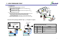
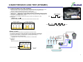
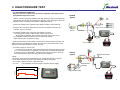
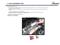
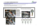
NCT-1500 Common Rail Tester Quick Manual
1. GENERAL
This Tester has been developed to diagnose efficiently and accurately for diesel vehicles with common rail system.
1-1. Criteria of diagnosis using Common Rail Tester
Impossible to start engine or engine stall while driving
※ It would be recommended performing Power Balance Test by Scanners(for Bosch system) or by disconnecting injector's connecter one by one(for Delphi system),
if vehicle has problem beside the above symptoms such as engine vibration or emission of black/white smoke while engine idle.
The problem may be due to differences of the injected amount in each injector.
1-2. Notice
A CRDi system has been constructed using precision-made components.
If an extremely small foreign particle enters the system during service, it may cause sticking or clogging of injectors.
Therefore, be sure to eliminate any dust or contaminated deposits on or around the engine and fuel lines during service.
2. COMPONENTS
1
16
9
2
3
18
10
11
M12mm
4
M14mm
5
20
12
13
6
21
22
7
15
8
14
23
17
17
19
1. Tool Case
2. Plug (for Delphi)
3. Plug (for Bosch)
4. Flask & Holder
5. Injector return hose adapter
6. Injector return hose plug
7. Flushing Tube
8. Dust Cap
9. High pressure gauge set
10. Adapter connector (for Delphi old)
11. Adapter connector (for Delphi new)
12. Adapter connector (for Bosch)
13. Vacuum Gauge
14. Low pressure gauge
15. Gauge connection tube
16. Connection Adapter
17. Connection adapter with hose
18. Fuel Filter Plug
19. Dummy Resister
20. Dummy Injector
21. Compression Gauge
22. Block Tube
23. User's Manual
1
1. LOW PRESSURE TEST
3. DIAGNOSTIC
4-1. DIAGNOSIS PROCEDURE ACCORDING TO SYMPTOM
1) When the engine is not able to start
① Low Pressure Line Test → ② Injector Back Leak Test (Static Test) →
③ High Pressure Line Test
2) When the engine is able to start
① Low Pressure Line Test → ② Injector Back Leak Test (Dynamic Test) →
③ High Pressure Line Test
4-2. LOW PRESSURE FUEL LINE TEST
1) Remove fuel hose from fuel filter and connect low pressure gauge (NCT-1051) or
vacuum gauge (NCT-1050) according to engine system as shown.
* Additional parts needed: tube for gauge connection (NCT-1052),
Connection adapter with hose (NCT-1054), connection adapter (NCT-1053)
Fuel Filter Plug (NCT-1055)
2) Start the engine and keep idle approximately 5seconds, then turn of the engine.
Internal suction pump type (Bosch Type Ⅰ) (A engine / U engine)
Vacuum Gauge
ⓑ
ⓑ Vacuum Gauge
ⓒ Test Tube Assay
ⓓ Connection
Adapter
ⓓ
ⓒ
ⓑ
ⓓ
ⓒ
Internal suction pump type (Bosch Type)
CASE
VACUUM
JUDGMENT
1
10~20 cmHg
System normal (good condition)
2
20~60 cmHg
Filter or fuel line clogging (pump in good
condition)
3
0~10 cmHg
Air leak in to the system or Suction pump
damage
2
1. LOW PRESSURE TEST
Electric pump type (Bosch Type II)
Electric pump type (BOSCH Type Ⅱ)
Pressure Gauge
ⓐ
ⓒ
ⓓ
ⓔ
ⓕ
ⓐ
Low Pressure Gauge
Test Tube Assay
Connection Adapter
Connection Adapter with Hose
Hose Clamp
EURO-Ⅲ model
CA
SE
ⓔ
ⓒ
ⓓ
ⓕ
PRESSURE (bar)
JUDGMENT
1
1.5~3.5 kg/㎠
System normal
2
0 ~1.5 kg/㎠
Fuel Filter (or fuel line / strainer) clogging
3
no pressure
Abnormal function of fuel pump
EURO-Ⅳ model
CA
SE
Fuel pump
(Electric)
PRESSURE (bar)
JUDGMENT
1
2.5 ~ 5 kg/㎠
System normal
2
0.5~2.0 kg/㎠
Filter or fuel line clogging (pump in good
condition)
3
no pressure
Abnormal function of fuel pump
Internal suction pump type (Delphi)
ⓑ
ⓒ
ⓓⓓ
ⓖ ⓖ
Internal suction pump type ( Delphi)
CASE
VACUUM
JUDGMENT
1
10~20 cmHg
System normal (good condition)
2
20~60 cmHg
Filter or fuel line clogging (pump in good
condition)
3
0~10 cmHg
Air leak in to the system or Suction pump
damage
3
1. LOW PRESSURE TEST
4-3. INJECTOR BACK LEAK TEST (STATIC)
1) Remove the return hose from each injector and Install injector return hose adapter
visible tubes and connect the visible tube's end to the flasks
2) Disconnect "A" point on the fuel return hose in below photograph and block the fuel return hose
in the direction of the high pressure pump with injector return hose plug
3) Connect the adapter connector to rail pressure sensor and connect high pressure gauge as shown.
4) Disconnect the injector connectors to prevent its operating.
Delphi, Bosch TypeⅠ
5) for “ A” engine Remove the Inlet Metering Valve connector to allow fuel feeding to high pressure line.
Bosch Type Ⅱ
6) Disconnect the Pressure Control Valve connector and connect the power line on High Pressure
Gauge to the Pressure Regulator Valve, and then connect High Pressure Gauge
's lead to battery so that pressure control valve will block fuel return from rail.
7) Crank the engine once for 5~6 seconds
※ Cranking engine about 10second build pressure, test again if pressure are
not reach to maximum pressure.
※ Cranking RPM must exceed 200 RPM.
※ Perform the test under 30℃ with coolant temperature
(If the fuel pressure test performed over30℃, the fuel pressure indicated
may be different according to fuel viscosity change.).
8) Read the pressure from high pressure gauge and measure the
amount of fuel contained at each visible tube
9) Judgment
Injector Back Leak
CASE
PRESSRUE
BACK LEAK
JUDGEMENT
1
1000~1800
(above 1000)
0~200mm
(below 200)
Normal
2
0~1000
(below 1000)
200~400
(above 200)
Faulty injector
(excessive back leak)
3
0~1000
(below 1000)
0~200
(below 200)
HP Pump
(Insufficient pressure)
SERVICE SPEC
High pressure : Above 700 bar ( with normal Back Leak condition)
※ Exceeding back leak can cause insufficient high pressure
Back Leak
: Less than 3.5 times than minimum amount injector
CHECK POINT (if test is failed )
- Fuel Leak (rail plug or pipes connection)
- PRV (leakage or damaged)
- Fuel line ( clogging filter )
- HP pump (leakage or damaged)
4
3
2
1
Adapters for
rail pressure sensor
High pressure sensor
Dummy Resister
Sensor abnormal
Low
pressure
Normal
High pressure Pump
4
2.INJECTOR BACK LEAK TEST (DYNAMIC)
4- 4. INJECTOR BACK LEAK TEST (DYNAMIC)
1) Remove the return hose from each injector and Install injector return hose adapter (NCT-1032),
visible tubes (NCT-1032), flasks (NCT-1030) and injector return hose plug (NCT-1033)
referring to Injector back leak test (STATIC) in previous page.
2) Conduct the high pressure leak test referring to following explanation.
BOSCH Type Ⅰ,Ⅱ,Ⅲ : D3EA(1.5D-ENG), D4EA(2.0D-ENG), D4FA(U-ENG), D4CB(2.5A-ENG)
3) Start engine → 3 minutes at idle → accelerate engine up to 2500 rpm and keep the 2500rpm for
2 minutes →Stop Engine after 2 minutes
4) When the test is completed, measure the amount of fuel in each flask (NCT-1030).
5) Judgments
30sec / 3000rpm
Start
1min
stop
BOSCH Type Ⅰ,Ⅱ,Ⅲ
Replace the injector which is shown more 3 times than the minimum value.
#2 Injector abnormal
Normal condition
Start
2min
Stop
Idle
acceleration
1
2
3
1
4
2
3
4
DELPHI : J3 (2.9L)
3) Connect the Hi-Scan and select the 'High Pressure Leak Test' mode.
4) Conduct the 'High Pressure Leak Test' untill the Hi-Scan finish the test automatically.
or manualy : Start engine → 2minutes at idle → 3 times acceleration →Stop Engine
5) For the accuracy of the test, perform the test more than twice and select
the largest amount as a measured value.
※ The flasks (NCT-1030) should be empty before the 2nd test started.
6) Judgments
DELPHI
Replace the injector which indicates exceeds 25cc.
Service Limit 25cc
1
2
3
4
Abnormal
injector
5
3. HIGH PRESSURE TEST
4-5. HIGH PRESSURE PUMP TEST
Purpose of the test : Inspection for mechanical capability of the High pressure
pump (Maximum pressure check)
Method : Check the pumping capability of the high pressure pump by actuating pump
after blocking rail's outlets using the plug and regulator. Plug : Blocking the rail circuit
Regulator Valve : Preventing over pressure of high pressure line
BOSCH
System
Rail
Plug
1) Clean the regulator valve, regulator valve adaptor and plugs with diesel fuel.
2) Remove all 4 fuel injector pipes from the common rail and disconnect the rail
pressure sensor's connector.
High pressure sensor
Dummy
Resister
3) Install the regulator valve, plugs dust caps adapter connector
and High pressure gauge to the common rail securely as shown.
※ Be sure that the regulator valve and the plugs (NCT-1020 or NCT-1021)
have installed securely so that there will not be any fuel leakage.
Delphi, Bosch TypeⅠ(A engine U engine)
4) Disconnect Pressure Control Valve connector and connect the PRV connector and
battery lead wire to the battery for the test. And then turn on the power switch so that
pressure control valve will block fuel return from rail.
5) Crank the engine for 5-6 seconds.
For the accuracy of the test, perform the test twice and select the higher pressure
one as a measured value. 6) Judgment If the fuel pressure indicated on the gauge
is within the range of specification, the high pressure pump is normal. But if not
check the below items before the High pressure pump replaced.
High pressure Pump
DELPHI
System
NOTE :
The buzzer will be ringing and changed the color of bulb after 5minuts of each test
for the safety reasons ( to prevent over heating and battery discharged )
- 0~5 minutes : Maximum currant supply to the PRV
- 5 or over
: Low (regulated) currant are supply to the PRV (buzzer ringing)
Pressure Valve
Connector
High pressure Pump
Current
ON
Off
High pressure sensor
0
5
10
Minute
6
3. HIGH PRESSURE TEST
4-5. HIGH PRESSURE PUMP TEST
b. If fuel pressure is lower than specification, test it again when coolant temperature is below 30℃. The pump is in normal condition if
the pressure restores to normal range.
c. In case of the system in which pressure control valve implemented, check the valve condition & internal leak and replace them if
necessary.
* Refer to '4-6 pressure control valve test' procedure
If fuel pressure indicated on the gauge is lower than specification there may be a problem in the rail pressure sensor
or its circuit even fuel flows out from the regulator valve (NCT-1020)
Specification of high pressure of common rail :
BOSCH System : 1000~1500 bars
DELPHI System : 1050~1600 bars
7
4. PRESSURE CONTROL VALVE TEST
4-6. PRESSURE CONTROL VALVE TEST
1) Remove fuel return connector from PCV upper.
2) Remove fuel return hose from PCV lower.
3) Disconnect Pressure Control Valve connector and connect
the High Pressure Gauge(NCT-1040) to the
Pressure Control Valve, and then connect the High Pressure
Gauge(NCT-1040)'s lead to battery so that
pressure control valve will block fuel return from rail.
4) Put fuel return pipes to flasks(NCT-1030).
5) Crank the engine for 5 seconds.
6) Check fuel return amount.
※ Service Limit : Less than 10cc/ 5second
(Fuel pressure must over 1000 bars)
BOSCH
Rail Plug
High pressure sensor
Dummy
Resister
High pressure Pump
Fuel pipe end
Air gun nozzle
1) Before connecting the fuel pipes to the engine, be sure
that all the pipe outlet surfaces, inner passages, and especially fuel pipe
fitting nuts are clean.
Clean using air gun if necessary.
2) Assemble all fuel pipes except the fuel pipe fitting nuts of injector side.
3) Temporarily tighten the fuel pipe fitting nuts to injectors by hand after
aligning the nuts to the injectors.
4) To prevent contamination on engine room, wrap up around the injector pipe
using paper towel or shop rag as shown.
5) Crank the engine 2 to 3 times for 5 to 6 seconds to flow out the fuel
contamination from injector connection area.
6) Tighten the nuts with specified torque using special tool.
7) Erase the DTC code by Scanner.
Cleaning by air
gun
Loosen the nuts
Tighten the nuts
Paper towel
Injector
8
5. CYLINDER COMPRESSION TEST
Cylinder compression comparison Test
- Purpose of this test is to perform the compression comparison test for each cylinder to determine the abnormal cylinders. You can
perform the test quickly and easily.
1. Remove the injectors from the engine and install the dummy injectors to prevent oil spill in to the cylinders during test.
2. Select the correct groove for engine type to install the dummy injectors
3. Using the quick coupling on the dummy injectors you can do the compression test easily and fast.
※ Select the correct groove for engine type to install the dummy
injectors.
※ Using the quick coupling on the dummy injectors
you can do the compression test easily and fast.
Groove
1
2
3
4
9