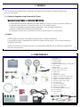
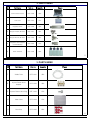
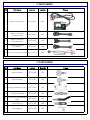
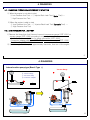
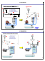
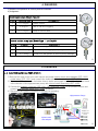
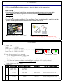
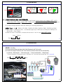
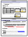
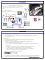
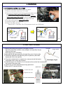
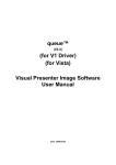
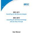
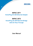
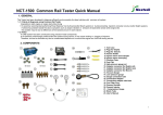
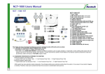
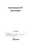
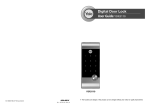
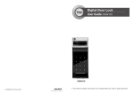
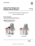
1
Common Rail Tester
FOREWARD
This manual is intended for use by service technicians to help provide efficient and correct service on CRDi
vehicles using Common Rail Tester.
To ensure customer satisfaction with Nextech product, it is essential quick and accurate service operation
as well as reasonable price.
Consequently, it is important that the service personnel fully understand the contents of this manual, which
should be kept within reach for future reference.
All information in this manual including photographs, drawings, and specifications is current
at the time of publication.
Nextech reserves the right to make any changes to the design or to make additional improvements in this
manual.
No part of this manual hereon may be reproduced or used in any form of by any means – graphic,
electronic, or mechanical, including photocopying, recording, taping, or information storage and retrieval
systems – without written permission of the publisher.
DEC ,2005, Printed in Korea
1
CONTENTS
1. GENERAL
2. COMPONENTS
3. PARTS INDEX
4. DIGNOSIS
4-1. DIAGNOSIS PROCEDURE ACCORDING TO SYMPTOM
4-2. LOW PRESSURE FUEL LINE TEST
4-3. INJECTOR BACK LEAK TEST (STATIC)
4-4. INJECTOR BACK LEAK TEST (DYNAMIC)
4-5. HIGH PRESSURE PUMP TEST
4-6. PRESSURE CONTROL VALVE TEST
5. FUEL LINE FLUSHING
6. DIAGNOSIS CHECK SHEET
2
1. GENERAL
This Tester has been developed to diagnose efficiently and accurately for diesel vehicles with
common rail system.
1-1. Criteria of diagnosis using Commom Rail Tester
Impossible to start engine or engine stall while driving
※ It would be recommended performing Power Balance Test by Hi-Scan (for Bosch system) or
by disconnecting injector's connecter one by one (for Delphi system),
if vehicle has problem beside the above symptoms such as engine vibration or
emission of black/white smoke while engine idle.
The problem may be due to differences of the injected amount in each injector.
1-2. Notice
A CRDi system has been constructed using precision-made components.
If an extremely small foreign particle enters the system during service, it may cause sticking or
clogging of injectors.
Therefore, be sure to eliminate any dust or contaminated deposits on or around the engine and
fuel lines during service.
3
2. COMPONNENTS
18
17
1
20
4
21
3
2
22
5
23
19
M12mm
8
7
9
11
12
6
1. Tool Case
2. Regulator Valve
3. Plug(for Delphi)
4. Plug(for Bosch)
5. Regulator Valve Adapter(for SM model)
6. Flask & Holder
7. Visible Tube
8. Injector return hose adapter
9. Injector return hose plug
10. Clean Case
11. Dust Cap
12. High pressure gauge
13. Adapter connector (for Delphi old)
14. Adapter connector(for Delphi new)
15. Adapter connector(for Bosch)
16. Pressure Control Valve cable
17. Vacuum Gauge
18. Low pressure gauge
19. Gauge connection tube
20. Connection Adapter
21. Connection adapter with hose
22. Fuel Filter Plug
23. User's Manual
13
14
15
10
16
4
3. PARTS INDEX
NO
Part Name
Part no.
Quantity
Common Rail Tester
CRT-1000
1SET
1
Tool Case
CRT-1010
1EA
2
Regulator Valve
CRT-1020
1SET
3
Plug(for Delphi) M14mm
CRT-1021
3EA
4
Plug(for Bosch) M12mm
CRT-1022
3EA
5
Regulator Valve Adapter
(for SM Model))
CRT-1023
1EA
6
Flask & Holder
CRT-1030
1SET
Figure
5
3. PARTS INDEX
NO
Part Name
Part no.
Quantity
7
Visible Tube
CRT-1031
4EA
8
Injector Return Hose
Adapter
CRT-1032
4EA
9
Injector Return Hose Plug
CRT-1033
1EA
10
Clean Case
CRT-1034
1EA
11
Dust Cap
CRT-1035
8EA
Figure
6
3. PARTS INDEX
NO
Part Name
Part no.
Quantity
12
High Pressure Gauge
CRT-1040
1SET
13
Adapter Connector
(for Delphi Old)
CRT-1041
1EA
14
Adapter Connector
(for Delphi New)
CRT-1042
1EA
15
Adapter Connector
(for Bosch)
CRT-1043
1EA
16 Pressure Control Valve Cable CRT-1044
Figure
1SET
7
3. PARTS INDEX
NO
Part Name
Part no.
Quantity
17
Vacuum Gauge
CRT-1050
1EA
18
Pressure Gauge
CRT-1051
1EA
19
Gauge Connection Tube
CRT-1052
1EA
20
Connection Adapter
CRT-1053
1EA
21
Connection Adapter With
Hose
CRT-1054
1EA
22
Fuel Filter Plug
CRT-1055
1EA
23
User's Manual
CRT-1055
1EA
Figure
8
4. DIAGNOSIS
4-1. DIAGNOSIS PROCEDURE ACCORDING TO SYMPTOM
1) When the engine is not able to start
① Low Pressure Line Test → ② Injector Back Leak Test (Static Test) →
③ High Pressure Line Test
2) When the engine is able to start
① Low Pressure Line Test → ② Injector Back Leak Test (Dynamic Test) →
③ High Pressure Line Test
4-2. LOW PRESSURE FUEL LINE TEST
1) Remove fuel hose from fuel filter and connect low pressure gauge (CRT-1051) or
vacumn gauge (CRT-1050) according to engine system as shown.
* Additional parts needed: tube for gauge connection (CRT-1052),
Connection adapter with hose (CRT-1054), connection adapter (CRT-1053)
Fuel Filter Plug (CRT-1055)
2) Start the engine and keep idle approxmately 5seconds, then turn of the engine.
9
4. DIAGNOSIS
Internal suction pump type (Bosch Type Ⅰ)
Vacuum Gauge
ⓑ
ⓑ Vacuum Gauge
ⓒ Test Tube Assay
ⓓ Connection Adapter
ⓒ
ⓓ
ⓑ
ⓓ
ⓒ
10
4. DIAGNOSIS
Electric pump type (Bosch Type Ⅱ)
ⓐ
Pressure Gauge
Pressure Gauge
ⓐ Low Pressure Gauge
ⓒ Test Tube Assay
ⓓ Connection Adapter
ⓔ Connection Adapter with
Hose
ⓔ
ⓕ Hose Clamp
ⓒ
ⓓ
ⓕ
Fuel pump
(Electric)
11
4. DIAGNOSIS
Internal suction pump type (Delphi)
ⓑ
ⓑ
ⓑ Vacuum Gauge
ⓒ Test Tube Assay
ⓓ Connection Adapter
ⓖ Fuel Filter Plug
ⓒ
ⓓⓓ
ⓖ ⓖ
12
4. DIAGNOSIS
3) Read the fuel pressure or suction pressure indicated.
4) Judgement
Electric pump type (Bosch Type Ⅱ)
CASE
PRESSURE (bar)
1
1.5~3 kg/㎠
2
4~6 kg/㎠
3
0~1.5 kg/㎠
JUDGEMENT
System normal
Filter or fuel line clogging
Pump or fuel line leak
Internal suction pump type (Bosch Type Ⅰ and Delphi)
CASE
VACUUM
JUDGEMENT
1
8~19 cmHg
System normal (good condition)
2
20~60 cmHg
Filter or fuel line clogging (pump in good condition)
3
0~7 cmHg
Air leak in to the system or Suction pump damage
13
4. DIAGNOSIS
4-3. INJECTOR BACK LEAK TEST (STATIC)
1) Remove the return hose from each injector and Install injector return hose adapter (CRT-1032),
visible tubes (CRT-1031) and connect the visible tube's end to the flasks (CRT-1030).
2) Disconnect "A" point on the fuel return hose in below photograph and block the fuel return hose
in the direction of the high pressure pump with injector return hose plug (CRT-1033).
3) Connect the adapter connector (CRT-1041,CRT-1042,CRT-1043) to rail pressure sensor and
connect high pressure gauge (CRT-1040) as shown.
4) Disconnect the injector connectors to prevent its operating.
High-pressure Gauge
"A"
Injector return
hose plug
Adapters for
rail pressure
sensor
Injector return
hose adapter
14
4. DIAGNOSIS
Delphi, Bosch TypeⅠ
5) Remove the Inlet Metering Valve connector to allow fuel feeding to high pressure line.
Bosch Type Ⅱ
5) Disconnect the Pressure Control Valve connector and connect the pressure control valve cable
(CRT-1044) to the Pressure Regulator Valve, and then connect pressure control valve cable
(CRT-1044)'s lead to battery so that pressure control valve will block fuel return from rail.
Bosch Type Ⅲ
5) Perform No. 5) procedure both Bosch TypeⅠand Bosch Type Ⅱ so that fuel will be supplied to the high
pressure line and pressure control valve will block fuel return from the rail.
PCV
Pressure control
valve cable
IMV connector
● Delphi, Bosch TypeⅠ,Bosch Type Ⅲ
● Bosch Type Ⅱ, Bosch Type Ⅲ
※ Notice : Do not supply the battery power over
5 minutes. It may cause to damage PCV.
15
4. DIAGNOSIS
* Engine Type
Delphi
Bosch TypeⅠ
Bosch Type Ⅱ
Bosch Type Ⅲ
: J3(2.9L)
: D4CB(2.5A-ENG)
: D3EA(1.5D-ENG), D4EA(2.0D-ENG),
: D4FA(1.5U-ENG)
Sensor abnormalLow pressure
Normal
6) Crank the engine once for 5 seconds.
※ Do not exceed the 5seconds in any case.
※ Cranking RPM must exceed 200 RPM.
※ Perform the test under 30℃ with coolant temperature (If the fuel pressure test performed over
30℃, the fuel pressure indicated may be diffrent accoding to fuel viscosity change.).
7) Read the pressure from high pressure gauge (CRT-1040) and measure the amount of fuel contained
at each visible tube (CRT-1031).
8) Judgement
CASE
PRESSRUE(bar)
INJECTOR BACK LEAK
JUDGEMENT
FACTOR TO BE CHECKED
1
1000~1800
(above 1000)
0~200mm
(below 200)
Normal
2
0~1000
(below 1000)
200~400
(above 200)
Faulty injector
(excessive back leak)
Replace injector if there is only
excessive back leak (over 200mm).
3
0~1000
(below 1000)
0~200
(below 200)
HP Pump
(Insufficient pressure)
Conduct the high pressure pump
test
16
4. DIAGNOSIS
Limit: 200mm
Sensor abnormal
Low pressure
Normal
4- 4. INJECTOR BACK LEAK TEST (DYNAMIC)
1) Remove the return hose from each injector and Install injector return hose adapter (CRT-1032),
visible tubes (CRT-1031), flasks (CRT-1030) and injector return hose plug (CRT-1033) referring to
Injetor back leak test (STATIC) in previous page.
2) Conduct the high pressure leak test refering to following explanation.
BOSCH Type Ⅰ,Ⅱ,Ⅲ : D3EA(1.5D-ENG), D4EA(2.0D-ENG), D4FA(U-ENG), D4CB(2.5A-ENG)
3) Start engine → 1minute at idle → accelerate engine up to 3000 rpm and keep the 3000rpm for
30seconds →Stop Engine
4) When the test is completed, measure the amount of fuel in each flask (CRT-1030).
30sec / 3000rpm
Start 1min
sto
17
4. DIAGNOSIS
DELPHI : J3 (2.9L)
3) Connect the Hi-Scan and select the 'High Pressure Leak Test' mode.
4) Conduct the 'High Pressure Leak Test' untill the Hi-Scan finish the test automatically.
or manualy : Start engine → 2minutes at idle → 3 times acceleration →Stop Engine
※One acceleration: Accelerate up to 3800rpm for 2 seconds and keep idle for 2 seconds.
Start
2min
Stop
Idle
acceleratio
18
4. DIAGNOSIS
5) For the accuracy of the test, perform the test more than twice and select
the largest amount as a measured value.
※ The flasks (CRT-1030) should be empty before the 2nd test started.
6) Judgement
BOSCH Type Ⅰ,Ⅱ,Ⅲ
Replace the injector which is shown more 3 times than the minimum value.
● Example
Injectors
Quantity back leaked
Results
Cylinder 1
30
Cylinder 2
61
Faulty injector
Cylinder 3
20
Minimum value
Cylinder 4
30
Normal condition
1
2
3
44
#2 Injector abnormal
1
2
3
4
DELPHI
Replace the injector which indicates exceeds 25cc.
Service Limit 25cc
1
2
3
4
Abnormal
injector
19
4. DIAGNOSIS
4-5. HIGH PRESSURE PUMP TEST
1) Clean the regulator valve (CRT-1020), regulator valve adaptor (CRT-1023) and plugs (CRT-1021
or CRT-1022) with diesel fuel.
2) Remove all 4 fuel injector pipes from the common rail and disconnect the rail pressure
sensor's connector.
3) Install the regulator valve (CRT-1020), plugs (CRT-1021 or CRT-1022), dust caps (CRT-1035),
adapter connector (CRT-1041, CRT-1042,CRT-1043) and High pressure gauge (CRT-1040)
to the common rail securely as shown.
※ Use regulator valve adaptor (CRT-1023) for Santafe(SM) model.
※ Be sure that the regulator valve (CRT-1020) and the plugs (CRT-1021 or CRT-1022) have
installed securely so that there will not be any fuel leakage.
Delphi, Bosch TypeⅠ
4) Disconnect the IMV connector from the high pressure pump.
Bosch Type Ⅱ
4) Disconnect Pressure Control Valve connector and connect the pressure control valve cable
(CRT-1044) to the Pressure Regulator Valve, and then connect pressure control valve cable
(CRT-1044)'s lead to battery so that pressure control valve will block fuel return from rail.
Bosch Type Ⅲ
4) Perform No. 4) procedure both Bosch TypeⅠand Bosch Type Ⅱ so that fuel will be supplied to
the high pressure line and pressure control valve will block fuel return from the rail.
20
4. DIAGNOSIS
Purpose of the test : Inspection for mechanical capability of the High
pressure pump (Maximum pressure check)
Method : Check the pumping capability of the high pressure pump by
actuating pump after blocking rail's outlets using the plug and
regulator.
Plug : Blocking the rail circuit
Regulator Valve : Preventing over pressure of high pressure line
Regulator
valve
Regulator valve
adapter for
Santafe
Adapters for
rail pressure sensor
21
4. DIAGNOSIS
5) Crank the engine for 5-6 seconds.
For the accuracy of the test, perform the test twice and select the higher pressure one
as a measured value.
6) Judgement
If the fuel pressure indicated on the gauge is within the range of specification,
the high pressure pump is normal.
But if not, check the below items before the High pressure pump replaced.
a. Check the plug or regulator valve if it leaks.
b. If fuel pressure is lower than specification, test it again when coolant temperature is
below 30℃.
The pump is in normal condition if the pressure restores to normal range.
c. In case of the system in which pressure control valve implemented,
check the valve condition & internal leak and replace them if necessary.
* Refer to '4-6 pressure control valve test' procedure
Specification of high pressure of common rail :
BOSCH System : 1000~1500 bars
DELPHI System : 1050~1600 bars
If fuel pressure indicated on the gauge is lower than specification there may be a problem in
the rail pressure sensor or its circuit even fuel flows out from the regulator valve (CRT-1020).
22
4. DIAGNOSIS
4-6. PRESSURE CONTROL VALVE TEST
1) Remove fuel return connector from PCV upper.
2) Remove fuel return hose from PCV lower.
3) Disconnect Pressure Control Valve connector and connect
the pressure control valve cable (CRT-1044) to the
Pressure Control Valve, and then connect the pressure
control valve cable (CRT-1044)'s lead to battery so that
pressure control valve will block fuel return from rail.
4) Put fuel return pipes to flasks(CRT-1030).
5) Crank the engine for 5 seconds.
6) Check fuel return amount.
※ Service Limit : Less than 10cc (Fuel pressure must over 1000 bars)
Fuel return
Fuel return connector
PCV
Return Hose
Leaked fuel
Limit ( 10cc/5sec)
Pressure control
valve cable
23
5. FUEL LINE FLUSHING
1) Before connecting the fuel pipes to the engine, be sure
Fuel pipe
Air gun nozzle
that all the pipe outlet surfaces, inner passages, and especially fuel pipe
fitting nuts are clean.
Clean using air gun if necessary.
2) Assemble all fuel pipes except the fuel pipe fitting nuts of injector side.
3) Temporarily tighten the fuel pipe fitting nuts to injectors by hand after
aligning the nuts to the injectors.
4) To prevent contamination on engine room, wrap up around the injector pipe
Cleaning by air gun
using paper towel or shop rag as shown.
5) Crank the engine 2 to 3 times for 5 to 6 seconds to flow out the fuel contamination
from injector connection area.
6) Tighten the nuts with specified torque using special tool.
7) Erase the DTC code by Hi-Scan.
Special tool
Loosen the nuts
Tighten the nuts
Fuel with contaminations
Injecto
Paper towel
24
6. DIAGNOSIS CHECK SHEET
Model :
VIN :
Test items
NO
1
Milage :
Value measured
(
(
Low Pressure Fuel Line Test
Rail pressure
Static
2
3
) bars
(Good, Failure)
(Good, Failure)
# 1 Cylinder (
) Cm
(Good, Failure)
# 2 Cylinder (
Amount of
fuel
in visible tube # 3 Cylinder (
) Cm
(Good, Failure)
) Cm
(Good, Failure)
# 4 Cylinder (
) Cm
(Good, Failure)
# 1 Cylinder (
) Cm
(Good, Failure)
# 2 Cylinder (
Amount of
fuel
in visible tube # 3 Cylinder (
) Cm
(Good, Failure)
) Cm
(Good, Failure)
# 4 Cylinder (
) Cm
(Good, Failure)
Injector Back
Leak Test
Dynamic
(
) Kg/㎠
) CmHg
Result
Fuel Pressure Test
(
) bars
(Good, Failure)
25
Tool supplier : Nextech Co., Ltd.
Contact Point : Mr. Alex Lim
Tel : +82-2-3140-1489 or 1443
Fax : +82-2-3140-1449
E-mail : [email protected]
26
QUALITY ASSURANCE
Name of products: Commom Rail Tester
We hereby certify that the above product is guaranteed by our quality assurance policy and
procedures listed below.
Subject of assurance: All components contained in the Common Rail Tester as supplied to all Nextech
distributors and dealers by Nextech Co., Ltd.
Parts Guarantee
: Quality and Durability of each component.
Guarantee Period
:1 Years from the date of purchase.
Nextech Co., Ltd.
President:
27
Seoul Korea
Printing: SEP. 2005
Publication No.: OSTS-20050901-E
Printed in Korea