1
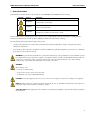
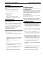
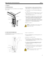
Thermo Scientific
MR05 Series Undercounter
Laboratory Refrigerators
Installation and Operation Manual
324019H01 Rev. A
Table of Contents
1. Safety Precautions ..................................................................................................... 1
2. Specifications ............................................................................................................ 2
2.1. General specifications ......................................................................................... 2
2.2. Performance specifications .................................................................................. 2
2.3. Electrical specifications ....................................................................................... 2
2.4. Refrigeration specifications ................................................................................. 2
3. Introduction ............................................................................................................... 3
4. Inspection for Damage .............................................................................................. 3
5. Installation Instruction ............................................................................................. 3
6. Operating Instructions .............................................................................................. 3
6.1. Temperature Control ........................................................................................... 3
6.2. Defrosting ............................................................................................................ 3
7. Maintenance Instructions ......................................................................................... 3
8. Service ........................................................................................................................ 4
8.1. Hinge Adjustment ................................................................................................ 4
8.2. Latch and Strike Adjustment ............................................................................... 4
8.3. Door gasket replacement ..................................................................................... 5
8.4. Wiring Diagram ................................................................................................... 5
8.5. Controller Operations .......................................................................................... 6
8.6. Troubleshooting ................................................................................................... 9
8.7. Replacement parts ............................................................................................. 12
9. Warranty Statement ................................................................................................ 13
MR05 Undercounter Laboratory Refrigerators
Safety Precautions
1 Safety Precautions
In this manual and on labels attached to this product, the words WARNING and CAUTION mean the following:
SYMBOL
SIGNAL
MEANING
WARNING
Indicates an imminently hazardous situation, which, if not avoided, could
result in death or serious injury.
CAUTION
Indicates an imminently hazardous situation, which, if not avoided, may result
in minor or moderate injury.
WARNING
Indicates hazards associated with the use of electrical energy wherein, if
precautions are not taken, can cause injury or death.
Before installing, using or maintaining this product, please be sure to read this manual and product warning labels carefully. Failure to
follow these instructions may cause this product to malfunction, which could result in injury or damage.
The following important safety precautions apply to this product:
•
Use this product only in the way described in the product literature and in this manual. Before using it, verify that this product is
suitable for its intended use.
•
Do not modify system components, especially the controller. Use OEM exact replacement equipment or parts. Before use, confirm that
the product has not been altered in any way.
WARNING For personal safety and trouble-free operation, this unit must be properly grounded before it is used. Failure to ground
the equipment may cause personal injury or damage to the equipment. Always conform to the National Electrical Code and local
codes. Do not connect unit to already overloaded power lines. Disconnect the unit from all power sources before cleaning,
troubleshooting, or performing other maintenance on the product or its controls.
WARNING
These refrigerators are
• not for use as a medical device
• not approved for storage of blood or blood products
• not intended for the storage of flammable materials
CAUTION Connect the equipment to the correct power source. Incorrect voltage can result in severe damage to the equipment.
NOTE This unit is designed to operate in areas that are heated to 60° F (15.6° C). Installation in unheated areas may require a low
temperature compressor protection kit for satisfactory operation.
Safety Disclaimer: If the equipment is used in a manner not specified by the manufacturer, protection afforded by the equipment
may be impaired.
1
MR05 Undercounter Laboratory Refrigerators
Specifications
2 Specifications
2.1 General specifications
Model Series
MR05
Model Style
Undercounter
Capacity
5.4 cu ft (153 Liters)
Exterior Dimensions:
Height (inches)
34 5/8"
Width (inches)
24"
Depth (inches)
24 1/8" Cabinet Depth
2.2 Performance specifications
Operating Temperature Range
+2°C to +10°C
Preset Temperature Setpoint
+4°C
2.3 Electrical specifications
Power Supply
115V, 60Hz, 1 phase
Full load amperes
8.2A
Minimum circuit Breaker Capacity
15 Amps
2.4 Refrigeration specifications
Refrigerant
R134a
Charge quantity
6 oz
2.5 Environmental Operating Conditions
Pollution Degree
2
Installation Category
II
Maximum Altitude
2000m Mean Sea Level
Humidity
80% maximum, non condensing
Temperature
15°C to 32°C
Product Usage
Indoor use only
2
MR05 Undercounter Laboratory Refrigerators
3 Introduction
This manual provides installation, operation and maintenance
instructions for MR05 General purpose laboratory refrigerator
models.
The control system, standard on all models, includes:
Installation, Operation and Maintenance
7. Do not install temperature sensing cables using the front door
gasket. Instead, use the rear access ports.
6 Operating Instructions
6.1 Temperature Control
Other standard features include:
The temperature control system is preset by the factory to maintain
a cabinet temperature of 4°C. Adjustment of operating values are
possible, but may change unit performance. Consult a qualified
service technician if you have questions about settings.
•
Keyed door locks
6.2 Automatic Defrost
•
CFC-free refrigerant
•
CFC-free foamed in-place urethane insulation
•
Quiet, hermetically sealed refrigeration compressors.
•
Preset temperature setpoint (+4°C).
•
Digital temperature display with 1°C resolution.
The defrosting process on all models is primarily accomplished by
air circulated during off-cycle periods.
4 Inspection for Damage
Under normal conditions, the temperature warm-up during defrost is
virtually unnoticeable. However, an occasional 2°C warm-up is
possible if usage is heavy and ambient conditions are extreme.
At delivery, examine the exterior for physical damage while the
carrier’s representative is present.
7 Maintenance Instructions
If there is no exterior damage, unpack and inspect the equipment
within five days of delivery. If you find any damage, keep the
packing materials and immediately report the damage to the carrier.
Do not return goods without written authorization. When
submitting a claim for shipping damage, request that the carrier
inspect the shipping container and equipment.
5 Installation Instruction
This product is a complete packaged unit ready to operate when
plugged into an electrical source. Read all the instructions before
proceeding with installation.
1. The cabinet will pass through a standard 30” door opening.
2. Move the cabinet into the desired location. Make sure the
bottom of the cabinet is evenly supported. Thin shims under
the points of rest can be used to equalize the distribution of
weight. If the cabinet sets on an uneven floor, a slight rocking or
vibration might result when the condensing unit is set in
operation.
3. Make certain the cabinet is located so the front grill is
unobstructed.
4. The unit is shipped in ready to operate condition. Adjustment
of operating temperatures or setpoint is not necessary and may
adversely effect unit performance.
5. Use of electrical supply, other than that specified on the serial
plate will cause permanent damage to the product.
6. Operate the unit for several hours to allow the cabinet to reach
normal operating temperatures before storing product.
1. The cabinet interior should be cleaned frequently. Any spilled
liquid should be wiped off immediately. A mild detergent and
lukewarm water or a solution of bicarbonate of soda (1
tablespoon per gallon of water) is recommended for cleaning
the interior and exterior of the cabinet. All surfaces should be
rinsed and thoroughly dried.
2. Shelves and/or drawers should be removed from the cabinet
and thoroughly scrubbed. Clean door gasket periodically with
water.
3. The unit cooler fan operates continuously when the door is
closed and requires no lubrication. These models require no
manual defrosting. The cooling coil automatically defrosts
when the condensing unit is on the off cycle.
4. The condensing unit needs no oil or other lubrication. The
finned condenser can become clogged with lint or dust. The
openings between the fins should be kept clean. A vacuum
cleaner or small test tube brush works well for this purpose.
This should be accomplished on an annual basis. Failure to
keep the condenser fins free of dirt and lint will hamper
operation and may damage the refrigeration system.
5. Annual inspection of the mechanical refrigeration equipment
by a qualified service provider or factory direct technician is
recommended.
6. The refrigeration system is charged with refrigerant. If the
system is opened for any reason, extreme care should be taken
to prevent the entry of moisture-bearing air. A new drier should
be installed in the lines when the system is closed.
7. The condensate evaporator pan is located behind the
compressor fan, which is behind the base grill. This pan should
be cleaned at least once a year.
3
MR05 Undercounter Laboratory Refrigerators
Service
8 Service
8.1 Hinge Adjustment
Hinge adjustment may be necessary if the door does not align with
the door gasket.
1. Open the refrigerator door. Place a screw driver under the
interior portion of the cover and gently pry the cover outward.
Pull out the hinge cover straight. Close the refrigerator door.
2. Loosen the three (3) screws “B” which hold adjusting plate
“C” in position.
3. To tighten gasket seal, place hand against exterior of door near
hinges; gently press in on door so gasket sits firmly against
cabinet face. Tighten screws “B”.
CABINET SHIM
DOOR SHIM
ADJUSTING PLATE
"C"
COVER PLATE
"A"
SCREWS
"B"
4. After adjustment is complete, if hinges are adjusted so gasket
seal is too tight, door will tend to spring open. Door must be
readjusted. To test gasket seal, insert a dollar bill (or piece of
paper of similar size) between the gasket and the cabinet
opening. Close door; a slight resistance to removal of the dollar
bill (test strip) should be felt. Check the perimeter of the door.
If the latch is loose, see latch-adjusting information.
5. Replace cover plate “A.”
NOTE To accomplish different offsets, shims are utilized.
If replacing hinges, make sure to reuse any shims
furnished on the cabinet.
8.2 Latch and Strike Adjustment
1. Latch “A” is fastened to door.
Latch adjustment may be necessary if the door latch does not seat
properly when the door is closed.
2. For up or down adjustment (proper latch engagement) loosen
mounting screws “B”.
3. Strike plate “C” remains in position.
4. Move strike “D” up or down as required and tighten screws
“B” when adjustment is satisfactory. No play will be present in
the latch handle with the door closed.
5. For in and out adjustment (proper gasket seal) loosen screw
“E”. Adjust in or out as required and tighten screw when
adjustment is satisfactory.
6. The stainless steel hex head cap screw is 10/32” X 5/16” long.
Use box wrench, open-end wrench, or ratchet to tighten. Do
not use a nut driver or pliers.
NOTE If replacing latch and strike assembly, make sure
to reuse any shims furnished on the cabinet.
4
MR05 Undercounter Laboratory Refrigerators
Service
8.3 Door gasket replacement
Old or damaged door gaskets will allow warm air to enter the unit,
harming performance. Door gaskets should be replaced if in bad
condition.
1. Remove existing gasket from mounting track on the door by
gently pulling out from1 corner of the door.
2. Clean the mounting track and verify that the mounting tracks is
free of any remaining gasket material.
NOTE Do not clean track with chemical. May damage
material.
3. Place the new gasket on the door and align the dart on the
gasket with the mounting track and press firmly.
4. Open and close door, check for proper gasket seal with a gasket
seal test, insert a dollar bill (or piece of paper of similar size)
between the gasket and the cabinet opening. Close door; a
slight resistance to removal of the dollar bill (test strip) should
be felt. Check the perimeter of the door
5. Adjust latch and or striker as necessary for proper door closure.
8.4 Wiring Diagram
!?
!>
!4
!=
!6
!<
!;
!"
!!
!#
?
>
4
6
=
/012-'1:-'9
2'-;/
B
<
;
"
!
B
>
#
#
<-=?/=IG=>9C=G:
;
"
"
!
!
<--5/'9C=G:
A
A
;
<4.
D
*
*
/4.
<-=:'-5
2'-;/
@
@
<-.
'H;
>HE
2
$
$
#
'--.
"
E
!
#")0H%)FJH#2F1I/
;
D
2
"
>HE
D
#
'
%
#
D
$
&'()"
E
#"9099
#
>H
/0123
%
%
'H;
F-I2G:159>'1?/925C>9(
9=/.198(#82(!<
#
"
*
%
&
&
#%4516,%5'17
#%68719"8)0
+
*
8
,
'
'
'
#
+
;'
"
8
$
##
>'
%
#"
'
:
:
;
2
!
!
"
"
#
#
'
9
9
'H;
;
;
;
;5
<-=:'-59;-&91II/.;5E
'
8
8
"
#
"
#
#
"
:-9?GI251E
5/>/=?@9
'9A9'/?999999999999;9A9;51<B9
;59A9;5C/999999999;'9A9;'-D=9
>'9A9>'1E9999999>9A9>'//=9
E9A9E/55-D99999D9A9DFG:/99
-9A9-'1=>/999929A92C'25/9
:9A9:1=9999999999999H9A9DG'/9:'1</9
7
;
;
7
)
)
!
"""#$%
!"#
$%&'(
&"#&'"%'#(
)*)+)!,-./,/!0/
'$)*"
'$"+%!,-*,&.
F2<-
!"#,+,&.+
"$891GB/=9'-1?
1IF/0G55/K9=<9"++)*
+1/-)*23.4!+)3*-53*+!)*/6-1/./)*--)0+1/-7.37.)/+!.8-6!+!-32-+1/.432)01/.-05)/*+)2)59-)+-)0-*3+-+3-:/./7.36;5/6-3.-6)05,30/6-)*-<13,/3.-)*-7!.+-<)+13;+-7.)3.--<.)++/*53*0/*+-32-+1/.43-2)01/.-05)/*+)2)59
63-*3+-05!,/-+1)0-6.!<)*=9
:G:5/
!"#"$%&'"(%#()*&+,
(
!>
!4
!=
!6
!<
!;
!"
!!
!#
?
>
4
=
6
<
;
?
IF//:99#99-499#999
"
(
?D>39=-3
!MN91=>5/
2'-O/<:G-=
IGL/
!?
/01234526
!
*+,-./+0123"##45!#5"6
5
MR05 Undercounter Laboratory Refrigerators
FOR SERVICE BY A QUALIFIED TECHNICIAN ONLY
Service
Keys combination
8.5 Controller Operations
The MR05 Series refrigerator uses a Dixell XR02CX controller to
maintain unit temperature. The controller is located inside the unit
and is designed to be accessed only by qualified refrigeration
technicians. This unit comes pre-programmed with factory set
values which have been found to suit most users. Adjusting settings
may have detrimental effects on operation.
+
To lock or unlock the keyboard
+
To enter in programming mode
+
To return to room temperature display
LED
DIGITAL CONTROLLER XR02CX
General Description
Model XR02CX is a digital thermostat with off cycle defrost
designed for refrigeration applications at normal temperature.
The Regulation Output
The regulation is performed according
to the temperature measured by the
thermostat probe with a positive
differential from the set point: if the
temperature increases and reaches
set point plus differential the
compressor is started and then turned
off when the temperature reaches the
set point value again.
In case of fault in the thermostat probe the start and stop of the
compressor are timed through parameters “Cy” and “Cn”.
MODE
SIGNIFICANCE
On
Compressor enabled
Flashing
Anti short cycle delay enabled (AC
parameter)
On
Defrost in progress
Flashing
Dripping in progress
On
Measurement unit
Flashing
Programming mode
On
Measurement unit
Flashing
Programming mode
How to see the set point
1.
Push and immediately release the SET key, the set point will
be showed;
2.
Push and immediately release the SET key or wait about 5s to
return to normal visualisation.
How to change the set point
Defrost
1.
Push the SET key for more than 2 seconds to change the Set
point value;
Defrost is performed through a simple stop of the compressor.
Parameter “id” controls the interval between defrost cycles, while
its length is controlled by parameter “Md”.
2.
The value of the set point will be displayed and the “°C” or
“°F” LED starts blinking;
3.
To change the Set value push the o or n arrows within 10s.
Front Panel Commands
4.
To memorise the new set point value push the SET key again
or wait 10s.
How to change a parameter value
To change the parameter’s value operate as follows:
To display target set point, in programming
mode it selects a parameter or confirms an
operation
To start a manual defrost
In programming mode it browses the parameter
codes or increases the displayed
In programming mode it browses the
parameter codes or decreases the displayed
value
1.
Enter the Programming mode by pressing the SET+
for 3s (“°C” or “°F” LED starts blinking).
2.
Select the required parameter. Press the “SET” key to display
its value
3.
Use
4.
Press “SET” to store the new value and move to the following
parameter.
or
keys
to change its value.
To exit: Press SET+
or wait 15s without pressing a key.
NOTE: the set value is stored even when the procedure is
exited by waiting the time-out to expire.
6
MR05 Undercounter Laboratory Refrigerators
Service
Hidden menu
ot
First probe calibration: (-9.9÷9.9°C) allows to adjust possible
offset of the first probe.
P2
Evaporator probe presence: n= not present; y= the defrost
stops by temperature.
The hidden menu includes all the parameters of the instrument.
How to enter the hidden menu
1.
Enter the Programming mode by pressing the SET+
for 3s (“°C” or “°F” LED starts blinking).
2.
Released the keys, then push again the SET+
keys for
more than 7s. The L2 label will be displayed immediately
followed from the Hy parameter.
keys
oE Second probe calibration: (-9.9÷9.9°C) allows to adjust
possible offset of the second probe
od
Now you are in the hidden menu.
AC Anti-short cycle delay: (0÷50 min) minimum interval
between the compressor stop and the following restart.
3.
Select the required parameter.
4.
Press the “SET” key to display its value
5.
Use
6.
Press “SET” to store the new value and move to the following
parameter.
or
to change its value.
To exit: Press SET+
or wait 15s without pressing a key.
NOTE 1: if none parameter is present in L1, after 3s the
“nP” message is displayed. Keep the keys pushed till the
L2 message is displayed.
NOTE 2: the set value is stored even when the procedure
is exited by waiting the time-out to expire.
How to move a parameter from the hidden menu to the first
level and viceversa.
Each parameter present in the HIDDEN MENU can be removed or
put into “THE FIRST LEVEL” (user level) by pressing SET+ . In
HIDDEN MENU when a parameter is present in First Level the
decimal point is on.
Cy Compressor ON time with faulty probe: (0÷99 min) time
during which the compressor is active in case of faulty
thermostat probe. With Cy=0 compressor is always OFF.
Cn Compressor OFF time with faulty probe: (0÷99 min) time
during which the compressor is OFF in case of faulty
thermostat probe. With Cn=0 compressor is always active.
Display
CF Measurement unit: (°C÷°F) °C =Celsius; °F =Fahrenheit.
WARNING: When the measurement unit is changed the SET
point and the values of the parameters Hy, LS, US, oE, o1,
AU, AL have to be checked and modified if necessary).
rE
1.
Keep pressed for more than 3s the
and
keys.
2.
The “OF” message will be displayed and the keyboard will be
locked. If a key is pressed more than 3s the “OF” message will
be displayed.
dy
Keep pressed together for more than 3s the
“on” message will be displayed.
and
keys till the
Parameters
Regulation
Hy Differential: (0,1°C ÷ 25°C) Intervention differential for
set point. Compressor Cut IN is SET POINT + differential
(Hy). Compressor Cut OUT is when the temperature reaches
the set point.
Minimum Set Point: (-55°C÷SET/-58°F÷SET): Sets the
minimum value for the set point.
US Maximum Set Point: (SET÷99°C/ SET÷99°F). Set the
maximum value for set point.
Display delay: (0÷15 min.) when the temperature increases,
the display is updated of 1 °C/1°F after this time.
Defrost
dE Defrost termination temperature: (-50÷50°C) if ot=Y it sets
the temperature measured by the evaporator probe, which
causes the end of defrost.
id
To unlock the keyboard
Resolution (only for °C):(dE ÷ in) dE= decimal between -9.9
and 9.9°C; in= integer;
Ld Default display: (P1 ÷ P2) P1= thermostat probe; P2=
evaporator probe. SP=Set point
To lock the keyboard
LS
Outputs activation delay at start up: (0÷99min) This
function is enabled at the initial start up of the instrument and
inhibits any output activation for the period of time set in the
parameter.
Interval between defrost cycles: (0÷99 ore) Determines the
time interval between the beginning of two defrost cycles.
Md Maximum length for defrost: (0÷99 min. with 0 no defrost)
when ot=n, (not evaporator probe: timed defrost) it sets the
defrost duration, when ot = y (defrost end based on
temperature) it sets the maximum length for defrost.
dF
Display during defrost: (rt / it / St / dF) rt= real temperature;
it= start defrost temperature; St= SET-POINT; dF= label dF.
Alarms
AU Maximum temperature alarm: (AL÷99°C) when this
temperature is reached the alarm is enabled, after the “Ad”
delay time.
AL Minimum temperature alarm: (-55÷AU°C) when this
temperature is reached the alarm is enabled, after the “Ad”
delay time.
7
MR05 Undercounter Laboratory Refrigerators
Ad Temperature alarm delay: (0÷99 min) time interval between
the detection of an alarm condition and alarm signalling.
dA Exclusion of temperature alarm at startup: (0÷99 min) time
interval between the detection of the temperature alarm
condition after instrument power on and alarm signalling.
Service
Default Setting Values
LABEL
DESCRIPTION
Alarm Signalling
PRESET
VALUE
LEVEL
REGULATION
Set Point
2 °C
Hy
Differential
0.1 ÷ 25°C/
1÷ 45°F
3 °C
L1
LS
Minimum Set Point
-55°C÷SET/
-67°F÷SET
-40 °C
L2
US
Maximum Set Point
SET÷99°C/
SET÷210°F
99 °C
L2
ot
First probe calibration
-0.5
L2
Other
d2 Evaporator probe display (read only)
Pt Parameter code table
rL Software release
RANGE
-9.9÷9.9°C/
-18÷18°F
P2
Second probe presence
Mess.
Cause
Outputs
oE
Second probe calibration
“P1”
Room probe failure
Compressor output according
to “Cy” e “Cn”
od
Outputs activation delay at start up
0 ÷ 99 min
0
L2
AC
Anti-short cycle delay
0 ÷ 50 min
1
L1
Evaporator probe
failure
Defrost end is timed
Cy
Compressor ON time faulty probe
0 ÷ 99 min
5
L2
Cn
Compressor OFF time faulty probe
0 ÷ 99 min
5
L2
Maximum
temperature alarm
Outputs unchanged
“p2”
“HA”
“LA”
Minimum
temperature alarm
Outputs unchanged
“EA”
External alarm
Outputs unchanged
“CA”
Serius external alarm
All outputs OFF
“dA”
Door open
Compressor and fans restarts
n–Y
y
L2
-9.9÷9.9°C/
-18 ÷18°F
0.0
L2
DISPLAY
CF
Measurement units
°C - °F
°C
L2
rE
Resolution (only for °C)
dE – in
dE
L1
Ld
Default Display
P1 - P2 - SP
P1
L2
dy
Display delay
0 ÷ 15 min
0
L2
dE
Defrost termination temperature
-50÷50°C/
-58÷122°F
4°C
L1
id
Interval between defrost cycles
0 ÷ 99 hours
1
L1
Md
Maximum length for defrost
0 ÷ 99 min.
15
L1
dF
Display during defrost
rt – in – dE
dE
L2
AU
Maximum temperature alarm
ALL÷99°C /
ALL÷210°F
99°C
L2
AL
Minimum temperature alarm
-55°C÷ALU/
-67°F÷ALU
-50°C
L2
DEFROST
Alarm recovery
Probe alarms “P1” and “P2” start some seconds after the fault in the
related probe; they automatically stop some seconds after the probe
restarts normal operation. Check connections before replacing the
probe. Temperature alarms “HA” and “LA” automatically stop as
soon as the temperature returns to normal values.
ALARMS
Ad
Temperature alarm delay
0 ÷ 99 min
15
L2
Alarms “EA” and “CA” (with iF=bL) recover as soon as the digital
input is disabled.
dA
Exclusion of temperature alarm at
startup
0 ÷ 99 min
99
L2
Connections
d2
Evaporator probe display
Read Only
---
L1
Pt
Parameter code table
Read Only
---
L2
rL
Firmware release
Read Only
---
L2
OTHER
NOTE: Fast-on maximum current 16A
8
MR05 Undercounter Laboratory Refrigerators
Service
8.6 Troubleshooting
It is recommended that a qualified refrigeration technician conduct evaluation and troubleshooting.
TROUBLESHOOTING SERVICE CHART
A
SYMPTOM
POSSIBLE CAUSE
POSSIBLE CORRECTIVE STEP
Compressor will
not start, no
hum
1. Line disconnect switch open.
1. Close disconnect switch
2. Fuse blown or breaker tripped.
2. Check electrical circuits and motor
windings for shorts or grounds. Investigate for
possible overloading. Replace fuse or reset
breaker after fault is corrected.
3. Overloads are automatically reset. Check
unit closely when compressor comes back on
line.
4. None. Wait until control calls for cooling.
3. Thermal overload tripped.
4. No cooling required
5. Control contacts stuck in open position. 5. Replace control.
6. Loose wiring.
6. Check all wiring junctions, tighten all
terminal screws.
7. Improper wiring
7. Check wiring against diagram.
8. Liquid line solenoid valve will not open. 8. Repair or replace solenoid coil
B
C
Compressor will
not start, hums
but trips on
thermal
overload.
9. Motor electrical trouble.
9. Check motor for open windings, Short
circuit or burn out.
10. Liquid line solenoid will not open.
10. Repair or replace coil.
1. Low voltage to unit.
1. Determine reason and correct.
2. Start capacitor failure or wrong.
2. Replace start capacitor.
3. Run capacitor failure or wrong.
3. Replace run capacitor.
4. Start relay failure or wrong.
4. Replace start relay.
5. Motor electrical trouble.
5. Check motor for open windings, Short
circuit or burn out.
6. Internal mechanical trouble in
compressor.
7. Improper wiring
6. Replace compressor.
7. Check wiring against diagram.
8. Excessively high discharge pressure.
8. See high discharge pressure symptom.
Compressor
1. Low voltage to unit.
starts, but does 2. Run capacitor failure or wrong.
not switch off of
3. Start capacitor failure or wrong.
start winding.
4. Start relay failure or wrong.
1. Determine reason and correct.
2. Replace run capacitor.
3. Replace start capacitor.
4. Replace start relay.
5. Motor electrical trouble.
5. Check motor for open windings, Short
circuit or burn out.
6. Internal mechanical trouble in
compressor.
7. Improper wiring.
6. Replace compressor.
7. Check wiring against diagram.
8. Excessively high discharge pressure.
8. See high discharge pressure symptom.
9
MR05 Undercounter Laboratory Refrigerators
Service
TROUBLESHOOTING SERVICE CHART
D
E
F
G
SYMPTOM
POSSIBLE CAUSE
POSSIBLE CORRECTIVE STEP
Compressor
starts and runs,
but short cycles
on overload
protector.
1. Excessively high discharge pressure.
1. See high discharge pressure symptom.
2. Low voltage to unit.
2. Determine reason and correct.
3. High voltage to unit.
3. Determine reason and correct.
4. Thermal overload protector defective.
4. Check current, Replace protector.
5. Run capacitor failure or wrong.
5. Replace run capacitor.
6. Motor electrical trouble.
6. Check motor for open windings, Short circuit or
burn out.
7. Improper wiring causing additional
current to pass through overload
protector.
7. Check wiring diagram. Check for added fan
motors, heaters, etc., connected to wrong side of
protector.
1. Differential set too close.
1. Widen differential.
2. High discharge pressure.
2. See high discharge pressure symptom.
3. Low discharge pressure.
3. See low discharge pressure symptom.
1. Shortage of refrigerant.
1. Leak check and repair.
2. Control contacts stuck or frozen.
2. Clean contacts or replace control.
Compressor
starts and runs,
but short cycles
on temperature
or pressure
controls.
Compressor runs
long or
continuously.
3. Refrigerated air space has an excessive 3. Determine reason and correct.
load.
4. Dirty Condenser
4. Clean condenser.
5. Evaporator coil iced.
5. Defrost and check defrost circuit.
6. Restriction in refrigeration system.
6. Determine location and remove.
7. Evaporator fan motors not running.
7. Determine reason and correct. Check door
switch.
1. Check expansion device and refrigerant charge.
Compressor noisy 1. Flooding of refrigerant into crankcase.
or vibrating.
2. Improper piping support.
2. Relocate tubing or add hangers.
3. Worn compressor.
3. Replace compressor.
4. Loose parts or mounting.
4. Find and tighten.
5. Condenser fan blade loose or impeded. 5. Check and repair.
H
I
High Discharge
pressure.
Low discharge
pressure.
1. Non-condensables in system.
1. Remove the non-condesables.
2. System overcharged with refrigerant.
2. Correct the charge.
3. Discharge shutoff valve partially
3. Open valve.
4. Condenser fans not running.
4. Check electrical circuit.
5. Dirty condenser.
5. Clean.
1. Suction shutoff valve partially closed.
1. open valve.
2. Insufficient refrigerant in system.
2. Check for leaks. Repair and add charge.
3. Low suction pressure.
3. See low suction pressure symptom.
10
MR05 Undercounter Laboratory Refrigerators
Service
TROUBLESHOOTING SERVICE CHART
J
K
L
SYMPTOM
POSSIBLE CAUSE
POSSIBLE CORRECTIVE STEP
High suction
pressure.
1. Excessive load.
1. Reduce load or add additional equipment.
2. Expansion valve overfeeding.
2. Check remote bulb. Adjust superheat.
1. Insufficient refrigerant in system.
1. Check for leaks. Repair and add charge.
2. Restriction in refrigeration system.
Most notably the liquid line filter drier or
capillary.
2. Determine location and remove.
3. Expansion valve malfunctioning.
3. Check and reset for proper superheat.
1. Expansion valve passing excess
refrigerant or is oversized.
1. Readjust valve or replace with smaller valve.
2. Expansion valve stuck open.
2. Clean valve of foreign particles, and replace if
necessary.
3. Evaporator fan motors not running.
3. Determine reason and correct. Check door
switch.
4. Correct the charge.
Low suction
pressure.
Suction line
frosted or
sweating.
4. System overcharged with refrigerant.
M
N
O
P
Liquid line frosted 1. Restriction in liquid line filter drier.
or sweating
2. Liquid line shutoff valve partially
1. Determine location and remove.
Ice accumulating
on ceiling around
evaporator and/or
on fan guards or
blades.
1. Defrost duration too long.
1.Adjust defrost termination.
2. Fan delay not delaying fans after
defrost period.
3. Defective timer.
2. Defective fan delay thermostat. Replace.
3. Replace.
4. Too many defrost cycles per day.
4. Adjust timer for less defrost cycles.
1. Coil temperature not getting above
freezing point during defrost.
1. Check heater operation, or hot gas solenoid
valve.
2. Not enough defrost cycles per day.
2. Adjust timer for more defrost cycles.
3. Defrost cycle too short.
3. Adjust timer for longer defrost cycle.
4. Poor door seal.
4. Adjust door latch, install new gasket.
5. Defective timer or defrost thermostat.
5. Replace defective component.
Evaporator coil
not clearing of
frost during
defrost cycle.
Ice accumulating
in drain pan.
2. Open valve.
1. Defective heater.
1. Replace heater.
2.Unit not pitched properly.
2. Check and adjust if necessary.
3. Drain line plugged.
3. Clean drain line.
4. Defective drain line heater.
4. Replace heater.
5. Poor contact between drain pan and
heater element.
5. Repair.
6. Defective timer or defrost thermostat.
6. Replace defective component.
11
MR05 Undercounter Laboratory Refrigerators
Service
8.7 Replacement parts
!"
#!
#$
%
$
&
#'
"
#(
)
'
#
#%
!(
#"
Service Parts List
ITEM NO
PART NO
DESCRIPTION
1
325051G01 S
CONTROL BOX ASSEMBLY
2 (NOT SHOWN)
306543G01 S
SERVICE EVAPORATOR ASSY (ITEM 3 & 4)
3
306539H01
CAP./DRIER/STRAINER ASSY
4 (NOT SHOWN)
306052H01
COOLER,UNIT
5
314803H01
115V, 60HZ, 1/5HP CONDENSING UNIT
6
322288G01 S
SERVICE DOOR (INCLUDES ITEM 7, 8 & 9)
7
306062H01
HINGE (EACH -2 REQUIRED)
8
306061H01
LATCH & STRIKE
9
306096H01
GASKET,MAGNETIC
10
306060H01
CONTAINER
11 (NOT SHOWN)
324019H01
MANUAL
12
306121H01
PILASTER
13 (NOT SHOWN)
47093H04
COPPER TUBE.375 OD
14 (NOT SHOWN)
311672H01
HARNESS, XT11S POWER
15
322290H01
KICK PLATE & GRILL
16
306078H01
CLIP,SHELF
17
322285H01
POWER CORD, JUNCTION BOX
18 (NOT SHOWN)
41026H87
TRANSFORMER, 110/220V PRI 12/24V SEC, 25VA, UL
19
310869H01
DIXELL XT11S DTD 12 VAC NTC PROBE
20
310870H01
MOUNTING ADPTR FOR XT11S 31 X 64
21 (NOT SHOWN)
305041G02
RELAY AND SNUBBER ASSEMBLY
22 (NOT SHOWN)
47015H01
RETAINER,SUCTION LINE TUNNEL
23 (NOT SHOWN)
47014H01
TUNNEL SUCTION LINE A/R
24 (NOT SHOWN)
325048H01
PROBE HARNESS
25
316277H01
SHELVES, FULL
12
MR05 Undercounter Laboratory Refrigerators
Warranty Statement
9 Warranty Statement
MR Family of Products • Domestic and International Warranty • 24 Months Full Warranty Parts and Labor
During the first twenty four (24) months from shipment, Company, through its authorized Dealer or service organizations, will at its option
and expense repair or replace any part found to be non-conforming in material or workmanship. Company reserves the right to use
replacement parts, which are used or reconditioned. Replacement or repaired parts will be warranted for only the unexpired portion of the
original warranty.
This warranty does not apply to damage caused by (i) accident, misuse, fire, flood or acts of God; (ii) failure to properly install, operate or
maintain the products in accordance with the printed instructions provided, (iii) causes external to the products such as, but not limited to,
power failure or electrical power surges, (iv) improper storage and handling of the products, (v) use of the products in combination with
equipment or software not supplied by the Company; or (vi) installation, maintenance, repair, service, relocation or alteration of the products
by any person other than Company or its authorized representative. To obtain proper warranty service, you must contact the nearest
authorized service center or Dealer. Company’s own shipping records showing date of shipment shall be conclusive in establishing the
warranty period. At Company’s option, all non-conforming parts must be returned to Company postage paid and replacement parts are
shipped FOB Company’s location.
Limitation of Liability
THIS WARRANTY IS EXCLUSIVE AND IN LIEU OF ALL OTHER WARRANTIES, WHETHER WRITTEN, ORAL, OR IMPLIED.
NO WARRANTIES OF MERCHANTABILITY OR FITNESS FOR A PARTICULAR PURPOSE SHALL APPLY. COMPANY DOES
NOT WARRANT THAT THE PRODUCTS ARE ERROR-FREE OR WILL ACCOMPLISH ANY PARTICULAR RESULT.
COMPANY SHALL NOT BE LIABLE FOR ANY INDIRECT OR CONSEQUENTIAL DAMAGES INCLUDING, WITHOUT
LIMITATION, DAMAGES TO LOST PROFITS OR LOSS OF PRODUCTS.
13
Important
For your future reference and when contacting the factory,
please have the following information readily available:
Model Number:
Serial Number:
Date Purchased:
The above information can be found on the dataplate attached to
the equipment. If available, please provide the date purchased,
the source of purchase (manufacturer or specific agent/rep
organization), and purchase order number.
IF YOU NEED ASSISTANCE:
SALES DIVISION
Phone:
1-866-984-3766
LABORATORY PARTS and SERVICE
Phone:
1-800-438-4851
TECHNICAL SUPPORT
Phone:
1-800-438-4851
14