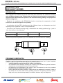
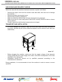
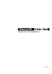
1
HE2020.com.au
Hospitality Equipment 2020 P/L
Unit 6/6 Tennyson Street, Clyde, NSW, 2142 Tel.02 9637 3737 Fax.02 9637 3434
DISHWASHERS
WITH PULL-THROUGH RACK
M115
INSTRUCTIONS
MANUAL
R03-06/03/2008
HE2020.com.au
Unit 6/6 Tennyson Street, Clyde, NSW, 2142 Tel.02 9637 3737 Fax.02 9637 3434 [email protected]
DECLARATION OF CONFORMITY
The following
hereby declares under full responsability that the following product
RACK CONVEYOR DISHWASHER
mod. M115
for which this declaration refers to the conformity of the following standards:
•
•
•
•
•
•
•
•
•
•
•
•
•
•
•
•
•
Safety of household and electrical appliances - General requirements EN60335-1(2002) + A1/A11(2004), A12 (2006) + A2 (2006)
Safety of household and electrical appliances - Part 2^
EN60335-2-58 (2005)
Particular requirements for commercial electric dishwashing machines
Household and similar electrical appliances – Electromagnetic fields – Methods for evaluation and measurements EN50366(2003)
+A1(2006)
Limits and methods of measurement of radio disturbance characteristics of electrical motor-operated and thermal appliances for
households and similar purposes, electric tools and similar electric apparatus - EN 55014-1(2000) + A1(2001) + A2(2002)
Limits for harmonic current emissions (equipment input current ≤ 16 A per phase) - EN 61000-3-2(2000) + A2 (2005)
Limitation of voltage fluctuations and flicker in low-voltage supply systems for equipment with rated current ≤ 16 A. EN 61000-3-3(1995)
+A1(2001) + A2(2005)
Immunity requirements for household appliances, tools and similar apparatus. Product family standard EN 55014-2(1997) + A1(2001)
Safety of machinery Basic concepts, general principles for design - Basic terminology, methodology-ISO 12100-1 (2003).
Safety of machinery - Basic concepts, general principles for design - Technical principles-ISO 12100-2 (2003).
on the basis of what is foreseen by the Directives:
2006/95/CE, 2004/108/CE, 2006/42/CE.
2006/95/EC, 2004/108/EC, 2006/42/EC.
We decline any responsability for injuries or damage derived from machine misuse, abuse by others or improper machine maintenance or repairs.
li 01/01/08
(date)
The administrator
HE2020.com.au
Unit 6/6 Tennyson Street, Clyde, NSW, 2142 Tel.02 9637 3737 Fax.02 9637 3434 [email protected]
WASTE OF ELECTRICAL AND ELECTRONIC EQUIPMENT DIRECTIVE (WEEE,RAEE in Italy)
AND SUBSEQUENT 2003/108/EC
2002/96/EC
The marking shown below indicates that the product cannot be disposed of as part of normal household waste.
Electrical and Electronic Equipment (EEE) can contain materials harmful to health and the environment, and
therefore is subject to separate waste collection: it must be disposed of at appropriate waste collection points or
returned to the distributor against purchase of new equipment of similar type or having the same functions.
The directive mentioned above, to which make reference for further details, provides for punitive actions in case of
illegal disposal of such waste.
LAMBER, manufacturer of this equipment, is enrolled in the Italian WEEE Register – the Register of Producers of
Electrical and Electronic Equipment- from the 18th /02/2008 with the number IT08020000000617.
HE2020.com.au
Unit 6/6 Tennyson Street, Clyde, NSW, 2142 Tel.02 9637 3737 Fax.02 9637 3434 [email protected]
MODEL
MODEL
M115
left-right
M115
right-left
WASHING
RINSING
5
HE2020.com.au
Unit 6/6 Tennyson Street, Clyde, NSW, 2142 Tel.02 9637 3737 Fax.02 9637 3434 [email protected]
TECHNICAL DATA AND DESCRIPTION
The table reported at page 5 shows the basic models of conveyor dishwashers and
identifies the single washing areas to which additional modules can be added to improve
their performance.
ACCESSORIES
COLD PRE-WASHING
STEAM CONDENSER - CVM
DRYING – ASM - MVM
ADDITIONAL RINSING - RIS
AUTOTIMER
SPLASH SHIELD (PMC-PMA-PMA/R)
BOOSTER PUMP
fan
fan
kW
kW
Motor
kW
Heat element
kW
TECHNICAL SPECIFICATIONS
Model:
version
Left-Right
1st speed
baskets/hour
Right-Left
2nd speed
ELECTRIC POWER
baskets/hour
kW
ELECTRICAL INPUT
A
ELECTRIC CABLE
mm2
CIRCUIT BREAKER
A
lcc ELECTRIC INPUT
6 kA
VOLTAGE
PRE-WASHING
TANK ELEMENTS
kW
ELECTRIC PUMP
kW
FIRST WASHING
TANK ELEMENTS
kW
ELECTRIC PUMP
kW
SECOND WASHING
TANK ELEMENTS
kW
ELECTRIC PUMP
kW
THIRD WASHING
TANK ELEMENTS
kW
ELECTRIC PUMP
kW
PRE-RINSING
TANK ELEMENTS
kW
ELECTRIC PUMP
kW
RINSING
BOILER ELEMENT
kW
BOILER ELEMENT
kW
GEARED MOTOR
kW
6
HE2020.com.au
Unit 6/6 Tennyson Street, Clyde, NSW, 2142 Tel.02 9637 3737 Fax.02 9637 3434 [email protected]
DESCRIPTION
CHARACTERISTICS
* Body and tank in stainless steel construction 18/10 AISI 304,
* Tunnel composition:
- 1 Wash
- wash arms : 3 upper + 2 lower
- 1 Rinse
- rinse arms : 1 upper + 1 lower
* Completely automatic,
* Upper and lower fixed washing ( 60 °C )
* Upper and lower fixed rinsing ( 85-90 °C )
* Washing and rinsing arms in stainless steel constructions, easy
and interchangeable,
* Double skin with thermic and acoustic insulation ;
* Slanted tank with rounded edges,
* Stainless steel autodraining washing pump,
* Counterbalanced door
* Front panel composition ::
- Main ON/OFF switch;
- Start pushbutton
- Stop pushbutton
- Emergency pushbutton
- Machine ON indicator
- Machine ready indicator
- Overload cutout indicator
* Frontal maintenance
* Automatic tank loading
* Rinse economizer
* Tank and pump filters
* Insulated Boiler
SAFETY
* Feet adjustable and strong
* Pressure-switch protection for Heating elements
* Thermic protection for washing pump
* Automatic stopping of pull-through in case of foreign bodies
* Low voltage control circuit (24V) for greater safety
during work operation
* Dishes (Stop with End Micro-switch on the exit table)
* Door opening safety device
7
disassembly
HE2020.com.au
Unit 6/6 Tennyson Street, Clyde, NSW, 2142 Tel.02 9637 3737 Fax.02 9637 3434 [email protected]
Contents
General norms
page
09
Introduction and safety norms
page
10
Unpacking and delivery checks
page
12
1 – INSTRUCTIONS FOR THE USER
page
13
First section - For the user – Operation before washing
page
14
Switch-on and use of the dishwashing machine mod. M115
Switch-on and use of the dishwashing machine mod. M115-ASM
page
page
16
18
Washing of dishes – During washing operations
page
21
After washing operations
page
23
Helpful suggestions - Achievements
page
24
Safety devices
page
25
Washing flow control system
page
27
Useful hints of stainless steel maintenance
page
28
2 – INSTRUCTIONS FOR THE INSTALLER
page
29
Installation
page
30
Second section - For the installer - Disposal
page
31
Positioning – Electrical connection
page
33
Water connections
page
34
Water draining - Steam feeding –
page
35
Steam exhaust – Vapours suction – Testing - Working temperatures
page
36
Torque limiter
page
37
Steam condenser - Autotimer
page
38
Modification of parameter’s programming
page
39
Possible drawbacks – causes - remedies
page
43
Table connection scheme
page
49
Wiring diagram
page
50
8
HE2020.com.au
Unit 6/6 Tennyson Street, Clyde, NSW, 2142 Tel.02 9637 3737 Fax.02 9637 3434 [email protected]
INSTRUCTIONS MANUAL DISHWASHING MACHINE
M115
The automatic-rack conveyor dishwashing machines of the M115 series are designed to
wash any kinds of dishes .
The modular system and the various optionals available allow the make-up of
dishwashing machines with the most appropriate features in order to meet your
production,space saving and energy-saving requirements.
GENERAL NORMS
ENGLISH
Tank You for purchasing our Dishwashing Machine.
Perfect washing-up results as far as hygiene concerns and a correct operation of the
dishwashing machine can be assured only in case the instructions reported in the
present manual are carefully followed.
We hope the information reported in the present manual will be helpful to You.
They are based on data and our best updated knowledge.
Carefully read the Instructions reported in the manual, recommendations and suggestions
included. Carefully read the terms of sale too, the ones limiting warranty included.
9
HE2020.com.au
Unit 6/6 Tennyson Street, Clyde, NSW, 2142 Tel.02 9637 3737 Fax.02 9637 3434 [email protected]
INTRODUCTION
AND SAFETY NORMS
INTRODUCTION
This equipment is destined only to the use it has been conceived for: tableware washing
such as dishes, glasses, cups, cutlery, trays, etc. Using it to wash machine components or
objects whose dimensions are superior to the machine working passage is improper and
therefore dangerous.
- Equipment in compliance with EEC89/336 directive concerning the suppression of radio
interferences and electromagnetic incompatibility.
- In conformity with the EEC directives and the fulfilment laws, our dishwashers are built
according to the regulations in force in Italy and abroad.
- The noise of the machine running empty, measured at the working positions (fig. 1) and at
1.6m from the floor, is the following:
Leq A Level equivalent
of sound pressure dB(A)
position 1
position 2
position 3
70
68
70
The level of peak sound pressure Lpc is not declared as it is much inferior to 130dB(C):
PRELIMINARY OBSERVATION
Carefully read the instructions reported in the present user manual, as it gives important
indications about safety of installation, operation and maintenance:
carefully keep the present manual for further consultations;
the illustrations and drawings showing the machine are intended for general reference
only and are not necessarily accurate in every particular;
-
the dimensions and characteristics of the machine, given in this Manual, are not to be considered
binding and may be changed without prior notice;
-
having removed the packing material, check that all the equipment is present. If there is
any doubt, do not use it and contact qualified personnel. The packing elements (plastic
bags, nails, etc.) should be kept away from children, because they are dangerous.
10
HE2020.com.au
Unit 6/6 Tennyson Street, Clyde, NSW, 2142 Tel.02 9637 3737 Fax.02 9637 3434 [email protected]
GENERAL SAFETY REGULATIONS
THIS SAFETY CODE HAS BEEN COMPILED IN YOUR INTEREST. Strict adherence to
these rules will reduce the risks of injury both to yourself and to others;
Personnel working with this machine must adhere strictly to all statutory safety regulations as
well as the specific rules listed below. Failure to do so may result in personal inyury and damage
to the machine;
DO NOT attempt to move, install, set-up or operate this machine until you have read and
fully understood this Manual. If doubt persists, ask your supervisor;
never leave tools, parts or other loose material on or in the machine;
Before switching the equipment the equipment on, make sure that the model plate data
conforms to that of the electrical and water distribution network;
remember that even with the mains isolator in the “OFF” position, the incoming cables are
still live;
BEFORE starting machine o cycle, after any maintenance or repair work, make sure all
protective are correctly installed;
be vigilant at all times, remember that your safety and that of your fellow workers depend
on you;
when moving or lifting the machine, care must be taken to comply with all the relevant
regulations governing such operations;
installation should be carried out by qualified personnel according to the manufacturer's
instructions.
this equipment should be destined to the use which it has been conceived for. Any other
application should be considered improper and consequently dangerous;
the equipment should only be used by personnel trained for its use;
SPECIAL SAFETY REGULATIONS
-
-
adjustement and repairs must be carried out only by personnel qualified. Repair carried
out by unskilled personnel may be dangerous;
perfect washing-up results as far as hygiene concerns and a correct operation of the
washing machine can be assured only in case the instructions reported in the present
handbook are carefully followed;
the machine must be only used by authorized personnel which must comply with sanitary
measures;
do not leave the machine in environment with temperatures inferior to 0°C;
the machine protection degree is IP55 for Control board and IP32 for machine, therefore
it should not be washed with direct high pressure jets of water;
11
HE2020.com.au
Unit 6/6 Tennyson Street, Clyde, NSW, 2142 Tel.02 9637 3737 Fax.02 9637 3434 [email protected]
UNPACKING AND DELIVERY CHECKS
When the case with the machine has been received, unpack it as follows:
-
Remove the upper cover and the wooden case side walls, take care not to damage
the machine,
Remove possible accessories boxes,
Remove the protecting cellophane,
Make sure that the machine has not been damaged during transport,
Make sure that all covers and panels have been correctly fixed and that no loosen
part is present,
Visually inspect that all electrical components are integral.
TRANSPORT AND INSTALLATION
-
To lift and transport the machine, insert the truck forks under the frame connected to
the points indicated by the yellow adhesives applied on the machine front side (see
draw below).
disforchem115
draw “A”*
-
-
Before plugging the machine, make sure that the supply voltage of the domestic
wiring system and the water supply from water connection corresponds to the ones
reported on the rating plate
Installation should be carried out by qualified personnel according to the
manufacturer's indications
During instalation, it is recommended to level the machine in order to ensure a correct
operation.
12
HE2020.com.au
Unit 6/6 Tennyson Street, Clyde, NSW, 2142 Tel.02 9637 3737 Fax.02 9637 3434 [email protected]
INSTRUCTIONS FOR THE
INSTALLER
The following instructions are addressed to a qualified personnel, the only one
authorised to carry-out checks and repair, if any.
The Manufacturer declines any responsibility in the case of interventions
made by a non qualified personnel.
HE2020.com.au
Unit 6/6 Tennyson Street, Clyde, NSW, 2142 Tel.02 9637 3737 Fax.02 9637 3434 [email protected]
M115
Second Section - FOR THE INSTALLER
The following instructions are addressed to qualified personnel who is the only one
authorized to carry out the inspections and the necessary repairs.
The machine should be installed in “Normal” environment, that is to say, indoors, free of
dust, explosion-proof and adequately lit and well aired.
Before installing the machine, it is necessary to arrange the electric and water
connections.
See the reported wiring diagram (supplied by the manufacturer) of the selected model as
far as the dimensions of pipes, cables and wall-mounted switch are concerned.
In order to prevent damages caused by the escape of vapours from the equipment, make
sure that adjacent materials do not deteriorate in their presence.
The Manufacturer cannot assume any responsibility for any damage to persons or
property deriving from the non-observance of the above specified norms.
DETERGENTS
The machine should also be equipped with a detergent and brightener dispenser, which
shall be supplied by the manufacturer of these products.
N.B.: If you use chlorinated sanitizers, it is always advisable to employ an automatic
dispenser provided with feeler for the measurement of the detergent concentration,
because brownish spots can form on the surfaces due to chlorine reactions when pouring
the detergent directly into the tank. The feeler for the measurement of concentration must
be placed on the front side of the tank through the hole “A” preset for such operation
(see drawing on page 28).
In any case the LIQUID DETERGENT shall be introduced through the preset hole “B” on
the front side of the washing tank.
Choice of the suitable cleansing agent is an essential condition if you want to obtain
extremely good washing results as concerns hygienic results.
It is then important to consider some points.
First of all only highly alkaline and chlorine-active antifoam products, especially made for
industrial dish-washing machines, must be used and they must be produced by well
known reliable Firms. We provide a short list just as an indication: Ecolab-Soilax; Henkel;
Lever; Diversey; Relativ.
The average concentration of liquid detergents must be 2÷4g/lter. In any case it is
essential that the producer of the detergent rules the dosage properly according to the
features of the installation.
HE2020.com.au
Unit 6/6 Tennyson Street, Clyde, NSW, 2142 Tel.02 9637 3737 Fax.02 9637 3434 [email protected]
As regards the introduction of the liquid rinse aid product, use the passage “C” ,
placed near the water inlet group.
This coupling will allow an appropriate introduction of the liquid rinse aid product.
In order to do this use a fitting with non-return valve.
0201455
0200196
For the electrical connection of these dosing pumps join the auxiliary contacts of the
contactors MT5 (detergent pump) and MT4 (rinse aid pump) into the lower electric box
(standard M115 model) or the blue terminals into the upper electric box (M115 with
drying tunnel), marked by special tags.
Note: In order to let cables pass, please use the labelled wire clamp behind the electrical
control box.
DISPOSAL
At the end of its life, the machine shall be disposed according to the local laws in force by
specialized and acknowledged companies in this field. Its components shall be
distinguished as follows:
-
metallic components: body, plans, frames, filters;
electric components: motors, remote control switch, microswitches, wiring;
plastic components: baskets, connections;
rubber components: hoses, sleeves.
32
HE2020.com.au
Unit 6/6 Tennyson Street, Clyde, NSW, 2142 Tel.02 9637 3737 Fax.02 9637 3434 [email protected]
electric cable must be of the following
type H07RN-F.
POSITIONING
During installation, carry out a good levelling
of the machine in order to make it correctly
work (doors, basket forward feeding).
In order to do so use the adjustable feet.
For a correct selection of the cable rated
cross-section refer to the data reported
on the product data plate.
The cable cross-section shall not be
inferior to the one indicated in the
“Technical data and description” reported
in the first page of the present manual.
The cable shall be connected to the
terminal L1-L2-L3 and to the adjacent
yellow-green terminal,on the electric box,
it shall be made passed and stopped by
means of the apposite cable grip.
After removing front panels, position the
machine over the connections. Assemble the
inlet and outlet shelves for basket loading
and unloading. The limit switch FC1 is
located on the outlet shelf or on the machine
delivery if the shelf is not provided for. The
limit switch shall be connected to the outlet
shelf.
The machine shall also be equipped with
detergent and brightener dispenser, which
shall be supplied by the manufacturer of these
products.
It is necessary to connect the equipment
to an effective ground installation, as
specified by the electrical safety
regulations in force.
Chack that this basic requirement is
complied with and, in case of doubt, ask
for a careful check of the installation by a
qualified personal.
In addition, the equipment shall be part of
an
equipotential
system,
the
effectiveness of which should be checked
according to the regulations in force.
The connection should be made at the
screw marked by the respective label
ELECTRICAL CONNECTION
Before connecting the machine,
check to make sure the voltage
outlet of the mains is the same as
the voltage specified on the data
plate of the machine.
It is also necessary to check that the
counter, the mains and the intake are
adequately dimensioned to withstand the
required maximum load.
located on the equipment lower side ( ).
It is recommended to make the electric
line be checked by your own designer.
A main switch must be installed between
the mains and the machine. This safety
measure also requires that the minimum
distance between the switch contacts is
at least 3 mm and the disconnection on
all poles according to EN 60204 (VDE
113).
THE
MACHINE
SHALL
BE
CONNECTED WITH AN EFFECTIVE
GROUND CLAMP.
The manufacturer declines any
responsibility for any damages
caused by lack of an effective
ground installation.
The mains must be wired to be able to
handle the current drawn by the
machine.The system must also be
provided with a proper ground lead in
accordance with the existings norms. The
33
HE2020.com.au
Unit 6/6 Tennyson Street, Clyde, NSW, 2142 Tel.02 9637 3737 Fax.02 9637 3434 [email protected]
N.B.: Each machine is equipped with a
pressure reducer near the water inlet
valves.
In order to obtain an optimum rinse it is
necessary to adjust it from 0,6 to 1 bar
according to inlet water pressure and
temperature.
(remember that the required dynamic
pressure must be 2÷4 bar (200÷400kPa)
and that inlet water temperature must be
55÷60°C for standard machines).
WATER CONNECTIONS
Carefully comply with any national or
regional regulations in force.
Hot water supply
Arrange a gate valve in an easily
accessible place, with a tap having a
3/4"gas thread spout at its end and
connect to the water inlet valve (fig.1)
If a variation of rinse pressure is required
while installing, proceed as follows:
1: make the machine work and check that
the rinse is activated;
2: Take away the upper protection plug on
the reduction gear and turn the proper
adjusting screw anti-clockwise in order to
decrease pressure or clockwise in order to
increase it or to restore the optimum
working conditions (see picture 1A).
-
temperatur between 55° and 60°C,
Dynamic Pressure 2÷4 bar (200÷400
kPa),
Hardness between 7,2 and 12,5 °F
N.B.: Each machine is equipped with a
pressure reducer. In order to obtain an
excellent rinsing, it shall be calibrated
according to the data reported on the plate
located in connection with the reducer
itself.
PIC.1A- PRESSURE REDUCER
Cold water supply
This connection is required only for
machine with steam condenser .
Water shall be supplied at a temperature
ranging from 10÷15°C and at a dynamic
pressure of 2÷4 bar (200÷400 kPa).
34
HE2020.com.au
Unit 6/6 Tennyson Street, Clyde, NSW, 2142 Tel.02 9637 3737 Fax.02 9637 3434 [email protected]
WATER DRAINING
Reachable from the machine front side
after opening the front panel (to do this
turn the two front screws out);
Arrange a discharge at floor level provided
with siphon and connect to the floor drain by
means of a hose provided with an adequate
inclination. Make sure the drain hose is not
choked in any way.
Make sure the drain hose is resistant to a
temperature of 70 °C.
Carefully comply with any national or regional
regulations in force.
STEAM FEEDING *
As far as steam feeding is concerned,
connect to the machine fittings indicated
in the installation drawings. In order to
make the equipment independent from
the general steam distribution network, it
is necessary to use gate and gas on/off
valves (see draw 2 and 3)..
This type of feeding should be supplied at
a pressure ranging from 1 bar (100°C) to
2 bar (121°C).
STEAM EXHAUST *
The condensed steam exhaust shall have
an appropriate slope toward the recovery
installation or a blow-by pump, in order to
guarantee an autonomous scavenging of
the condensed steam.
The steam used should be absolutely
saturated and dry.
N.B.: for possible maintenance operations,
it is advisable to arrange a gate valve
parallel with the discharge so that it is
possible to deviate condensation towards a
runoff pit.
* for steam machines only
35
HE2020.com.au
Unit 6/6 Tennyson Street, Clyde, NSW, 2142 Tel.02 9637 3737 Fax.02 9637 3434 [email protected]
VAPOURS SUCTION
WORKING TEMPERATURES
For machines equipped with splashguard
with collar or normal collar, carry out the
necessary connection as showed in fig. 4.
Check that the thermostats are set
according to the following working
temperatures.
WASHING
The tank thermostat (CT3), also placed
near the wash tank, will be set according
to the following temperature:
Washing water: 55÷60°C.
RINSING
The rinsing thermostat (CT2) will be set
according to the following temperature:
Rinsing water: 80÷85°C.
DO
NOT
TAMPER
WITH
THERMOSTAT CALIBRATION
In any case it is necessary to provide a
way to scavenge steam through a hood
or a similar system.
TESTING
Before starting machine:
During the testing operations, prior to
switching the dishwashing machine on,
check that thermostat of the rinsing boiler
(0°-90° C) is set to zero and the direction
of rotation of the pumps is correct.
Should the pumps rotate in the reverse
direction, reverse two wires of the line .
Make a number of empty racks to pass
through, then check that water jets are
sprinkled fron the rinsing nozzles then
adjust the thermostat of the boiler to 85° C
.
36
THE
HE2020.com.au
Unit 6/6 Tennyson Street, Clyde, NSW, 2142 Tel.02 9637 3737 Fax.02 9637 3434 [email protected]
TORQUE LIMITER
The limiter has already been described at
paragraph “SAFETY DEVICES”.
It is located in connection with the drawbar
and it is calibrated during testing by the
manufacturer.
In case it is necessary to calibrate it again,
proceed as follows:
1. Switch the machine off ;
2. Remove the protection panel;
3. Load the whole drawbar with baskets
full of dishes to be washed;
4. Loose the axial ring nut with the
hexagon ring wrench type “A”;
5. Disengage the friction with a hooked
key type “B” so that it slips;
6. At this point clockwise turn until the
drawbar manages to carry the whole
dishes charge;
7. The device is considered adequately
calibrated when the drawbar hardly
manages to carry the whole charge in
second gear.
37
HE2020.com.au
Unit 6/6 Tennyson Street, Clyde, NSW, 2142 Tel.02 9637 3737 Fax.02 9637 3434 [email protected]
This valve rules the water flow in the vapour
condensing battery.
STEAM CONDENSER
As regards the machines provided with
“vapour condensing” device, pay attention to
the following:
If the machine needed a more precise
adjustment, under regular conditions, adjust
the valve until no more vapour comes out of
the “vapour condensing” cap.
The adjustment of the device is carried out by
means of the regulator valve (COCK “V”)
placed inside the machine base plate and
marked with its special label.
Generally it is sufficient to slightly open the
valve.
ATTENTION! An excessive opening can
cause the cooling of the tank.
The Manufacturer should rule this cock while
testing the machine.
Never touch this cock without a specific
reason.
WASHING AUTOTIMER
Thanks to the AUTOTIMER device it is
possible to reduce water and power
consumption when the machine is not used.
As default the function ‘Autotimer’ is disabled.
It’s possible to program the times of stop of
4’-6’-8’ (calculated from when the last rack
has come out) by setting up the dip-switch
positioned on the electronic card that is in the
control box.
Look at the following diagrams:
ON
1 2 3 4
AUTOTIMER
OFF
1 2 3 4
4’ min
1 2 3 4
6’ min
1 2 3 4
8’ min
OFF
Disabled Autotimer :
ON
OFF
Autotimer after 4’ min. :
ON
OFF
Autotimer after 6’ min. :
ON
OFF
Autotimer after 8’ min. :
38
HE2020.com.au
Unit 6/6 Tennyson Street, Clyde, NSW, 2142 Tel.02 9637 3737 Fax.02 9637 3434 [email protected]
MODIFICATION OF PARAMETERS’ PROGRAMMING
L
M N
P
O
A
R
Q
B
C1
C2
7
1
1
2
3
4
5
6
7
F
V
H
G
E
D
1.
Make sure that the wall switch is on;
2.
Give power to the machine by the main selector which is placed on the top of the control box: the
thermometer display “C1-C2” will turn on, as well as the information display “V”, where “OFF” will
appear;
3.
Push on the “H-G-D” buttons at the same time : on the display “PARAMETERS” will appear ;
4.
Push “G”(start) in order to see all the parameters in sequence (see complete list on the following
page); (with the “H”(stop) button it is possible to go back to the previous parameter )
5.
Modify the parameter acting on the “E” button to reduce and on the “D” button to increase the value of
this parameter;
6.
To validate the value of the modified parameters it is necessary to push the button “G”(start) until the
last “OFF” appears;
7.
Push the “A” line button (on the information display you’ll see that “ON” will appear);
8.
Start the machine and check the right value of the established parameters.
39
HE2020.com.au
Unit 6/6 Tennyson Street, Clyde, NSW, 2142 Tel.02 9637 3737 Fax.02 9637 3434 [email protected]
PARAMÈTRES MATIC
Description
Default (Reset)
Langue
Italiano
Pre-rinçage (Oui-Non)
Non
Start pre-rinçage 1 (0-240s)
2s
Start pre-rinçage 2 (0-240s)
1s
Duréé pre-rinçage 1 (0-240s)
2s
Duréé pre-rinçage 2 (0-240s)
1s
Séchage (Oui-Non)
Non
Pompe à chaleur (Oui-Non)
Non
Debitmètre Rinçage (Oui-Non)
Non
Vitesse (1-2)
2
Auto timer(0-20min)
0min
Chargement surchauffeur (0-10min)
2min
Stop chargement cuve (0-60s)
30s
Alarme chargement cuve (0-60min)
20min
Start rinçage 1 (0-240s)
0s
Start rinçage 2 (0-240s)
0s
Stop rinçage 1 (0-240s)
1s
Stop rinçage 2 (0-240s)
1s
Temps vidange Cuve (0-15min)
0min
Start après Fin de Course (0-10s)
3s
Niveau (0-240s)
10s
Arrêt Lavage (0-250s)
0s
Paramètre d’entretien
Service (0-2500)
500
Blocage machine (Oui-Non)
Non
Paramètres
Modifiés
RÉTABLISSEMENT DES PARAMÈTRES D'USINE:
1- Presser au même temps les touches "H (stop)-G (start)- A (I-O)"
2- En gardant préssées les touches mentionnées ci-dessus, donner tension à la machine en agissant sur le
sectionneur général placé sur le panneau de contrôle.
36
HE2020.com.au
Unit 6/6 Tennyson Street, Clyde, NSW, 2142 Tel.02 9637 3737 Fax.02 9637 3434 [email protected]
MATIC PARAMETERS’ DESCRIPTION
Description
Parameter functioning
Language
Select the language to use: Italian-French-English-GermanSpanish.
Select YES only for machines with pre-rinsing. This function can be
activated or not by pressing ‘’P’’ button.
a: (for machines with Pull-through rack) lag at the pre-rinsing pump
start from the moment of the basket contact with the rinsing
economizer at the first speed .
b: ( for Belt-towing machines) lag at the pre-rinsing pump start
from the moment of the basket or dish passage between the entry’s
photoelectric cells at the first speed.
a: (for machines with Pull-through rack) lag at the pre-rinsing pump
start from the moment of the basket contact with the rinsing
economizer at the second speed .
b: ( for Belt-towing machines) lag at the pre-rinsing pump start
from the moment of the basket or dish passage between the entry’s
photoelectric cells at the second speed.
a: (for machines with Pull-through rack) lag at the pre-rinsing pump
stop from the moment of the exit of the basket contact with the
rinsing economizer at the first speed.
b: (for Belt-towing machines) lag at the pre-rinsing pump stop from
the moment of the dish or basket exit from the entry’s photoelectric
cells at the first speed.
a: (for machines with Pull-through rack) lag at the pre-rinsing pump
stop from the moment of the basket contact with the pre-rinsing
economizer at the second speed.
b: (for Belt-towing machines) lag at the pre-rinsing pump stop from
the moment of the dish or basket exit from the entry’s photoelectric
cells at the second speed.
Select YES only for machines with drying tunnel. This function can
be activated or excluded by ‘’O’’ button.
Select YES only for machines with heat pump. This function can be
activated or excluded by ‘’Q’’ button.
Select YES only for machines with flow-meter. It checks the rinsing
water quantity. Lamp ‘’M’’ is lighted up when the rinsing functioning
is regular; when the water quantity is inadequate lamp ‘’M’’ flashes
and the display shows ‘’RINSING ALERT’’.
Select -1- for machines with only one speed and select -2- for
machines with two speeds. ‘’E’’ button allows to select the
conveyor’s or belt-towing ’s speed. The corresponding lamp ‘’F’’ will
be lighted up.
Only for machines with autotimer. Select a time from 1 to 20
minutes to activate it. This function anyway can be activated or
excluded by ‘’R’’ button.
It stops the machine after the selected time from when the last
basket or dish has passed by the rinsing economizer.
At every daily start, before filling the tanks, the rinsing system is
activated to guarantee the water presence in the boiler. Regulate
the time according to the single needs or boiler dimensions.
Time during which the tank filling has to continue after having
reached the level of the level switch to reach immediately the
optimal functioning level.
Pre-rinsing (Yes-No)
Pre-rinsing Start 1 (0-240s)
Pre-rinsing Start 2 (0-240s)
Pre-rinsing duration 1 (0-240s)
Pre- rinsing duration 2 (0-240s)
Drying (Yes-No)
Heat pump (Yes-No)
Flow-meter (Yes-No)
Speed (1-2)
Autotimer (0-20min)
Boiler filling (0-10min)
Tank filling stop (0-60s)
37
HE2020.com.au
Unit 6/6 Tennyson Street, Clyde, NSW, 2142 Tel.02 9637 3737 Fax.02 9637 3434 [email protected]
Tank filling alert (0-60min)
Rinsing Start 1 (0-240s)
Rinsing Start 2 (0-240s)
Rinsing duration 1 (0-240s)
Rinsing duration 2 (0-240s)
Tank drain time (0-15min)
Start after the conveyor limit stop (010s)
Level (0-240s)
Washing stop (0-250s)
CALL SERVICE (500-2500)
STOP MACHINE (YES-NOT)
Maximum time for the tank filling, after which the machine stops
and the display shows this trouble. Alert in case of lack of water or
anomaly on the machine drain system.
a: (for machines with Pull-through rack) lag at the rinsing start
from the moment of the basket contact with the rinsing economizer
(at the first speed) .
b:
( for Belt-towing machines) lag at the rinsing start from the
moment of the basket or dish passage between the entry’s
photoelectric cells (at the first speed).
a: (for machines with Pull-through rack) lag at the rinsing start
from the moment of the basket contact with the rinsing economizer
(at the second speed) .
b:
( for Belt-towing machines) lag at the rinsing start from the
moment of the basket or dish passage between the entry’s
photoelectric cells (at the second speed).
a: (for machines with Pull-through rack) lag at the rinsing stop from
the moment of the exit of the basket contact with the rinsing
economizer (at the first speed).
b: (for Belt-towing machines) lag at the rinsing stop from the
moment of the dish or basket exit from the entry’s photoelectric
cells (at the first speed).
a: (for machines with Pull-through rack) lag at the rinsing stop from
the moment of the basket contact with the rinsing economizer (at
the second speed).
b: (for Belt-towing machines) lag at the rinsing stop from the
moment of the dish or basket exit from the entry’s photoelectric
cells (at the second speed).
Only for machines with automatic drain valve. It fixes the time of
the drain cycle.
Lag time for the restart of the conveyor or of the belt-towing after
the stop by the conveyor limit stop to allow to clear the exit table.
This lag is activated also at the start of the washing or of the
conveyor.
Waiting time for the tank level reset at the washing pumps’ start.
It can be useful if the machine is equipped with Autotimer and
subject to frequent stops and restarts.
Washing stop at limit stop.
It allows to stop the washing after some time, from the moment of
the baskets stop at the limit stop.
The parameter can be set from 0 to 250 seconds.
It allows to fix after how many hours of utilization the dishwasher’s
maintenance has to be done. The parameter can be regulated from
0 to 2500 hours.
This parameter allows to stop the machine after 50 hours of working
since the flashing word ‘’CALL SERVICE’’ appeared on the display.
38
HE2020.com.au
Unit 6/6 Tennyson Street, Clyde, NSW, 2142 Tel.02 9637 3737 Fax.02 9637 3434 [email protected]
A LIST OF DRAWBACKS POSSIBLY OCCURRING WITH THE USE OF THE
DISHWASHING MACHINE, THEIR CAUSES AND POSSIBLE REMEDIES
1 - Lamp D (LS1) does not turn on upon switching the machine on
A - Check that the wall-mounting swith is ON and the respective fuses are not burnt.
B - Maybe lamp LS1 has burnt. In this case, replace it. The machine can work anyway .
2 - Lamp M (LS3) of overload cutout devices, ON
A - Chek that the overload cutouts of the individual remote switches and replace those
disconnected . If such a drawback occurs several times in the same device, it is suggested to
increase the current rate through the graduated cursor.
B - Check that the power supply voltage is not subjected to variations in ecces of 10% of the
nominal value .
C - Check, by using an ammeter, that the current drained by the motor does not exceed the
rated values .
3 - The tank don't fill, lamp G (LS2) does not turn on
A - Check that pressures switches CP1-CP2 (those existing) are effective and calibrated.
B - Check that the feeding water intercept is open and water is present in the piping system .
C - Check that the overflows are in their housing.
D - Check that the solenoid valve EV2 is effective and gets tension.
4 - The racks don't step up, feeding rod still
A - Check that nothing is resting on limit switch micro FC1 and this is in good operating
conditions .
B - Check that there are no objects got stuck inside the tunnel between the feeding group
and the fixed part of the machine.
C - Check that the locking ringnut of the friction clutch in speed reducer M01-M01A1 is not
slackened, if otherwise tighten it slowly until the feeding system operates.
D - Check that the overload cutout RM01 is not triggered, otherwise restore it. This
drawback is displayed by lamp M (LS3) being ON .
E - Check that the remote switch coil MT04 is effective.
F - Check that speed reducer M01 is in good operating conditions .
5 - The racks don't step up, feeding rod moving
A - Check whether one or several pawles are blocked .
B - Check that the central rack of the rack is effective .
6 - The racks don't stop at end of stroke
43
HE2020.com.au
Unit 6/6 Tennyson Street, Clyde, NSW, 2142 Tel.02 9637 3737 Fax.02 9637 3434 [email protected]
A - Check that the wheel of micro FC1 projects sufficiently from the bracket and is operated
by the shelf.
B - Check that micro FC1 is effective and the respective cable is connected correctly.
7 - The tanks don't stop being filled upon reaching the desired level
A - Check that the trap of the pressure switch has no porosities and the connection pipe is
not disconnected .
B - Check that the pressure switch is in good conditions and is calibrated .
C - Check that there is no dirty in the solenoid valve. This drawback can be noted because
the machine continues to load water, whilst the main on/off switch is off .
8 - Insufficient washing
A - Check that the detergent is effective, of the type for industrial dishwashing machines, and is
proportioned for the right concentration .
B - Check that the detergent container is not empty and operates correctely .
C - Check that the jets of the washing and pre-rinsing arms are not clogged. If necessary, clean
them.
D - Check that the dishes are placed in the respective racks. Soup plates have to be mandatorily
placed in rack type P12-16.
E - Check that the temperatures in the tanks are the specified ones.
F - One or several pumps don't operate, in this case check that:
- the overload cutuot didn't switch the pump in question and, if necessary,restore it (this
drawback is displayed by lamp M (LS3) being ON)
- the coil of the respective remote switch are not broken
- finally, the pump is not blocked, the motor is effective and rotates in the right direction.
PUMPS ELECTRICAL COMPONENTS
1st wash
PUMP
CONTACTOR
CUTOUT
M02
MT5
RM2
H - Shadings or spots present on dishes,specially on glasses, may be caused by minerals present in
the water. In such an event, it is suggested to analyze the water used. The contents of calcium and
magnesium in the water should not exceed 10°F. The presence of iron should not exceed 0,1 ppm. If
these values are exceed, it is suggested to treat the water as appropriate .
I - A preliminary softening is suggested prior to washing knives, forks and spoons
44
HE2020.com.au
Unit 6/6 Tennyson Street, Clyde, NSW, 2142 Tel.02 9637 3737 Fax.02 9637 3434 [email protected]
9 - Temperatures insufficient in one or several tanks
A - Check that the thermostats are effective and calibrated .
B - Check that the temperature of the feeding water is from 50° to 60° C, as specified .
C - Check that the thermostats relevant to the tanks are set to the right temperatures and
operate correctely .
D - Check that the fuses and the coil of the remote switch are not broken .
E - Check that the heater elements are effective .
HEATER ELECTRICAL COMPONENTS
TEMPERATURE
HEATERS
THERMOSTATS
CONTACTORS
1st wash
50°-60°C
R2
CT3
MT2
10 - Rinsing insufficient
An effective rinsing also depends on correct washing operations . Therefore, prior to
checking the rinsing system, make sure that washing took place correctly, and specifically
look at item X in the respective paragraph. Having ascertained that washing was made
correctly, check that :
A - The dynamic pressure of the feeding water is not less than 2 bars. Should the pressure
be insufficient, install rinse buster pump M07 in order to increase pressure .
B - The nozzles are not clogged by calcareous residuals and they are oriented to the right
direction .
C - Water inlet solenoid valve EV1 operates correctly.
D - The water input filter is not clogged
E - Energy-saver microswitch FCE1 and FCP9 are effecteive .
F - The curtain of the last tank is in the right position and does not cover the rinsing nozzles
when dishes pass there .
G - The boiler is not scaled to such an extent as to limit the water flow rate.
11 - Insufficient Rinsing temperature
The temperature of the rinsing water should range from 80° to 90° C.
Should it be lower.check that :
A - The thermometer is effective and calibrated .
B - The temperature of the feeding water ranges from 50° to 60° C specified (excluding
machines with drain heat recovery unit) .
C - The dynamic pressure of the feeding water does not exceed 2 bars. If so, calibrate the
pressure reducer incorporated in the machine.
D - The rinsing nozzles have not been unduly widened or replaced.
E - The thermostats relevant to boiler CT2 is set to the right temperature and operate
correctly.
45
HE2020.com.au
Unit 6/6 Tennyson Street, Clyde, NSW, 2142 Tel.02 9637 3737 Fax.02 9637 3434 [email protected]
If the drawback is not due to any of the causes listed hereabove,proceed as follows :
for machines with electric heating
- check that the coil of remote switch MT03 is not broken
- check all elements of boiler heaters R1
- check the security thermostat CT1 is on
for machines with steam heating
- check that the steam inlet gate is open and it is present with a pressure not less than 0,5
bars,
- check that the filter of the condensated steam drainage is not clogged;
- check that steam solenoid valve EV7 operates correctly,
- check that the input steam filter is not clogged to such an extent as to prevent the normal
flow rate,
- check that the condensated steam outlet pipe can freely drain by drop,
- check that the pipe-coil of the boiler is not scaled to such an extent as to limit the heat
exchange thereof .
12 - Insufficient drying
An effective drying is strictly related to an effective washing and rinsing. Prior to checking the
drying system, check whether washing and rinsing have been made correctly. Then check
that :
A - The rinse agent liquid container is not empty and the respective proportioner operates
correctly.
B - The air suction holes located on the upper panel are not clogged by foreign bodies.
C – The Overload cutout is not triggered. If so, restore it. This drawback is displayed by
lamp M (LS3) being ON.
D - Fuses and remote switch coil MT09 are not broken.
E - Motor M05 is not blocked and rotates in the right direction.
F - Using a maximum thermometer, check that the temperature of the hot air jet is at least
80° C. Should it be lower, proceed as follows :
for machines with electrical heating
- check that thermostat CT6 is set to the right position and operates correctly.
- check that fuses and remote switch coil MT07 are affective.
- check that heater element R3 are effective.
for machines with steam heating
- check that the steam inlet gate is open and is present with a pressure not less than 0,5
bars,
- check that the filter of the condensated steam drainage is not clogged;
- check that steam solenoid valve EV7 operates correctly,
- check that the input steam filter is not clogged to such an extent as to prevent the normal
flow rate,
46
HE2020.com.au
Unit 6/6 Tennyson Street, Clyde, NSW, 2142 Tel.02 9637 3737 Fax.02 9637 3434 [email protected]
- check that the condensated steam outlet pipe can freely drain by drop.
12 - Insufficient aspiration and steam condensation
A - Check whether foreign bodies obstruct the upper air exhaust hole .
B - Check that the filter of the condenser battery is not clogged by fat residuals. In such an
event, wash it with boiling water and detersive. Rinse thoroughly.
C - Check that overload cutout is not triggered. If so, restore it. This drawback is dispalyed
by lamp M(LS3) being ON .
D - Check that fuses and remote switch coil MT16 are not broken.
E - Check that motor M08 is not blocked nor burnt and rotates in the right direction
F - Check that the cold water feed cock is open and water is present at a pressure of at
least 2 bars.
G - Check that cold water inlet filter D is not clogged to such an extent as to limit the flow
rate.
The manufacturer declines any responsibility for any misprints contained in this
booklet. The Manufacturer also reserves the right to make any modifications to its
products that don't affect the basic characteristics thereof.
47
HE2020.com.au
Unit 6/6 Tennyson Street, Clyde, NSW, 2142 Tel.02 9637 3737 Fax.02 9637 3434 [email protected]
ATTENTION !
ENGLISH
FOR A CORRECT WORKING OF THE
MACHINE (PUMPS, FANS, ETC.), PLEASE
CHECK THAT THE PULL-THROUGH
CRANK INSIDE THE MACHINE (FIG.”A”
) TURNS ANTICLOCKWISE, OR THAT THE
DRIVE MOTOR SHAFT UNDER THE
WASHING TANK (FIG.”B”) TURNS IN THE
DIRECTION INDICATED BY THE YELLOW
ARROW ON THE MOTOR BODY.
A
B
ETI-MANOV-TRAINO
48
HE2020.com.au
Unit 6/6 Tennyson Street, Clyde, NSW, 2142 Tel.02 9637 3737 Fax.02 9637 3434 [email protected]
TABLE CONNECTION SCHEME
MURO/MUR/WALL/WAND
Piano di lavoro, plan de travail
work table, Arbeitstisch
49
HE2020.com.au
Unit 6/6 Tennyson Street, Clyde, NSW, 2142 Tel.02
9637
Fax.02 9637 3434 [email protected]
Pagina
1 di 3737
6
ABBR.
AD1
BS1
BS2
BS3
BS4
CP1
CP2
CP3
CP4
CP5
CP6
CP7
CP8
CP9
CP10
CP11
CT01
CT02
CT03
CT04
CT05
CT06
CT07
CT08
CT09
CT10
CT11
CT12
CT13
CT14
CT15
CT16
CT17
CT18
EV01
EV02
EV03
EV04
EV05
EV06
EV07
EV08
EV09
EV10
EV11
EV12
EV13
EV14-15-16/A
EV17
EV18
COMPONENT
ANTI-JAMMING FILTER
BOILER SAFETY AUTOMATIC SWITCH RELEASE COIL
DRYING SAFETY AUTOMATIC SWITCH RELEASE COIL
SAFETY AUTOMATIC SWITCH RELEASE COIL FOR ADDITIONAL BOILER
SAFETY AUTOMATIC SWITCH RELEASE COIL FOR ADDITIONAL DRYING UNIT
LOWER PRESSURE SWITCH FOR MAIN WASHING
UPPER PRESSURE SWITCH FOR MAIN WASHING
PRE-WASH PRESSURE SWITCH
PRESSURE SWITCH FOR SECOND WASHING
PRE-RINSE PRESSURE SWITCH
PRESSURE SWITCH FOR SECOND PRE-WASHING
PRESSURE SWITCH FOR THIRD WASHING
PRESSURE SWITCH FOR RECYCLE PUMP
PRESSURE SWITCH FOR PRE-WASHING DRAIN
PRESSURE SWITCH FOR WASHING DRAIN
PRESSURE SWITCH FOR DRAIN PU MP M115
BOILER SAFETY THERMOSTAT
BOILER THERMOSTAT
THERMOSTAT FOR MAIN WASH TANK
MAXIMUM TEMPERATURE THERMOSTAT FOR PRE-WASH TANK
DRYING SAFETY THERMOSTAT
DRYING THERMOSTAT
THERMOSTAT FOR PRE-RINSE TANK
THERMOSTAT FOR SECOND WASH TANK
THERMOSTAT FOR PRE-WASH TANK HEATING
SAFETY THERMOSTAT FOR ADDITIONAL BOILER
THERMOSTAT FOR ADDITIONAL BOILER
THERMOSTAT FOR HEAT RECOVERER
THERMOSTAT FOR SECOND PRE-WASH HEATING
THERMOSTAT FOR THIRD WASHING
SAFETY THERMOSTAT FOR ADDITIONAL DRYING
THERMOSTAT FOR ADDITIONAL DRYING
DRYING STOP THERMOSTAT
ECONOMY THERMOSTAT
LOADING SOLENOID VALVE
RINSE SOLENOID VALVE
PREWASH COOLING SOLENOID VALVE
STEAM CONDENSER SOLENOID VALVE
HEAT RECOVERER ENTRY SOLENOID VALVE
HEAT RECOVERER EXIT SOLENOID VALVE
BOILER STEAM SOLENOID VALVE
STEAM SOLENOID VALVE - HEATED WATER IN THE MAIN WASH TANK
DRYING STEAM SOLENOID VALVE
STEAM SOLENOID VALVE - HEATED WATER IN THE SECOND WASH TANK
COLD PREWASH SOLENOID VALVE
STEAM SOLENOID VALVE - HEATED WATER IN THE MAIN PRE-WASH TANK
GAS-FIRED BOILER ENTRY SOLENOID VALVE (FROM RCL)/RECOVERER EXIT SOLENOID VALVE
SELF-WASHING AREAS SOLENOID VALVES
SELF-WASHING SYSTEM SOLENOID VALVE
TANK DRAIN SOLENOID VALVE
15/07/2009
HE2020.com.au
Unit 6/6 Tennyson Street, Clyde, NSW, 2142 Tel.02
9637
Fax.02 9637 3434 [email protected]
Pagina
2 di 3737
6
EV19
EV20
EV21
EV22
FC1
FC2
FC3
FC4
FC5
FCE1
FCE2
FCE3
FCE4
FCE5
FCE6
FCECL1
FCECL2
FCECL3
FCL1
FCL2
FCL3
FCL4
FCL4A
FCP01/01A
FCP02/02A
FCP03/03A
FCP04/04A
FCP05/05A
FCP06/06A
FCP07/07A
FCP08/08A
FCP09/09A
FCP10/10A
FCP11/11A
FCP12/12A
FCP13/13A
FCP14/14A
FCP15
FCSC1
FCSC2
FLS1
FS1-2-3
FS4
FS5
FS6
FS7
FS8
IA01
IA02
IA03
IA04
IA05
HEAT PUMP SOLENOID VALVE
PRE-WASHING LOADING SOLENOID VALVE
RINSE HEATING SOLENOID VALVE CVCP
TANK HEATING SOLENOID VALVE CVCP
LIMIT SWITCH FOR EXIT TABLE
LIMIT SWITCH FOR BASKET UNLOADING
SAFETY LIMIT SWITCH FOR BASKET UNLOAD CHAIN
SAFETY LIMIT SWITCH TOP 1 UNLOAD CHAIN
SAFETY LIMIT SWITCH
RINSING ECONOMIZER
PRE-RINSE ECONOMIZER
WASHING ECONOMIZER (SELF-TIMING)
MICROSWITCH FOR BUSY CORNER PREWASH AREA
MICROSWITCH FOR BUSY LOADING ENTER AREA
COLD PREWASH ECONOMIZER
MAIN WASH DRAIN OPENING CONTROL
PRE-WASH DRAIN OPENING CONTROL
SECOND WASH DRAIN OPENING CONTROL
PHOTOELECTRIC CELL FOR CORNER UNLOADING SYNCHRONISM
PHOTOELECTRIC CELL 1 CORNER UNLOADING
PHOTOELECTRIC CELL 2 CORNER UNLOADING
PHOTOELECTRIC CELL FOR LINEAR SELF-TIMER EMITTER
PHOTOELECTRIC CELL FOR LINEAR SELF-TIMER RECEIVER
MAIN WASHING DOOR LIMIT SWITCH
PRE-WASH DOOR LIMIT SWITCH
PRE-RINSE DOOR LIMIT SWITCH
SECOND WASHING DOOR LIMIT SWITCH
CORNER DRYING UNIT AND RCL DOOR LIMIT SWITCH
DOOR LIMIT SWITCH FOR ENTRY LINEAR BELT
DOOR LIMIT SWITCH FOR EXIT LINEAR BELT
SECOND PRE-WASH DOOR LIMIT SWITCH
DOOR LIMIT SWITCH FOR TANK LOADING M115
THIRD WASHING DOOR LIMIT SWITCH
DOOR LIMIT SWITCH FOR ADDITIONAL DRYING TUNNEL
DOOR LIMIT SWITCH FOR PREWASH-WASH NEUTRAL INTERMEDIATE
DOOR LIMIT SWITCH FOR WASH-RINSE NEUTRAL INTERMEDIATE
DOOR LIMIT SWITCH FOR LINEAR ENTRY TABLE FILTER
FOURTH WASHING DOOR LIMIT SWITCH
PREWASH DRAIN MICROSWITCH
MAIN WASHING DRAIN MICROSWITCH
RINSE FLOWMETER
MAIN SWITCH FUSES
PRIMARY TRANSFORMER FUSES FOR DETERGENT PUMP
PRIMARY TRANSFORMER FUSES FOR RINSE AID PUMP
FUSES FOR DETERGENT PUMP
FUSES FOR RINSE AID PUMP
PRIMARY TRANSFORMER FUSES FOR TEMPERATURE RECORDER
AUTOMATIC SWITCH PRIMARY TRANSFORMER
AUTOMATIC SWITCH SECONDARY TRANSFORMER
AUTOMATIC SWITCH FOR BOILER HEATING ELEMENT
AUTOMATIC SWITCH FOR MAIN TANK ELEMENT
AUTOMATIC SWITCH FOR PRIMARY TRANSFORMER FOR DOORS
15/07/2009
HE2020.com.au
Unit 6/6 Tennyson Street, Clyde, NSW, 2142 Tel.02
9637
Fax.02 9637 3434 [email protected]
Pagina
3 di 3737
6
IA06
IA07
IA08
IA09
IA10
IA11
IA12
IA13
IA14
IA15
IN0
IN1
IN2
IN3
IN4
IN5
IN6
LIV1
LIV2
LS1
LS2
LS3
LS4
LS5
LS6
LS7
LS8
LS9
LS10
M01
M01A
M02
M03
M04
M05
M06
M07
M08
M09
M10
M11
M11A
M12
M13
M14
M15
M16
M17
M18
M19
M20
MT01
AUTOMATIC SWITCH FOR SECONDARY TRANSFORMER FOR DOORS B191
AUTOMATIC SWITCH FOR DRYING HEATING ELEMENT
AUTOMATIC SWITCH FOR PRE-RINSE HEATING ELEMENT
AUTOMATIC SWITCH FOR SECOND TANK HEATING ELEMENT
AUTOMATIC SWITCH FOR PREWASH HEATING ELEMENT
AUTOMATIC SWITCH FOR ADDITIONAL BOILER HEATING ELEMENT
AUTOMATIC SWITCH FOR SECOND PREWASH HEATING ELEMENT
AUTOMATIC SWITCH FOR THIRD TANK HEATING ELEMENT
AUTOMATIC SWITCH FOR ADDITIONAL DRYING HEATING ELEMENT
AUTOMATIC SWITCH FOR DRAIN VALVES PROTECTION
MACHINE GENERAL ISOLATOR WITH FUSES
MACHINE START SWITCH 0-1-2
PRE-RINSE SWITCH
DRYING SWITCH 9KW
SELF-TIMER SWITCH
ADDITIONAL DRYING UNIT SWITCH
INVERTER SWITCH
DETERGENT LEVEL
RINSE AID LEVEL
TURN-ON LAMP
TANK LEVEL LAMP
OVERLOAD CUTOUT LAMP
LAMP FOR FREE CORNER PRE-WASH AREA
EMERGENCY LAMP FOR RINSING FLOWMETER
SELF-WASHING SYSTEM CYCLE LAMP
AUTOTIMER LAMP
START LAMP
DETERGENT LEVEL ALARM LAMP
DRAIN LAMP
TOWING GEARED MOTOR V1
TOWING GEARED MOTOR V2
MAIN WASH PUMP
PRE-WASH PUMP
FAN MOTOR
MOTOR FAN FOR DRYING UNIT
RINSE PUMP
BOOSTER PUMP
STEAM CONDENSER FAN MOTOR
SECOND WASH PUMP
HEAT RECOVERER FAN MOTOR
GEARED MOTOR FOR MOTORIZED CURVE V1
GEARED MOTOR FOR MOTORIZED CURVE V2
SECOND PRE-WASH PUMP
GEARED MOTOR FOR RACK UNLOAD TABLE
THIRD WASH PUMP
RECYCLE PUMP
ADDITIONAL MOTOR FAN FOR DRYING UNIT
MACHINE SELF-WASHING PUMP
DRAIN PUMP
HEAT PUMP COMPRESSOR
PUMP FOR DRAIN PUMP KIT M115
LEVEL CONTROL CONTACTOR
15/07/2009
HE2020.com.au
Unit 6/6 Tennyson Street, Clyde, NSW, 2142 Tel.02
9637
Fax.02 9637 3434 [email protected]
Pagina
4 di 3737
6
MT02
MT03
MT04
MT04A
MT04B
MT05
MT06
MT07
MT08
MT09
MT10
MT11
MT12
MT13
MT14
MT15
MT16
MT17
MT18
MT19
MT20
MT20A
MT21
MT22
MT23
MT24
MT25
MT26
MT27
MT28
MT29
MT30
MT31
MT32
MT33
MT34
MT35
MT36
MT37
MT38
MT39
MT40
MT41
MT42
MT43
MT44
MT45
MT46
MT47
MT48
PS01
PS02
HEATING ELEMENT CONTACTOR FOR MAIN WASH TANK
BOILER HEATING ELEMENT CONTACTOR
CONTACTOR FOR TOWING MOTOR
CONTACTOR FOR TOWING MOTOR (SECOND SPEED)
CONTACTOR FOR TOWING MOTOR (THIRD SPEED)
CONTACTOR FOR MAIN WASH PUMP
CONTACTOR FOR PRE-WASH PUMP
CONTACTOR FOR FAN MOTOR
CONTACTOR FOR HEATING ELEMENT OF DRYING UNIT
CONTACTOR FOR DRYING UNIT MOTOR FAN
CONTACTOR FOR PRE-RINSE PUMP
CONTACTOR FOR PRE-RINSE HEATING ELEMENT
CONTACTOR FOR DOOR MAGNETIC SWITCH (MATIC M39-49-59/LINEAR)
CONTACTOR-RELAY FOR RINSE ECONOMIZER (MATIC BOOSTER PUMP)
BOOSTER PUMP CONTACTOR
SECOND WASH PUMP CONTACTOR
CONTACTOR FOR STEAM CONDENSER FAN MOTOR
CONTACTOR FOR SECOND WASH TANK ELEMENT
CONTACTOR FOR HEAT RECOVERER FAN MOTOR
CONTACTOR FOR ADDITIONAL BOILER
CONTACTOR FOR MOTOR V1 MOTORIZED CURVE
CONTACTOR FOR MOTOR V2 MOTORIZED CURVE
CONTACTOR FOR PRE-WASH HEATING ELEMENT
CONTACTOR FOR LINEAR RINSE ECONOMIZER
CONTACTOR-RELAY FOR PHOTOELECTRIC CELL 1 BASKET UNLOADER
CONTACTOR-RELAY FOR PHOTOELECTRIC CELL 2 BASKET UNLOADER
CONTACTOR-RELAY FOR SYNCHRONISM PHOTOELECTRIC CELL (BASKET UNLOADER)
CONTACTOR FOR BASKET UNLOADER GEARED MOTOR
RINSE CONTACTOR
CONTACTOR FOR BASKET UNLOADER START
SECOND PRE-WASH PUMP CONTACTOR
SECOND PRE-WASH HEATING ELEMENT CONTACTOR
CONTACTOR FOR THIRD WASH PUMP (LINEAR 80)
CONTACTOR FOR THIRD WASH HEATING ELEMENT
CONTACTOR FOR RECYCLE PUMP
CONTACTOR FOR ADDITIONAL DRYING UNIT ELEMENT
CONTACTOR FOR ADDITIONAL DRYING UNIT MOTOR FAN
CONTACTOR FOR COUPLING OF AUTOTIMER-COLD PREWASH
CONTACTOR FOR LINEAR AUTOTIMER CONVEYOR
CONTACTOR FOR LINEAR AUTOTIMER PHOTOELECTRIC CELLS
AUTOWASHING PUMP CONTACTOR
START CONTACTOR FOR INDEPENDENT DRYING TUNNEL
DETERGENT PUMP LEVEL CONTACTOR
RINSE AID PUMP LEVEL CONTACTOR
RINSING FLOWMETER CONTACTOR
DRAIN PUMP CONTACTOR
AUTOTIMER START CONTACTOR
CONTACTOR FOR HEAT PUMP COMPRESSOR
RELAY FOR HEAT PUMP LEVELS
RELAY EV5 FOR ENTRY SOLENOID VALVE RC
START PUSHBUTTON
STOP PUSHBUTTON
15/07/2009
HE2020.com.au
Unit 6/6 Tennyson Street, Clyde, NSW, 2142 Tel.02
9637
Fax.02 9637 3434 [email protected]
Pagina
5 di 3737
6
PS03
PS04
PS05
PS06
PS07
PS08
PS09
PS10
PS11
PS12
PS13
R01
R02
R03
R04
R05
R06
R07
R08
R09
R10
RM01
RM01A
RM02
RM03
RM04
RM05
RM06
RM07
RM08
RM09
RM10
RM11
RM11A
RM12
RM13
RM14
RM15
RM16
RM17
RM18
RM19
S1
SL1
SL2/2A
T1
T2
T3
T4
T5
T6
T7
EMERGENCY PUSHBUTTON
LOADING TABLE EMERGENCY PUSHBUTTON
UNLOADING TABLE EMERGENCY PUSHBUTTON
RACK UNLOADER EMERGENCY PUSHBUTTON
ENTRY TABLE START PUSHBUTTON
EXIT TABLE START PUSHBUTTON
ENTRY TABLE STOP PUSHBUTTON
EXIT TABLE STOP PUSHBUTTON
LINEAR CONVEYOR START PUSHBUTTON WITH AUTOTIMER
SELF-WASH CYCLE START PUSHBUTTON
DRAIN PUSHBUTTON
BOILER HEATING ELEMENT
MAIN WASH HEATING ELEMENT
DRYING UNIT HEATING ELEMENT
PRE-RINSE HEATING ELEMENT
SECOND WASH HEATING ELEMENT
PRE-WASH HEATING ELEMENT
ADDITIONAL BOILER HEATING ELEMENT
SECOND PRE-WASH HEATING ELEMENT
THIRD WASH HEATING ELEMENT
ADDITIONAL DRYING UNIT HEATING ELEMENT
AUTOMATIC THERMIC RELAY FOR TOWING MOTOR V1
AUTOMATIC THERMIC RELAY FOR TOWING MOTOR V2
AUTOMATIC THERMIC RELAY FOR MAIN WASH PUMP
AUTOMATIC THERMIC RELAY FOR PRE-WASH PUMP
AUTOMATIC THERMIC RELAY FOR FAN MOTOR
AUTOMATIC THERMIC RELAY FOR DRYING UNIT FAN MOTOR
AUTOMATIC THERMIC RELAY FOR PRE-RINSE PUMP
AUTOMATIC THERMIC RELAY FOR BOOSTER PUMP
AUTOMATIC THERMIC RELAY FOR STEAM CONDENSER MOTOR FAN
AUTOMATIC THERMIC RELAY FOR SECOND WASH PUMP
AUTOMATIC THERMIC RELAY FOR HEAT RECOVERER MOTOR FAN
AUTOMATIC THERMIC RELAY FOR MOTOR V1 (MOTORIZED CURVE)
AUTOMATIC THERMIC RELAY FOR MOTOR V1 (MOTORIZED CURVE)
AUTOMATIC THERMIC RELAY FOR MOTOR V2 (MOTORIZED CURVE)
AUTOMATIC THERMIC RELAY FOR SECOND PRE-WASH PUMP
AUTOMATIC THERMIC RELAY FOR THIRD WASH PUMP
THERMIC RELAY FOR RECYCLE PUMP
THERMIC RELAY FOR ADDITIONAL DRYING UNIT MOTOR FAN
THERMIC RELAY FOR SELF-WASH PUMP
THERMIC RELAY FOR DRAIN PUMP
THERMIC RELAY FOR HEAT PUMP
SIREN FOR LINEAR CONVEYOR BELT START
SPEED SELECTOR 1-0-2
MACHINE SELF-WASHING SYSTEM SELECTOR
THERMOMETER FOR WATER INLET
THERMOMETER FOR PRE-WASH CYCLE
THERMOMETER FOR MAIN WASH CYCLE
THERMOMETER FOR RINSING CYCLE
THERMOMETER FOR SECOND WASH CYCLE
THERMOMETER FOR DRYING UNIT
THERMOMETER FOR THIRD WASH CYCLE
15/07/2009
HE2020.com.au
Unit 6/6 Tennyson Street, Clyde, NSW, 2142 Tel.02
9637
Fax.02 9637 3434 [email protected]
Pagina
6 di 3737
6
TM1
TM2
TM3
TM4
TM5
TM6
TR01
TR02
TR03
TR04
TR05
TR06
TR07
TR08
TR09
TR10
TIMER FOR LINEAR CONVEYOR BELT START
AUTOTIMER
TIMER FOR AUTOTIMER START
TIMER FOR LINEAR RINSE ECONOMIZER
TIMER FOR SELF-WASHING SYSTEM
TIMER FOR DRAIN
TRANSFORMER
TRANSFORMER FOR RINSE AID PUMP SYSTEM
TRANSFORMER FOR DOOR SYSTEM
TRANSFORMER FOR WATER INLET THERMOMETER
TRANSFORMER FOR PRE-WASH THERMOMETER
TRANSFORMER FOR MAIN WASH THERMOMETER
TRANSFORMER FOR RINSE THERMOMETER
TRANSFORMER FOR SECOND WASH THERMOMETER
TRANSFORMER FOR DRYING UNIT THERMOMETER
TRANSFORMER FOR TEMPERATURE RECORDER
15/07/2009