1
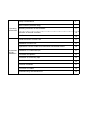
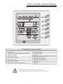
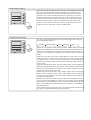
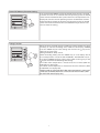
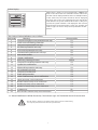
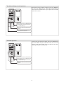
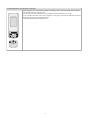
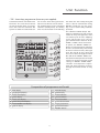
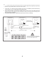
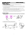
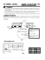
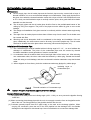
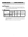
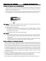
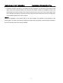
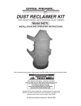
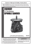
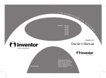
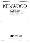
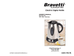
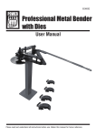
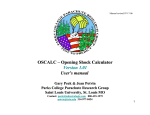
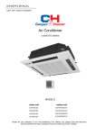
USER'S MANUAL
FREE COMBI SERIES
DUCT UNITS
FC-D09AI, FC-D12AI, FC-D18AI
Before use, please read this instruction manual carefully and keep it properly to ensure correct use of this machine.
Operating
Instructions
Instructions
of Unit
Installation
Safety Considerations
3
Wire controller (standard fitting)
4
Operating istructions of wire controller
5
Operation of Remote Controller
10
Unit Function
14
Profile Dimension of Indoor Unit
17
Installation of Indoor Unit
19
Inspection of Level of Indoor Unit,Fabrication of Backwater Elbow
20
Installation of Condensate Pipe
21
Connection of Pipelines
23
Installation of Connecting Pipe
24
Installation of Wire Controller
26
Electrical Installation
27
Connection of Cables
29
Troubleshooting and Maintenance
30
Safety Considerations
Please read this manual carefully before use and operate correctly as instructed in the manual.
1.
You are specially warned to note the two symbols below.:
WARNING!:A symbol indicating that improper operation might cause human death or severe
injuries.
WARNING!:A symbol indicating that improper operation might cause human injury or property
damage.
WARNING!
This unit shall be used in offices, restaurants, residences or similar places.
Please seek an authorized repair station for installation work. Improper installation might cause water leakage,
electric shock or fire.
Please install at a place strong enough to support the weight of air conditioner unit. If not, the air conditioner
unit might fall down and cause human injury or death.
To ensure proper drainage, the drainage pipe shall be correctly installed according to installation instructions.
Take proper measures for heat preservation to prevent condensing. Improper installation of pipes might cause
leakage and wet the articles in the room.
Do not use or store flammable, explosive, poisonous or other dangerous substances beside the air conditioner.
In case of trouble (e.g. burnt smell), please immediately cut off the main power of air conditioner unit.
Keep air flow to avoid shortage of oxygen in the room.
Never insert your finger or any objects into air outlet and inlet grill.
Never plug or unplug the power cable directly to start or stop the air-conditioning unit.
Please take constant care to check if the mounting rack is damaged after long use.
Never modify the air conditioner. Please contact the dealer or professional installation workers for repair or
relocation of the air conditioner.
The appliance shall not be installed in the laundry.
WARNING!:
Before installation, please check the power supply for compliance with the ratings on nameplate. Check the
power safety as well.(Operating by professinal)
Before use, please check and confirm if the cables, drainage pipes and pipelines are correctly connected,
hence to eliminate the risk of water leakage, refrigerant leakage, electric shock or fire.
Main power must be securely earthed to ensure effective grounding of air conditioner unit and avoid the risk
of electric shock. Please do not connect the earthing cable to coal gas pipe, water pipe, lightning rod or
telephone line.
Once started, the air conditioner shall not be stopped at least after 5 minutes or longer; otherwise the oil
return to compressor may be affected.
Do not let the child to operate the air conditioner unit.
Do not operate the air conditioner unit with wet hands.
Please disconnect the main power before cleaning the air conditioner or replacing the air filter.
Please disconnect the main power if to put the air conditioner unit out of use for a long period.
Please do not expose the air conditioner unit directly under corrosive environment with water or moisture.
Please do not foot on or place any goods on air conditioner unit.
After electrical installation, the air conditioner unit shall be energized for electrical leakage test.(Operating by professinal)
If the supply cord is damaged, it must be replaced by the manufacturer or its service agent or a similarly
qualified person in order to avoid a hazard .
An all-pole disconnection switch having a contact separation of at least 3mm in all poles should be connected
in fixed wiring.
The appliance shall be installed in accordance with national wiring regulations.
The temperature of refrigerant circuit will be high, please keep the interconnection cable away from the
copper tube.
3
Wire controller (standard fitting)
Composition of wire controller
8
Failure status display
9
Sleep st atus display
1
Timing display
2
Fan speed display (Auto, High speed, Medium
speed, Low speed)
10
Mode key
3
Defros ting st atus display
11
Se t temperature incr ease key
4
Energy saving st atus display
12
Se t temperature decr ease key
5
Se t temperature display
13
Fan speed key (fresh air setting)
6
Ambient temperature display
14
Timing key
7
Mode (cooling, dehumidifying,fan, heating, auto)
15
ON/OFF key
• Never install the wire controller in a place where is water leakage.
• Avoid bunping, throwing, tossing or frequently opening the wire controller.
4
Oper ating istructions of wire controller
Turning ON/OFF unit
Pr ess t he ON/OFF ke y, then the unit shall star t up. Pr ess t he ON/OFF
key again, then the unit shall shut off.
Fan contr ol (the figur es show the r elevant display ar eas)
If the fan control key is prssed consecutively, the fan speed shall changes
as per t he following sequence:
Low speed
Medium speed
Hight speed
Auto
In the dehumidifying mode:he
t fan speed shall be automatically se t as
low.
Temperatur e setting
Pr ess the temperature seting key ( ) to increase the set temperature;
press the temperature setting key ( ) to decrease the set temperature
(when pressing the keys once, the temperature shall increase or decrease by 1 °C). NOTE: key lock function: when the ( ) and ( ) key ar epressed
simultaneously for 5 second, the set temperature indicating ar ea shall
display “EE” and all keys response shall be shut off; press the two keys
simultaneously for 5 second again, the key lock function shall be released. When the wire controller is locked by remote monitor or centralized
controller, the keys of the wire controller and the signal of the remote
controller ar e all locked and invalidated, and then the set temperature
indicating ar ea shall display “CC”. Range of temperature setting under
various modes:
Heating: 16 °C ~30 °C • Cooling: 16 °C ~ 30 °C
Dehumidifying:16 °C ~ 30 °C •
Fan: No temperature se tting function
5
Sleep function setting
When the controller functions under cooling or dehumidifying mode and
if the unit runs for one hour after the sleep key is pressed, the set temperature shall increase by 1, and the set temperature shall increase by
another 1 after 2 hours and the unit shall run as per the increased set
temperature. When the controller functions under heating mode and if
the unit runs for one hour after the sleep key is pressed, the set temperature shall decrease by 1, and the set temperature shall decrease by
another 1 after 2 hours and the unit shall run as per the decreased set
temperature. Fan mode does not have sleep function.
Operating Mode Setting
this key is pressed consecutively, the operating mode shall change as
per the following sequence:
Cooling
Dehumidifying
Fan
Heating
Auto
When the unit operates under “Cooling” mode, “COOL” shall be displayed.
Now the set temperature must be lower than the ambient temperature.
Now if the set temperature is higher than the ambient temperature, the
unit shall not produce cooling effect but shall only operate under Fan
mode.
When the unit operates under “Dehumidifying” mode, “DRY” shall be
displayed. Now the interior fan shall operate in the manner of low speed
air supply within a certain range of temperatures. The dehumidifying
effect of this mode is better than that of the Cooling mode and saves
more energy.
When the unit operates under “Heating” mode, “HEAT” shall be displayed.
Now the set temperature must be higher than the ambient temperature;
Now if the set temperature is lower than the ambient temperature, the
heating function shall not be started.
When the unit operates under “Fan” mode, “FAN” shall be displayed.
When the unit operates under “Auto” mode, “AUTO” shall be displayed
and the unit shall adjust its operating mode automatically according to
the ambient temperature.
When the unit operates under Heating mode and the outdoor temperature is low and the humidity is high, frost shall produce at the outdoor
unit. Now the heating efficiency shall be decreased. When frosting happens, the controller shall automatically start to defrost, and “DEFROST”
shall be displayed.
Note: Cooling only type unit does not have heating mode and when energy saving is set the Auto mode shall be invalidated.
6
Timing Setting
When the unit is shut off, timing start can be set; After the unit is started up, timing shutoff can be set. After the “TIME” key is pressed, the unit
enters the timing set status and the word “TIME” flashes on the display.
Now user can press ( ) or ( ) key to increase or decrease the set time.
Press the “TIME” key again and then the timing shall go into effect. Now
the unit starts to count the time passed. When the unit is under timing
status, you can cannel timing set by pressing the “TIME” key.
The range of set time is between 0.5 to 24 hours.
Energy Saving Setting
When the unit is shut off, press the “FAN” key and the ( ) simultaneously for 5
consecutive seconds to activate the energy saving setting menu. Now “SAVE SET”
and “COOL” are displayed (In case it is the first time to set energy saving, the initial valve shall be displayed: 26 . The lower limit of temperature shall be displayed
on the set temperature and the temperature value under setting shall flash. Set
the lower limit of cooling temperature using the ( ) key or the ( ) key (the lower
limit temperature can be selected from the range between 16-30). Press the
“ON/OFF” key to confirm the setting; Also use the ( ) key or the ( ) key to set the
upper limit of temperature and the temperature value shall flash on the ambient
temperature area (OUT ENV area) (the upper limit temperature can be selected
from the range between 16-30). Press the “ON/OFF” key to confirm the setting.
Please pay attention that the upper limit temperature must be higher than the
set lower limit temperature; Otherwise the system shall regard the higher temperature as the upper limit temperature and the lower one as the lower limit
temperature. Press the “MODE” key to complete the energy saving setting for
the modes of cooling and dehumidifying and turn to the energy saving setting for
the heating mode (Cooling only unit does not have this function). Now the LCD
displays “SAVE SET” and “HEAT”. After setting is completed, press the “FAN” key
and the ( ) key simultaneously for 5 consecutive seconds to exit the setting of
energy saving. After the energy saving setting interface is activated, the system
shall exit the interface if there is no any operation within 20 minutes after the
last key input, and the normal shutoff status interface shall be displayed. After
the above settings are completed, the system shall display “SAVE”. Now the set
temperature shall not exceed the temperature range of the energy saving setting before. For example, the lower cooling limit is set as 23 °C and the upper
cooling limit is set as 27°C for the energy saving temperature setting in Figure 9,
so the cooling temperature can only be selected from the range of 23 °C to 27°C
by using the remote controller or the wire controller later. If the upper limit temperature is the same as the lower limit temperature, the system can only operate at such temperature under relevant modes. Remove of energy saving setting:
To remove the energy saving setting after it takes into effect, you can press the
“FAN” and the ( ) key simultaneously for 5 consecutive seconds when the unit is
shut off. But the value set before will not be cleared but as the initial set temperature for the next energy saving setting. After the unit is disconnected to power
supply, the energy saving setting shall be stored. The setting still functions when
the unit is connected to power supply again. If the energy saving mode is set, the
sleep mode and the auto mode shall be invalidated
.
7
Power-fail Memory Function Setting
Press and hold the “MODE” key for 10 seconds when the unit is shut off
to switch set values so as to decide if the unit operating status or shutoff
status shall be memorized after a power fail. If the set temperature area
displays 01, it means the unit operating status or shutoff status shall be
memorized after a power fail; 02 means the operating status or shutoff
status shall not be memorized. Press the “ON/OFF” key to store the set
value and exit the setting.
Debug Function
When the unit is shut off, press the “FAN” key and the “SLEEP” key simultaneously to activate the debug menu. Now the LCD displays “DEBUG”.
Press the “MODE” key to select setting item and use the ( ) key or the
( ) key to set actual valve.
Setting of Ambient Temp. Sensor
Under the debug mode, press the “MODE” key so as to display “01” on
the set temperature area (at the left of “DEBUG”). The OUT ENV area (at
the right of “DEBUG”) displays setting status. Now use the ( ) key or the
( ) key to select from the following two settings:
The indoor room temperature is measured at the air intake (Now the
OUT ENV area displays 01).
The indoor room temperature is measured at the wire controller ( Now
the OUT ENV area displays 02).
Heating mode or Auto mode the indoor room temperature is measured
at the wire controller,otherwise is measured at the air intake ( Now
the OUT ENV area displays 03).
8
Failure Display
When there is failure in the unit operation, “ERROR” will
flash on the LCD of the wire controller and the code of failure will also be displayed. When there are multiple failures
at the same time, the codes of failures will be displayed
one after one on the wire controller. The first digit of the
code denotes the system number. When there is only one
system, the system number is not displayed. The last two
digits denote the detailed failure code. For example, the
code in Figure 13 means low pressure protection of compressor.
The Codes of Failure Definitions are as Follows:
Meaning
Fault code
Compressor high pressure protection unit stop
1
Indoor unit anti-freezing protection
2
3
Low-pressure protection unit stop
4
Air exhaust protection unit stop
5
Over current protection unit stop
6
Communication malfunction unit stop
Unit modes conflict
7
Jumper malfunction
8
Defrosting /Heating oil return
9
10
11
12
13
14
15
16
17
18
19
20
21
22
Compressor overload protection unit stop
System Unit malfunction
IPM modular protection unit stop
PFC protection unit stop
Compressor malfunction
Water spill protection
Indoor ambient temp. sensor malfunction
Indoor pipe temp. sensor malfunction
Outdoor ambient temp. sensor malfunction
Outdoor pipe temp. sensor malfunction
Outdoor air exhaust temp. sensor malfunction
E2 PROM Error
Wire controller ambient temp. sensor malfunction
Wire controller
E1
E2
E3
E4
E5
E6
E3
E3
defrost
E5
F2
E5
E5
E9
E9
F0
F1
F3
F2
F4
E3
F5
E5 Material Malfunction Will Be Showed By The Indicator Light On The Mother Board Of Outside Unit
• The “EH” failure is displayed, cut off the power supply of the unit immediately,
and only ask professional serviceman to repair the unit!
9
Operation of Remote Controller
Precautions:
• Ensure there is no obstacle between the remote controller and the signal receiving window of the air conditioner.
• The distance able to receive the signal of the remote controller can be as far
as 8 meters.
• Never drop or throw at will the remote controller.
• Never let any liquid enter the remote controller. Avoid direct sunshine over the
remote controller. Do not place the remote controller in an extremely hot place.
Press FAN button, set fan speed
Press TEMP, button
set suitable TEMP
Pr ess MODE button to set operation
mode
Plug in, press ON/OFF
button then air conditioner is turned ON
10
Cooling Mode Operation
Connect the unit to power supply. Press the “ON/OFF”key.
Press the “MODE” key to select “Cooling” mode. Use the
“Temperature” key to adjust the set temperature for the
room.
a) After the unit is connected to
power supply, the air conditioning unit
shall enter the operating status if you
press the ON/OFF key
b) Press the mode key and select the
(
) mode
c) Press the temperature key and set
the temperature as required
Heating Mode Operation
a) After the unit is connected to
power supply, the air conditioning unit
shall enter the operating status if you
press the ON/OFF key
Connect the unit to power supply. Press the “ON/OFF”key.
Press the “MODE” key to select “Heating” mode. Use the
“Temperature” key to adjust the set temperature for the
room.. Under the heating mode, the unit has the functions
of preventing cold air supply and supplying remaining heat.
After the startup of the compressor, the indoor fan shall
start operation when the evaporator temperature is larger
or equals 35 or after the unit has be started for 5 seconds
(the indoor environment temperature is larger or equals 20℃),
or after the unit has be started for 90 seconds(the indoor
environment temperature is less 20℃), so as to avoid supply
of cold air shortly after the unit is started.After the stop of
the compressor, the indoor fan shall stop operation after
supplying air for 120 seconds.
b) Press the mode key and select the
(
) mode
c) Press the temperature key and set
the temperature as required
11
DRY (Dehumidifying) Mode Operations
Connect the unit to power supply. Press the “ON/OFF”
key. Press the “MODE” key to select “DRY (Dehumidifying)”
mode. Use the “Temperature” key to adjust the set temperature for the room.
a) After the unit is connected to
power supply, the air conditioning unit
shall enter the operating status if you
press the ON/OFF key
b) Press the mode key and select the
( ) mode
c) Press the temperature key and set
the temperature as required
Fan Mode Operation
Connect the unit to power supply. Press the “ON/OFF”key.
Press the “MODE” key to select “FAN” mode. The unit shall
operate under “FAN” mode. Press the “FAN” key to select
from high, medium and low speed.
a) After the unit is connected to
power supply, the air conditioning unit
shall enter the operating status if you
press the ON/OFF key
b) Press the mode key and select the
( )mode
12
Loading Batteries Into Remote Controller
• After batteries are installed, the display shall display icons and letter codes of all functions.
• The life of batteries is about 1 year.
• Do not mix new and old batteries or mix different types of batteries in usage
• If the remote controller shall not be used for a long time, take out the batteries to avoid
liquid leakage and any subsequent failure.
• Load two “AAA” batteries (Accessories)
13
U nit Function
• 7DP - Seven days programmer (Accessory not supplied)
Centralized Control and Week Timer
Functions: The centralized controller and the weekly timer are integrated in the same wire controller. The
system has both the centralized con-
trol and the week timing functions.
Up to 16 sets of units can be controlled simultaneously by the centralized
controller (weekly timer). The weekly
timer has the function of invalidating
the lower unit. The weekly timing function is able to realized four timing
ON/OFF periods for any unit every
day, so as to achieve fully automatic
operation.
This WEEKLY TIMER adopts 485
mode to communicate with manual
control of every duct type unit, and it
can control up to 16 units. Adopting
2-core twisted-pair wire, the longest communication distance of this
TIMER is 1200m. After connected
to power, the WEEKLY TIMER can
display all connected units (sequence
of unit is determined by code switch
of manual control of every duct type
unit). On and off of every duct type
unit can be done through the Timer
On / Off of this WEEKLY TIMER, and
the button shield operation of manual
control can be done through shield
setting on WEEKLY TIMER. Mode
selection and temperature adjustment and other operations are done
through the manual control at every
unit.
Composition of programmer wall week
1
2
3
4
5
6
7
8
9
10
11
12
13
14
15
16
17
Unit dispaly
Single/group display
Timer week display
Timer display
Timer state display
Timer time period display
Timer ON/OFF time display
Unit on display
14
Unit off display
Clock display
Confirm button
Increase button
Decrease button
Cacel/delete button
Single/group button
Timer/time button
ON/OFF button
Note:
2
1. For upper unit checks 16 lower units consecutively, there will be no more than 16 seconds delay when setting works till unit responds.
Please let us know your requirement before your placing the order, for this WEEKLY TIMER will only be prepared when customer orders
(communication joint with WEEKLY TIMER on manual control had been prepared).
1.
Press ▲ or ▼ to select the unit that needed to be control. It is available to control several units by
Group Control (1~16), or control single unit by Single Control.
2. When selected a certain or several units by Single Control or Group Control, Timer setting and On/off
setting can be set. Timer setting can set 4 on/off times in a day in one week; and on/off setting can be
done by pressing on/off button.
3. Connection between WEEKLY TIMER and manual control is shown as following:
Week timer
Manual control
LCD
LCD
Telephone wire box
Manual control
16 units in max
LCD
Telephone wire box
Telephone
wire box
Power
supply
Twisted wire with crystal joint
Longest distance 1200 m
On Off
Power
Corresponding relation between code
switch and sequence of unit (NOTE: putting code switch to ON means 0)
15
Unit Function
Setting of Indoor Room Sensor and Checking of Outdoor Ambient Temperature
2. Setting of Double Indoor Room Sensors
This series of ducted air-conditioning unit has two indoor room sensors. One is located at the air intake of
the indoor unit and the other one is located inside the wire controller.
User can select one from the two indoor room sensors on the basis of the engineering requirement
(Refer to the section of wire controller instructions for detailed operation. The default indoor room sensor
is the one located at air intake.)
Indoor Room Sensor A
Indoor Room Sensor B
Fig.1
16
Instructions of Unit Installation
Profile Dimensions of Indoor Unit
Profile Dimensions of Indoor Unit
E le c tric B o x
L iq u id P ip e
G a s P ip e
I
A ir In ta ke
A ir In ta k e
Be suit for:
F
FC-D09AI
FC-D12AI
FC-D18AI
Fig.2
17
D ra in a g e P ip e
Instructions of Unit Installation
Profile Dimensions of Indoor Unit A
B
C
D
E
F
G
H
I
J
856
571
515
790
913
680
750
100
172
220
1/4
932
430
738
894
1012
736
738
125
207
266
1/4
Dimension Requirement of the Installation Space of Indoor Unit
Be suit for:
FC-D09AI
FC-D12AI
FC-D18AI
Nut with
Washer
Nut Spring
Washer
Fig.3
Warning: The height of installation for the indoor unit should be 2.5m above.
18
3/8
1/2
1/2
Drainage
Pipe (Outer
Diameter × Wall Thickness)
Item
Connecting
Pipe (Gas
Pipe)
Model
FC-D09AI
FC-D12AI
FC-D18AI
Connecting
Pipe (Liquid
Pipe)
Profile Dimensions of Indoor Unit
ф20×1.5
ф30×1.5
Unit Installation Instructions
Installation of Indoor Unit
Installation of Indoor Unit
1. Selection of Installation Site
(1) Ensure the top hanging piece has strong strength to withstand the weight of the unit.
(2) The drainage pipe has convenient flow of water.
(3) There is no obstacle blocking the air intake and exhaust outlet, so as to ensure sound air circulation.
(4) The installation spaces required by the drawing must be ensured, so as to provide enough space for
the service and maintenance.
(5) The installation site must be far away from heat source, leakage of inflammable gas or smoke.
(6) The indoor unit is of ceiling mount (indoor unit is hidden inside the ceiling).
(7) The indoor and outdoor units, the power cable and the connecting electrical lines must be at least 1
meter from any TV set or radio. This is to avoid image interference or noise of the TV set or radio.
(Even if the distance is 1 meter, noise can also exist if there is strong electric wave.)
2. Installation of Indoor Unit
(1) Insert a M10 expansion bolt into the hole. Drive a nail into the bolt. Refer to the profile dimensions
drawing of the indoor unit for the distance between the holes. Refer to Figure 4 for the installation
of the expansion bolt.
Ceiling-mount
Screw
Fig. 4
Air-conditioning Unit
Hanger
Fig. 5
Screw
螺杆
Hanger
挂钩
Nut
螺母
I
mm
(2) Install the hanger onto the indoor unit as Figure 5 shows.
(3) Install the indoor unit at the ceiling as Figure 6 shows.
Air Supply
送风
Air Intake
I放大
I Enlargement
Fig. 6
19
Unit Installation Instructions
Inspection of Level of Indoor Unit,
Fabrication of Backwater Elbow
Precautions:
1. The preparation of all pipes (connecting pipes and drainage pipes) and cables (connecting lines of
wire controller, indoor unit and outdoor unit) must be ready before the installation, so as to achieve
smooth installation.
2. Drill an opening on the ceiling. Maybe it is required to support the ceiling to ensure the evenness of it
and avoid the vibration of it. Consult with the user or a construction company for details.
3. In case the strength of ceiling is not enough, use angle iron sections to set up a beam support. Place
the unit at the beam and fix it.
Level Check of the Indoor Unit
After the indoor unit is installed, it is required to check the level of the whole unit. The unit must be placed
horizontally, but the condensate pipe shall be installed obliquely, so as to facilitate the drainage of
condensate.
Level Instrument
i
Air Intake
Air Supply
Condensate
Drainpipe
Enlarged View
Condensate Drainpipe
As the inside of the unit is in
the negative pressure status, it
is required to set up a
backwater
elbow.
The
requirements is:
A=B≥P/10+20(mm)
P is the absolute pressure
inside the unit. The unit of the
pressure is Pa.
Fig. 7
Installation of Rectangular Air Pipe
Air Supply
Air Intake
No.
1
Ceiling Mount
Air Supply
2
3
Air Intake
4
Fig. 8
20
Name
Hanger
Air Intake
Pipe
Canvas Air
Pipe
Air Intake
No. Name
Filter
5
6
7
Main Air
Supply Pipe
Air Supply
Outlet
Unit Installation Instructions
Installation of Condensate Pipe
Cautions:
The air supply pipe, the air intake pipe and the fresh air pipe must be covered with a layer of
thermal insulation, so as to avoid thermal leakage and condensation. Firstly apply liquid nail on
the pipes, then attach the thermal insulation cotton with a layer of tinfoil. Use the liquid nail cover
to fix it. Lastly use tinfoil adhesive tape to carefully seal the joints; other good thermal insulation
materials can also be used.
The air supply pipes and the air intake pipes shall be fixed to the prefabricated boards of the
ceiling by using iron supports. The joints of the pipes must be sealed by glue so as to avoid
leakage.
The design and installation of air pipes must be in conformity with the relevant state engineering
criteria.
The edge of the air intake pipe must be at least 150mm away from the wall. The air intake must
be covered with filter.
Silencing and shock absorption shall be considered in the design and installation of the air
pipes. Additionally, the noise source must be far away from where people stay. The air intake
shall not be located above the place where users stay (offices and rest places, etc.).
Installation of Condensate Pipe
(1) The condensate pipe shall be installed with an inclining angel of 5~10°, so as to facilitate the
drainage of condensate. The joints of the condensate pipe must be covered by thermal
insulation materials to avoid generation of exterior condensate.
(2) A condensate outlet is located at both the left and right sides of the indoor unit. After selecting
one condensate outlet, the other outlet shall be blocked by rubber plug. Bundle the blocked
outlet with string to avoid leakage, and also use thermal insulation materials to wrap the blocked
outlet.
(3) When shipped out from factory, both the condensate outlets are blocked by rubber plugs.
冷凝水管
Insulating Layer of
保温层
Condensate Pipe
管盖
Cover board
Figure 9
Thermal Insulation of Condensate Pipe
Caution: The joint of condensate pipe must not have leakage.
Design of Drainage Pipeline
(1)The pipeline must always have an inclining angle (1/50~1/100), so as to prevent the pipeline froming
water flow.
(2) When connecting the drainage pipe with the unit, do not apply excessive force to the pipeline at the
side of the unit. The fixing position of the pipeline shall be near the unit.
(3) Purchase general-purpose hard PVC pipe locally to be used as the drainage pipeline. When
carrying out connection, place the end of the PVC pipeline into the drainage hole. Use flexible
drainage tube and tighten it with thread loop. Never use adhesive to connect the drainage hole
21
Unit Installation Instructions
Installation of Condensate Pipe
and the flexible drainage tube.
(4) When the laid drainage pipe is used for multiple units, the common pipe shall be about 100mm
lower than the drainage outlet of each set of unit. A pipe with thicker wall shall be used for such
purpose.
Testing of Drainage System
(1) After the electrical installation is completed, carry out the testing of the drainage system.
(2)
During the test, check if the water correctly flows through the pipelines. Carefully
observe the joints to ensure that there is no leakage. If the unit is to be installed in a new
house, carry out testing before decorating the ceiling.
(3)
Selection of Connecting Pipe
Item
Size of Fitting Pipe
(Inch)
Gas Pipe
Model
FC-D09AI
3/8
FC-D12AI
FC-D18AI
1/2
Liquid
Pipe
1/4
Max.
Pipe
Length
(m)
Max. Height
Difference
between
Indoor Unit
and Outdoor
Unit m
Amount of Additional
Refrigerant to be
Filled (For Extra
Length of Pipe)
20
15
30g/m
Note:1 The standard pipe length is 5m. When the length (L) of the connecting pipe is less than or equals 5m,
there is no need to add refrigerant. If the connecting pipe is longer than 5m, it is required to add
refrigerant. In the above table, the amounts of refrigerant to be added for the models are listed for each
additional meter of pipe length.
2. The pipe wall thickness shall be 0.5-1.0 mm and the pipe wall shall be able to withstand the pressure of
6.0 MPa.
3.The longer the connecting pipe, the lower the cooling effect and the heating effect.
22
Instructions of Unit Installation
Connection of Pipelines
Connection of Pipeline
1. Align the flared end of the copper pipe with the center of the thread joint. Manually tighten the
flared end nut.
2. Use torque spanner to tighten the flared end nut until the spanner clatters (Figure 10).
Fitting Pipe for
Indoor Unit
Flaring Nuts Fitting Pipe
Spanner
Torque wrench
Fig.10
The following table describes the torques for tightening nuts of different pipe diameters.
Pipe Diameter
1/4〞(Inch)
3/8〞(Inch)
1/2〞(Inch)
Tightening Torque
15-30 (N·m)
35-40 (N·m)
45-50 (N·m)
23
Instructions of Unit Installation
Installation of Connecting Pipe
Installation of Protective Layer of Connecting Pipe
1.To avoid generation of condensate on the connecting pipe and avoid leakage, the big pipe and the
small pipe of the connecting pipe must be covered by thermal insulation materials, be bundled by
adhesive tape, and be isolated from air.
2.The joint connecting to the indoor unit must be wrapped by thermal insulation material. There shall
be no gap between the connecting pipe joint and the wall of the indoor unit. Refer to Figure 11.
No Gap
无间隙
Fig.11
Caution: After the pipes are wrapped by protective materials, never bend the pipes to form very
small angle, and otherwise the pipes may crack or break.
3.Use adhesive tape to wrap the pipes:
(1) Use adhesive tape to bundle the connecting pipe and the cables together. To prevent
condensate from overflowing out from the drainage pipe, separate the drainage pipe firm the
connecting pipe and the cables.
(2) Wrapped pipe must be fixed to wall using pipe clamps.
Caution:
(1) Do not wrap the protective tape too tight, and otherwise the efficiency of thermal insulation
may be decreased. Ensure that the condensate drainage flexible tube is separate from the
bundled pipes.
(2) After the protective work is completed and the pipes are wrapped, use seal material to block
the hole in the wall, so as to prevent rain and wind from entering the room.
Position and Method of Installing Wire Controller
1. One end of the control wire of the manual controller is connected with main board of electric box of
indoor unit inside, it should be tightened by wire clamp, the other end should be connected with the
manual controller (installation sketch map as shown in below). The control wire be used for the
indoor unit and manual controller, which is the special communication wire, the length is 8 meters,
the material be adopted for the control wire should be metallic substance. The manual controller
could not be disassembled and the communication wire be used for the manual controller should not
be changed by users optionally, the installation and maintenance should be carried out by the
professional personnel.
2. First select an installation position. According to the size of the communication line of the wire
controller, leave a recess or a embedded wire hole to bury the communication line.
3. If the communication line between the wire controller and the indoor unit is
surface-mounted, use 1# metallic pipe and make matching recess in the wall (refer to Figure 11);
24
Instructions of Unit Installation
Installation of Connecting Pipe
4. No matter if surface mounting or concealed mounting is selected, it is required to drill 2 holes (in the
same level) which distance shall be the same as the distance (60mm) of installation holes in the
bottom plate of the wire controller. Then insert a wood plug into each hole. Fix the bottom plate of the
wire controller to the wall by using the two holes. Plug the communication line onto the control panel.
Lastly install the panel of the wire controller.
Caution:
During the installation of the bottom plate of the wire controller, pay attention to the direction of the
bottom plate. The plate’s side with two notches must be at the lower position, and otherwise the panel of
the wire controller cannot be correctly installed.
25
Instructions of Unit Installation
metallic pipe
Installation of Wire Controller
metallic pipe
1
Figure 12 Surface
Mounting of Cable
Figure 13 Concealed
mounting of Cable
No.
1
2
3
4
Caution:
2
3
Figure 14 Schematic Diagram of Installation
Name
Wall Surface
Bottom Plate of Wire Controller
Screw M4X10
Panel of Wire Controller
1. The communication distance between the main board and the wire controller is 8 meters.
2.The wire controller shall not be installed in a place where there is water drop or large amount of
water vapor.
26
4
Instructions of Unit Installation
Electrical Installation
Caution: Before installing the electrical equipment, please pay attention to the following matters
which have been specially pointed out by our designers:
(1) Check to see if the power supply used conforms to the rated power supply specified on the
nameplate.
(2)
The capacity of the power supply must be large enough. The section area of fitting line in the
room shall be larger than 2.5mm 2 .
P
(3)
P
The lines must be installed by professional personnel.
An electricity leakage protection switch and an air switch with gap between electrode heads larger than
3mm shall be installed in the fixed line.
1.
Connection of signal wire
(1)
Use wire stripper to strip the insulation layer (25mm long) from the end of the signal wire.
(2)
Remove the screw at the terminal board of the air-conditioning unit.
(3)
Use pliers to bend the end of the signal wire so that a loop matching the screw size is formed.
(4)
Put the screw through the loop of the signal wire and fix the loop at the terminal board.
2.
(1)
Connection of multiple twisted wires
Use wire stripper to strip the insulation layer (10mm long) from the end of the multiple twisted
wires.
(2)
Remove the screw at the terminal board of the air-conditioning unit.
(3)
Use crimping pliers to connect a terminal (matching the size of the screw) at the end of the
multiple twisted wires.
(4)
Put the screw through the terminal of the multiple twisted wires and fix the terminal at the
terminal board.
Warning:
If the power supply flexible line or the signal line of the equipment is damaged, only use special
flexible line to replace it.
1.
Before connecting lines, read the voltages of the relevant parts on the nameplate. Then carry
out line connection according to the schematic diagram.
2.
The air-conditioning unit shall have special power supply line which shall be equipped with
electricity leakage switch and air switch, so as to deal with overload conditions.
3.
The air-conditioning unit must have grounding to avoid hazard owing to insulation failure.
4.
All fitting lines must use crimp terminals or single wire. If multiple twisted wires are connected
to terminal board, arc may arise.
5.
All line connections must conform to the schematic diagram of lines. Wrong connection may
cause abnormal operation or damage of the air-conditioning unit.
6.
Do not let any cable contact the refrigerant pipe, the compressor and moving parts such as fan.
7.
Do not change the internal line connections inside the air-conditioning unit. The manufacturer
shall not be liable for any loss or abnormal operation arising from wrong line connections.
Power Cable Connection:
1. Air-conditioning unit with single-phase power supply
(1) Remove the front-side panel of the outdoor unit.
(2) Pass the cable though rubber ring.
(3) Connect the power supply cable to the “N(1),(2),(3)” terminals and
the grounding screw on the metal electric box.
27
Instructions of Unit Installation
(4 )
Electrical Installation
Use cable fastener to bundle and fix the cable.
Connection of Signal Line of Wire Controller
1.
Open the cover of the electric box of the indoor unit.
2.
Pull the signal cable of the wire controller through the rubber ring.
3.
Plug the signal line of the wire controller onto the 4-bit pin socket at the circuit board of the indoor unit.
(CN10 of the wire controller connect with CN3 of the indoor unit)
4. Use cable fastener to bundle and fix the signal cable of the wire controller.
28
Instructions of Unit Installation
Connection of Cables
Cable Connecting Diagram of Unit
Schematic Diagram of Unit Line Connection:
FC-D09AI
FC-D12AI
FC-D18AI
29
Instructions of Unit Installation
Troubleshooting and Maintenance
If your air-conditioning unit suffers from abnormal operation or failure, please first check the
following points before repair:
Failure
The unit cannot be started.
The unit operates for a while
and then stops.
1.
2.
3.
4.
1.
2.
3.
1.
2.
Poor cooling effect.
3.
4.
5.
6.
7.
1.
2.
3.
Poor heating effect
4.
5.
6.
Possible Reasons
The power supply is not connected.
Electrical leakage of air-conditioning unit
causes tripping of leakage switch.
The operating keys are locked.
The control loop has failure.
There is obstacle in front of the condenser.
The control loop is abnormal.
Cooling operation is selected when the
outdoor ambient temperature is above 43 .
The air filter is dirty or blocked.
There is heat source or too many people
inside the room.
The door or window is open.
There is obstacle at the air intake or outlet.
The set temperature is too high thus cooling
is hindered.
There is refrigerant leakage.
The performance of room temperature
sensor becomes worse
The air filter is dirty or blocked.
The door or window is not firmly closed.
The set room temperature is too low thus
heating is hindered.
There is refrigerant leakage.
The outdoor ambient temperature is lower
than -5 .
Control line is abnormal.
Note: After carrying out the check of the above items and taking relevant measures to solve the problems
found but the air-conditioning unit still does not function well, please stop the operation of the unit
immediately and contact the local service agency designated by SINCLAIR. Only ask professional
serviceman to check and repair the unit.
Routine Maintenance
Cleaning the Air Filter(Operating by the professional)
(1) Do not disassemble the air filter when cleaning it. Otherwise failure may be caused
(2) If the air-conditioning unit is used in an environment with much dust, you should clean the air
filter frequently (once every two weeks).
Caution: You shall pay attention to the following matters when cleaning the
air-conditioning unit.
1)
Cut off all power supply before contacting the line connecting equipment.
2)
Only clean the air-conditioning unit after the unit is shut off and the power supply is
disconnected. Otherwise electrical shock or injury may be caused.
3)
Do not use water to clean the air-conditioning unit. Otherwise there may be electrical shock.
30
Instructions of Unit Installation
4)
2.
Troubleshooting and Maintenance
Take care when cleaning the air-conditioning unit. Use a steady stepping stand.
Maintenance at the Beginning of Operating Season
Check the air inlet and outlet of the indoor and outdoor units to confirm there is no blockage.
Check to see if the grounding wire is in good condition;(Operating by the professional)
Check to see if the line connection is in good condition;(Operating by the professional)
Check if there is any word displaying on the LCD of the wire controller after connecting the unit
to power supply.
Note: If there is any abnormal condition, ask aftersales personnel to offer guidance.
3.
Maintenance at the End of the Operational Season
(1) When the weather is clear, operate the unit under fan mode for half a day, so as to dry the inside
of the unit.
(2) If not to use the air-conditioning unit for a long time, please cut off the power supply. Now
the words on the LCD of the wire controller shall disappear.
31
ENVIRONMENTAL INFORMATION
This unit contains fluorinated gases with greenhouse effect covered by the Kyoto Protocol.
Maintenance and disposal must be carried out by qualified persons only.
Refrigerant gas R410A, GWP = 1730
EXTRA REFRIGERANT CHARGE
Pursuant to Regulation EC 842/2006 on certain fluorinated greenhouse gases, in case of extra
refrigerant charge, it is compulsory to:
-
Fill in the label accompanying the unit inserting the factory quantity of refrigerant
charge (see the technical label), the extra refrigerant charge and the total charge.
Apply the label next to the technical label applied on the unit. For the split-type air
conditioner apply on the outdoor unit.
This product must not be disposed together with the domestic
waste. This product has to be disposed at an authorized place
for recycling of electrical and electronic appliances.
66162468