1
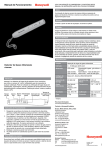
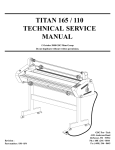
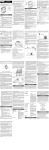
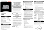
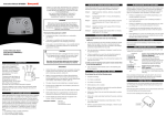
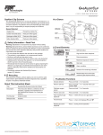
1. WHAT IS CARBON MONOXIDE?
INTRODUCTION
Thank you for purchasing this alarm which is designed to detect the presence of carbon
monoxide (CO) gas. This manual contains information on the installation and the operation
of the SF340 modular carbon monoxide alarm.
Carbon monoxide is a highly poisonous gas which is released when fuels are burnt. It is
invisible, has no smell and no taste, therefore it is very difficult to detect with the human
senses.
The following symptoms are related to carbon monoxide poisoning and should be discussed
with ALL members of the household:
Mild exposure:
Slight headache, nausea, vomiting, fatigue (often
described as “flu-like” symptoms)
Medium exposure:
Severe throbbing headache, drowsiness,
confusion, fast heart rate.
Extreme exposure:
Unconsciousness, convulsions, cardiorespiratory
failure, death.
Potential danger areas in your hom e
G as, coal
or w ood
fire
Clogged
chim ney
or flue
THIS ALARM SHOULD ONLY BE
INSTALLED BY A COMPETENT PERSON
ALL ELECTRICAL WIRING SHOULD BE
INSTALLED IN ACCORDANCE WITH THE
CURRENT WIRING REGULATIONS OF THE
INSTITUTE OF ELECTRICAL ENGINEERS
2. WHAT ARE THE SYMPTOMS OF CARBON MONOXIDE POISONING?
Boiler
or
heater
Car
fum es
from
garage
Water
heater
Portable
cooking
equipm ent
used in
enclosed
areas
Portable
gas or
paraffin
heater
Kitchen
cooker
A dangerous quantity of carbon monoxide can occur if one or more of the following
conditions exists:
1.
An appliance is faulty or badly maintained.
2.
A flue is partially or totally blocked.
3.
A room is not adequately ventilated.
Excessive spillage or reverse venting of fuel burning appliances caused by
outdoor ambient conditions such as:
i.
Wind direction and/or air velocity; including high gusts of wind. Heavy
air in the vent pipes(cold humid air with extended periods between cycles)
ii.
Negative pressure differential resulting from use of exhaust fans.
iii.
Simultaneous operation of several fuel burning appliances competing
for limited internal air.
iv.
Flue connections breaking loose from clothes dryers, water heaters or
boilers.
v.
Obstructions in or unconventional flue designs which can amplify the
above situations.
Ideally you should have an alarm in or near every room which contains a fuel-burning appliance.
However, if you have more than one appliance but only one alarm, you should take the
following into consideration when deciding where best to put the alarm:
·
If there is a fuel burning appliance in a room where people sleep, you
should put the alarm in that room.
·
If there is a fuel burning appliance in a room you use a lot such as a
sitting room, you should put the alarm in that room.
·
If you live in a bed-sit put the alarm as far away from the cooking
appliance as possible, but near to the room where you sleep.
Do not place the alarm in the following areas:
· Outside the building.
· In or below a cupboard.
· In a damp or humid area.
·
If the fuel burning appliance is in a room not normally used (e.g. a boiler
room) put the alarm just outside the room so you will be able to hear it.
· Directly above a sink or cooker.
· Next to a door or window or anywhere it could be affected by drafts.
· Where the airflow to the alarm could be obstructed by curtains or furniture.
· Where dust or dirt could collect and block the sensor.
Extended use of unvented fuel burning devices.
· Where the temperature could drop below -5ºC or rise above 40º C.
3.
Temperature inversions which can trap exhaust gases near the ground.
· Where it could be easily knocked or damaged.
4.
A car running in an open or attached garage near a home.
· Within 1.5m (5 feet) of any cooking appliance.
This manual covers the following models:
SF340E
SF340F
SF340G
SF340H
SF340J
CARBON MONOXIDE ALARM
RETAIN THE MANUAL IN A SAFE PLACE
FOR FUTURE REFERENCE.
5. WHERE NOT TO PUT THE ALARM
2.
SF340M
CAREFULLY READ AND UNDERSTAND THE CONTENTS OF
THIS INSTRUCTION MANUAL BEFORE USING THE ALARM.
1.5m
(5 )
(m in)
3. IN WHICH ROOM SHOULD I PUT THE ALARM?
230V, 50Hz Standard Model
230V, 50Hz Output Model (for relay and interconnect feature)
230V, 50Hz Lead & Plug Model
12Vdc Standard Model
12/24Vdc Output Model (for relay and interconnect feature)
SPECIFICATION
TESTING YOUR ALARM
A green power light indicates power is supplied. The alarm should be tested weekly by pushing
and holding the test button on the front of the unit. The alarm signal should sound. If relay
models are in use or units are interconnected please be aware that the relay function will be
activated upon test.
Each of the models above comes complete with:
Model SF340 series
1.85m
(6 )
(m in)
Under normal operating conditions, in a room where fuel burning appliances are well maintained
and correctly ventilated, the amount of carbon monoxide released by the appliances is not
dangerous.
1.
Issue C 09/99
Carbon monoxide has a similar density to warm air. To ensure the most effective use is made
of the alarm it should be fitted at least 1.5m(5’) above floor level and at least 1.85m (6’) from
the fuel burning appliance.
ALARM
Many reported cases of carbon monoxide poisoning indicate that while victims are aware
they are not well, they become so disorientated that they are unable to save themselves by
either exiting the building or calling for assistance. It is also important to note that young
children and pets may be the first to be affected.
The following conditions can result in transient carbon monoxide situations:
User Manual
2102M0610
4. WHERE SHOULD I PUT THE ALARM?
Carbon Monoxide Sensor Module including battery back-up and
electrochemical gas sensing system.
WARNING
Actuation of your carbon monoxide(CO) alarm indicates the presence of
carbon monoxide(CO) which can KILL YOU.
Gas Detected:
Detection Principle:
Alarm Indication:
CARE AND MAINTENANCE OF ALARM
Alarm Levels:
The outside casing of the alarm should be wiped occasionally with a cloth. Ensure that the
holes on the front are not blocked with dirt and dust. DO NOT USE CLEANING AGENTS,
BLEACH OR POLISH.
Supply Voltage Range:
IMPORTANT
THIS CARBON MONOXIDE ALARM MAY NOT PROTECT PEOPLE WHO
ARE AT SPECIAL RISK BY REASON OF AGE, PREGNANCY OR MEDICAL
CONDITION. THESE INDIVIDUALS MAY CONSIDER USING WARNING
DEVICES WHICH PROVIDE AUDIBLE AND VISUAL SIGNALS FOR CARBON
MONOXIDE CONCENTRATION UNDER 30PPM. IF IN DOUBT PLEASE
CONTACT YOUR MEDICAL PRACTITIONER.
·
A CARBON MONOXIDE ALARM IS NOT A SUBSTITUTE FOR A SMOKE
ALARM OR A COMBUSTIBLE GAS DETECTOR.
·
This carbon monoxide alarm is designed to detect carbon monoxide gas
from any source of combustion including wood, coal, coke, oil, petrol and gas.
Models:
·
Ideally it is recommended that a carbon monoxide alarm should be
installed in or near to every room which contains a fuel burning appliance
such as gas fires, central heating boilers, room heaters, water heaters,
cookers, grills etc
Ensure that the alarm buzzer can be heard by all those who are
intended to hear it.
Seek medical help if it is suspected that a member of the household is
suffering from carbon monoxide poisoning.
IF FURTHER DETAILS ARE REQUIRED THAT DO NOT APPEAR
IN THIS MANUAL PLEASE CONTACT SF DETECTION LTD.
Operating Temperature:
SF340E,F,G,H,J.
Carbon monoxide.
Electro-chemical cell.
Flashing red light and audible alarm.
150ppm
350ppm
Between 10 and 30 minutes.
Within 6 minutes.
(as required by BS7860: 1996)
SF340E,F,G 220/240Vac, 50Hz
SF340H
12Vdc ±10%
SF340J
12Vdc ±10% or 24Vdc ±10%
-5ºC to 40ºC.
Humidity Range:
30 to 90% RH.
Warm-up Time after Initial Switch On:
Instantaneous.
Normal Module Operating Life:
Backup Battery Life when in Alarm:
Dimensions:
Weight:
5 years.
At least 5 days.
170mm x 110 mm x 65mm.
Approximately 575g.
PAY PARTICULAR ATTENTION TO THE SAFETY WARNINGS.
THIS CARBON MONOXIDE ALARM IS NOT:
BE SURE TO PASS THE MANUAL ON TO ANY SUBSEQUENT
USERS OF THE ALARM.
WHEN INSTALLING THIS ALARM
FOR USE BY OTHERS PLEASE
LEAVE THIS MANUAL OR A COPY
WITH THE END USER.
SF Detection Ltd.
4 Stinsford Road, Nuffield Industrial Estate
Poole, Dorset BH17 0RZ
Tel: (01202) 645577 Fax: (01202) 665331
·
·
·
Designed to detect smoke fire or any other gas.
To be seen as a substitute for the proper servicing of fuel-burning appliances
or the sweeping of chimneys.
To be used on an intermittent basis, or as a portable alarm for the spillage of
combustion products from fuel burning appliances or chimneys.
CAUTION
This carbon monoxide alarm is designed for indoor use only. Do not expose to
rain or moisture. Do not knock or drop the alarm. Do not tamper with the
alarm as this could cause electric shock or alarm malfunction. The alarm will
not protect against the risk of carbon monoxide poisoning when the battery
back up is no longer functioning. This alarm will only indicate the presence of
carbon monoxide gas at the sensor. Carbon monoxide gas may be present in
other areas. Do not paint.
DISPOSAL WARNING: Do not dispose of in fire.
PACK CONTENTS:
Models SF340E, SF340F, SF340H, SF340J
will contain:
One alarm,
One Sensor Module (SF340M),
One instruction manual,
One installation kit, consisting of:
Two wall plugs,
Two wall fixing screws,
Two electrical mounting screws.
Model SF340G will contain:
One alarm,
One Sensor Module (SF340M),
One instruction manual,
One installation kit, consisting of:
Two wall plugs,
Two fixing screws,
Two spacers.
GUARANTEE
We guarantee your new gas alarm for five years from the date of purchase and under normal
use and service, to be free from defects in materials and workmanship. During this period we
will at our discretion, repair, replace or refund the price of any part of the alarm which is found
to be defective in either materials or workmanship providing this occurs under normal use
and service. We shall however be under no obligation to repair, replace or refund the price of
units which are found to be defective in any way due to damage, neglect, unreasonable use
or which have been tampered with or found to have been dismantled. Defective units should
be returned, in suitable packaging, along with proof of purchase to SF Detection Limited,
4 Stinsford Road, Nuffield Industrial Estate, Poole, Dorset. BH17 0RZ. An accompanying
letter should clearly state the nature of the problem with the alarm. This guarantee does not
affect your statutory rights.
6. OPERATION OF THE ALARM
8. HOW SHOULD I INSTALL MY ALARM?
TE S T
BUTTO N
Model SF340F
1.
The SF340F must be supplied from a non-switched 230Vac spur. No external fuse
is required since a fuse is incorporated in the unit. (Maximum wire size is 2.5mm²)
2.
Connect the red or brown (live) wire of the
supply to the terminal marked L on the
connection board fitted to the base of the
unit.
ELEC TRICAL BOX M OU NTING HO LES
CABLE ENTRY PO IN TS
BUZZ ER
GA S
INLE T
P OW ER
LIG HT
Once all electrical connections have been made, fit the power supply unit to the base.
Ensure that the power supply clip fits correctly and then tighten the securing screw.
ALARM /CO NFIDE NCE
LIG HT
The detector is not fitted with an on/off switch, it is automatically switched on when the power
source is activated. This is to ensure the detector can not be inadvertently switched off and therefore
fail to detect a build up of carbon monoxide.
3.
Connect the black or blue (neutral) wire of
the supply to the terminal marked N.
4.
No connection must be made to the mains
supply earth.
Important: The power supply securing screw must be tightened to ensure electrical
safety.
IN T E R C O N N E C T
R E LAY O U TP U T
FUSE
500m A
250V
P O W E R S U P P LY
S E C U R IN G S C R E W
P O W E R IN P U T
BACKUP
B AT TE R Y
(Refer to later section for Relay and Interconnect Connections)
Normal operation
When the unit is powered from the primary power source (e.g. 230Vac, 12/24Vdc), the green light
will be illuminated. (The green light will not be illuminated when the battery backup is in use.)
Model SF340G
1
When no carbon monoxide is present the red alarm light will flash approximately once every 60
seconds. This indicates the alarm is working correctly.
Alarm conditions
WALL FIXING HO LES
Plug into normal household 13A socket and switch on to operate. (See sections 3,
4, and 5 regarding siting of alarm.)
A. Mounting
When the unit detects carbon monoxide, the alarm signal is given continuously. The red light will
flash and the buzzer will sound.
When the unit has been in alarm for a period of 40 minutes, the alarm signal will be given once
every 60 seconds.
Return to normal operation
P O W E R S U P P LY U N IT
Select a suitable location to install the alarm (see Section 4 ‘WHERE SHOULD I PUT
THE ALARM’ and Section 5 ‘WHERE NOT TO PUT THE ALARM’).
Model SF340H
The model number and supply voltage are marked on the power supply unit and can be
viewed with the outer cover removed.
1.
The SF340H must be supplied from a non-switched 3 Amp fused spur (12Vdc).
2.
Connect the supply wiring to the 3 way terminal block provided.
3.
Connect the red wire of the power supply unit to the positive supply wire (+12Vdc).
4.
Connect the black wire of the power supply unit to the negative supply wire (0V).
5.
No earth connection is required.
6.
Once all electrical connections are made, locate the terminal block in the base by
fitting on the pegs.
7.
Fit the power supply unit to the base ensuring that the wires sit in the base and do
not get trapped. Ensure that the power supply clip makes correctly and then tighten
the securing screw.
Models SF340E, SF340F, SF340H, SF340J
When the carbon monoxide disperses, the alarm will automatically stop. The red light will flash
approximately once every 60 seconds (normal operation.)
1.
Remove the outer cover of the unit by gently pushing in the 2 edge clips.
Remove the power supply unit by pushing in the lower clip and lifting off.
Battery replacement warning
2.
Decide where the electrical supply cable is to enter the unit and cut out the
appropriate cable entry on the base. If the wiring to the unit is surface mounted,
standard 16mm x 25mm electrical trunking must be used for the cable.
When the backup battery in the SF340M module needs replacing the audible alarm will sound a
single short beep once every 60 seconds. The battery must then be replaced. The red light will
flash once every 60 seconds as normal. See Section 10 on batteries.
3.
When the module(SF340M) needs replacing, the audible alarm will sound two short beeps every
60 seconds. At this time the module must be replaced. The red light will flash once every 60
seconds as normal.
All units are powered by a primary power source (e.g. 230V or 12/24Vdc) and contain a replaceable
Module which houses the battery backup and gas sensing systems.
POWER LIGHT (all SF340 models)
In normal operation the red light will flash once per minute to indicate that the unit is operating
correctly. This light will flash whether the Module is powered from the primary power source or the
battery backup. In the alarm condition it will flash five times per second.
1.
The SF340J must be supplied from a 12Vdc or 24Vdc supply. No external fuse is
required since a fuse is incorporated in the unit.
2.
Connect the positive supply wire (+12Vdc
or +24Vdc) to the appropriate terminal
marked on the connection board fitted to
the base of the unit.
3.
B. Electrical Connections
4.
Model SF340E
1.
The SF340E must be supplied from a non-switched 3 Amp fused spur (230Vac).
2.
Connect the supply wiring to the 3 way terminal block provided.
(Maximum wire size is 2.5mm²)
( BRO W N / R ED )
L IV E
EARTH
NEUTRAL
( B LU E / B LA C K )
S U P P LY
W IR IN G
All models in the SF340 series have a battery backup feature. This powers the alarm in the event
of a primary power failure (230V or 12/24Vdc according to model).
INTERCONNECT (Models SF340F & SF340J)
The interconnect facility enables up to 20 SF340F or SF340J alarms to be connected together. If
one unit goes into the alarm condition the audible alarm on all interconnected units will sound.
This alarm signal is a continuous tone. The unit that caused the alarm can be identified as it will
be the only one with a continuously flashing alarm light. When the unit comes out of the alarm
condition the alarm light will stop giving the alarm signal. After a delay of 90 seconds the buzzers
of all interconnected units will stop sounding and the relays will reset.
No connection must be made to the supply
earth.
IN T E R C O N N E C T
R E LAY O U TP U T
FUSE
500m A
250V
P O W E R IN P U T
(Refer to following section for Relay and Interconnect Connections)
U N IT
W IR IN G
BROW N
BLUE
3.
Connect the brown wire of the power supply unit to the red or brown wire of the
supply (live).
4.
Connect the blue wire of the power supply unit to the black or blue wire of the supply
(neutral).
5.
6.
7.
No connection must be made to the mains supply earth. The earth wire can be
sleeved and connected to the third terminal of the block to avoid contact with any
other wires.
RELAY CONNECTIONS (Models SF340F & SF340J only)
Fit the outer cover of the unit by pushing until the clips at either end hold the cover in place.
All SF340 models
Remove the outer cover of the unit by gently pushing in the clips at either end. Remove the
module fixing screw (if fitted) and unclip the Module from the installed base and power supply unit.
The replacement Module can simply be clipped into the power supply unit and the fixing screw
replaced if used.
Note: The Module must have the backup battery fitted for the alarm to operate correctly.
This applies even if the primary power supply is present (230Vac, 12Vdc or 24Vdc as
appropriate). If no battery is fitted or the battery is flat the audible alarm will sound
continuously when the Module is fitted.
Push the test button and hold until the audible alarm signal is given and the red light flashes. The
unit is now ready and working.
Only the following batteries are suitable replacements for the SF340M backup battery:
The relay connections are made using the terminal block on the connection board marked
RELAY O/P. Connections to the relay volt free contacts are as follows:
–
–
–
Normally closed
Common
Normally open
Rayovac A1604
The interconnect system is made using the terminal block on the connection board marked
INTERCONNECT. Units are connected in series as follows,
Connect to I/C terminals of other SF340F or SF340J alarms
Connect to I/C 0V terminals of other SF340For SF340J alarms
A maximum of 20 units can be interconnected.
Fit the power supply unit to the base ensuring that the wires sit in the base and do
not get trapped. Check that the power supply is positioned correctly and the fixing
clip has operated. Secure the power supply in place by tightening the securing screw.
A LA R M 2
Energizer 6LR61/522
To replace the backup battery, remove the Module from the unit (see section 9), unclip the battery
and replace with a fresh battery. Refit the Module and outer cover to the unit and push and hold
the test button until the audible alarm signal is given and the red light flashes.
!
Open all doors and windows to ventilate the area and allow the carbon monoxide to disperse.
!
Where possible turn off all fuelled appliances and stop using them.
!
Evacuate the property leaving the doors and windows open.
!
Ring the gas or other fuel supplier on their emergency number and explain the problem.
Keep their number in a prominent place.
!
Do not re-enter the property until the alarm has stopped.
!
Get medical help immediately for anyone suffering from the effects of carbon monoxide
poisoning such as, headache, nausea etc and advise that carbon monoxide poisoning is
suspected.
!
Do not use the appliances again until they have been checked by an expert and the fault
located and cleared. In the case of gas appliances this should be a CORGI registered installer.
EMERGENCY TELEPHONE NUMBER
A LA R M 1
Gold Peak 1604A
If your alarm sounds, please proceed as follows:
INTERCONNECT CONNECTIONS (Models SF340F & SF340J only)
I/C
I/C 0V -
Duracell MN1604
11. WHAT SHOULD I DO IF MY ALARM SOUNDS?
Once all electrical connections are made, locate the terminal block in the base by
fitting on the pegs.
Important: The power supply securing screw must be tightened
to ensure electrical safety.
Note: The Module must have the backup battery fitted for the alarm to operate correctly.
This applies even if the primary power supply is present (230Vac, 12Vdc or 24Vdc as
appropriate). If no battery is fitted or the battery is flat the audible alarm will sound
continuously when the unit is installed and the primary power source is switched on.
10. BATTERIES
The relay contacts are rated at 3 Amps / 230Vac.
TEST BUTTON (all SF340 models)
The relay provides a single pole changeover (SPCO) volt free contact which can be used to signal
to a control panel or switch an external siren or gas valve. The relay contacts are rated at
3A / 230Vac and will change state when the unit goes into the alarm condition or when the test
button is pressed. When the unit comes out of the alarm condition the relay will automatically
revert to its original state after a delay of 90 seconds.
Connect the negative supply wire (0V) to
the terminal marked 0V.
N/C
COM
N/O
BATTERY BACKUP (all SF340 models)
The sensor module SF340M is used for all the SF340 series units. Simply fit the Module to the
installed base and power supply unit and gently push down until it clips into place. The red alarm
light will illuminate for approximately 10 seconds when the module is fitted.
9. HOW DO I REPLACE THE SENSOR MODULE?
1.
This model is mounted using the 2 ‘keyhole’ slots provided on the back of the
unit. Make 2 holes 68mm apart using a 5mm drill. Fit the wall plugs into the
holes and either gently tap mounting pegs into the wall plugs or fit the screws
and spacers provided. Hook the unit over the 2 protruding pegs or screw heads/
spacers.
All SF340 models
Turn on the electrical supply. Check that the green power light illuminates and the red alarm lamp
flashes briefly once every minute. Push the test button and hold until the audible alarm signal is
given. The unit is now ready and working.
Model SF340J
In the alarm condition the buzzer will sound. Models SF340E, SF340G and SF340H will sound the
Morse Code signal for ‘CO’ (– • – • – – –). Models SF340F and SF340J will give a continuous
buzzer sound and this will continue for 90 seconds after the alarm light has stopped. Where
models SF340F and SF340J are interconnected, all units connected will sound the continuous
alarm signal. Only units in alarm will have a continuously flashing alarm light.
RELAY OUTPUT (Models SF340F & SF340J)
Important: The power supply securing screw must be tightened
to ensure electrical safety.
Model SF340G
AUDIBLE ALARM (all SF340 models)
All models in the SF340 series have a test button. This is positioned on the front of the unit and
when pushed will cause the audible and visual alarm signals to be given. If the relay and interconnect
options are used, these will also operate when the test button is pressed. Note that for models
SF340F and SF340J the buzzer will sound and the relay will operate for 90 seconds.
C. Fitting the Module and Turning On.
b) Flush Mount
Using a standard 2 gang 28mm mounting box, complete the electrical connections
(see below), re-fit the power supply cover and secure using the 2 M3.5 screws
provided.
7. SF340 SERIES FEATURES
ALARM/CONFIDENCE LIGHT (all SF340 models)
The unit has been designed to be either surface or flush mounted:
a) Surface Mount
Mark the position of the 2 mounting holes, drill two 5mm diameter holes and
secure the unit to the wall using the screws and wall plugs provided.
Module replacement warning
The green power light will illuminate when the primary power source is connected and working
(230V or 12/24Vdc according to model). This light will illuminate even when the Module is not
fitted.
The SF340G is provided complete with electrical cable and fitted plug. The plug is
fitted with a 3A fuse and only 3A fuses must be used as replacements.
A LA R M 3