1
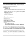
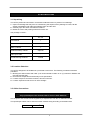
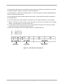
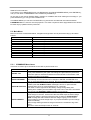
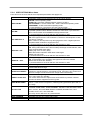
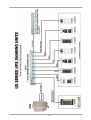
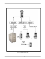
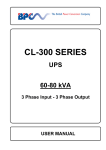
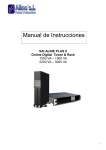
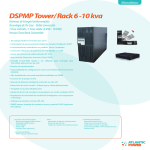
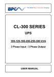
HP-100 SERIES UNINTERRUPTIBLE POWER SUPPLIES ( 1 Phase Input & Output ) HP-115 ( NS151A ) USER MANUAL CONTENTS I. SAFETY................................................................................................................................... 1 II. INTRODUCTION ..................................................................................................................... 2 2.1 System Description .......................................................................................................... 2 2.2 Technical Specifications................................................................................................... 4 III. INSTALLATION....................................................................................................................... 6 3.1 Unpacking ........................................................................................................................ 6 3.2 Location Selection............................................................................................................ 6 3.3 Cable Connections .......................................................................................................... 6 3.4 Start-Up ............................................................................................................................ 8 IV. OPERATING PROCEDURE ................................................................................................... 9 4.1 Turn On procedure........................................................................................................... 9 4.2 Turn Off procedure........................................................................................................... 9 4.3 When Utility Power Is Interrupted .................................................................................... 9 4.4 Automatic battery test system (Optional) ........................................................................ 9 V. FRONT PANEL ....................................................................................................................... 10 5.1 Introduction ..................................................................................................................... 10 5.2 Front Panel Menu Descriptions........................................................................................ 10 5.3 Main Menu ....................................................................................................................... 11 5.3.1 COMMAND Menu items ........................................................................................ 11 5.3.2 MEASURES Menu items ....................................................................................... 12 5.3.3 ALARMS Menu items ............................................................................................ 12 5.3.4 USER OPTIONS Menu items ................................................................................ 13 5.3.5 TIME Menu items .................................................................................................. 14 5.3.6 CALIBRATION Menu items ................................................................................... 14 5.3.7 ADJUST MODE submenu ..................................................................................... 14 5.3.8 INFORMATION Menu items .................................................................................. 14 5.4 Fault messages and quick troubleshooting...................................................................... 15 5.5 STATUS Messages ......................................................................................................... 16 VI. OPTIONAL EQUIPMENT........................................................................................................ 17 6.1 Software Options.............................................................................................................. 17 6.1.1 T-MON Software ................................................................................................... 17 6.2 SNMP Module .................................................................................................................. 18 6.3 UPS DB-9 (female) port definition.................................................................................... 18 6.4 Remote monitoring panel (RMP) ..................................................................................... 19 6.5 UPS Port Sharer (Multiple server shut down unit) ........................................................... 19 6.6 RSC24 RS232 / RS485 Interface .................................................................................... 19 VII. CUSTOMER SERVICE ........................................................................................................... 22 7.1 Maintenance..................................................................................................................... 22 7.2 Troubleshooting ............................................................................................................... 22 7.3 Storage............................................................................................................................. 22 VIII. LIMITED WARRANTY .......................................................................................................... 23 I. SAFETY This manual contains important instructions for HP-100 series UPS that should be followed during installation and maintenance. IMPORTANT NOTICES 1. Read instructions carefully before operating the UPS 2. All warnings in the manual should be adhered to. 3. All operating instructions should be followed. 4. The unit should be supplied by a grounded outlet. Do not operate the unit without ground source. 5. Power cord of the UPS should be routed carefully so that they are not to be walked on. 6. Please save this manual. 7. Please save or recycle the packaging materials. WARNING! • • • Do not insert any object into ventilation holes or other openings. To reduce the risk of fire or electric shock, install in temperature and humidity controlled indoor area free of conductive contaminants. To reduce the risk of fire, replace fuses with the same type and rating when necessary. CAUTION! • Only qualified personnel should install or service UPS/batteries. • Risk of electric shock, do not remove cover. No user serviceable parts inside, refer servicing to qualified service personnel. • The output may be energized when the unit is not connected to a mains supply. • Risk of electric shock hazardous live parts inside this unit are energized from the battery supply even when the input AC power is connected. • To reduce the risk of electric shock, disconnect the UPS from the mains supply before installing a computer interface signal cable. Reconnect the power cord only after signalling interconnections have been made. ABOUT THE BATTERY • • A battery can present a risk of electric shock or burn from high short circuit currents. The following precaution should be observed when working on batteries : * Remove watches, rings or other metal objects. * Use tools with insulated handles. The batteries in this UPS are recyclable. Batteries must be disposed of according to local environmental laws. The batteries contain lead and pose a hazard to the environment and human health if not disposed of properly. • Do not dispose of batteries in a fire. The batteries will explode. Do not open or mutilate the batteries. They contain an electrolyte which is toxic and harmful to the skin and eyes. If electrolyte comes into contact with the skin the affected area should be washed immediately. • The internal energy source (the battery) cannot be de-energized by the user. 1 II. INTRODUCTION Thank you for selecting this uninterruptible power supply (UPS). To choose the HP-100 series as your equipment protector was a wise investment. It includes many features to protect your critical equipments. The HP-100 series UPS system is connected between mains and critical loads, such as computer systems, telecommunication systems, computerized instruments etc. The advantages of using UPS: • Increased power quality: The UPS has its own internal voltage and frequency regulator circuits which ensure that its output is maintained within close tolerances independent of voltage and frequency variations on the mains power lines. • Increased noise rejection: By rectifying the input ac power to dc power, and then converting it back to ac, any electrical noise that may present on the input mains supply line is effectively isolated from the UPS output, therefore the critical load sees only clean power. • Power blackout protection: If the mains power fails, the UPS continues to power the critical load from its battery source, leaving the load immune from power disturbances. 2.1 System Description Features : • On-line technology with pure sine wave output. • PWM and IGBT technology. • Microprocessor controlled main controller board. • Static (STS) and maintenance by-pass. • LCD (Liquid Crystal Display) display. • Alarm history ( Memory for max. 64 alarms. ) • Automatic battery testing (optional). • High quality maintenance-free lead-acid type batteries. • High nonlinear load capacity, special for computers. • Accessories : o Optional UPS monitoring software ( T-MON, RUPS , RUPSII , UPSILON 2000 ) SNMP devices, compatible to any operating system. o Remote Monitoring Panel (RMP) available : You can observe the UPS status and parameters without using a computer at a remote location up to 200 meters away ( via RS485 interface). o UPS Port Sharer available HP-100 Series Uninterruptible Power Supplies (UPS) are advanced true On-Line Sine wave devices with static transfer switch which provide reliable, regulated, transient-free AC power to sensitive equipment. Since the UPS is a true On-Line system, conditioned power is provided continuously to the connected equipments. Unlike standby power systems, the UPS is constantly regulating and filtering the output power. When incoming power is interrupted, the UPS protects the computers instantaneously without any transfer time. The HP-100 Series has high non-linear load capability (i.e. Crest Ratio 3:1) and this is suitable for powering special loads such as switching power supplies or highly capacitive inputs like computers. The system's static transfer switch (STS) provides by-pass power as its standby source. During an overload condition, the S.T.S will switch the customer's load over to the bypass line with no interruption. The S.T.S will transfer back to the inverter automatically when the overload condition has been cleared. If the inverter fails internally, the unit switches to bypass within a few milliseconds. 2 Mechanical Transfer Switch Static Transfer Switch Static By-Pass AC Input AC Output Inverter Rectifier Battery Charger Battery Group Figure 2.1 UPS Block Diagram Rectifier : The first stage of the UPS. It supplies the DC bus voltage, which is necessary for operating the inverter by rectifying line voltage. Inverter : It is made by utilizing the latest technology of power transistor (IGBT) and pulse width modulation (PWM). Inverter converts dc bus voltage into an alternative voltage like line voltage. And provides this voltage and frequency being fixed. Static Transfer Switch (static by-pass) : Static transfer switch is an electronically controlled switching circuit checked by main controller board. In case of inverter overload or any other faults, STS transfers the critical load to the mains without any interruption. Mechanical Transfer Switch (Opsiyonel) : The mechanical transfer switch consists of a manually operated switch. When the UPS is switched off due to failure or maintenance, it feeds critical loads from mains. Battery Group : It keeps dc voltage, which is necessary for the inverter, as a reservoir dc power supply in case of mains failure. Battery Charger : It produces a well regulated dc voltage suitable for charging the UPS batteries. 3 2.2 Technical Specifications HP-115 Power 15 kVA Power Factor 0,7 Automatic Battery Test Optional Alarm Relays RS 232 INPUT Input Voltage 220 or 230 VAC 1Ph + N Input Voltage Tolerance + 15%, -20% 220 or 230 VAC ±10% By-pass Voltage Input Current 85 A 50 Hz. ±5% Input Frequency RFI Level EN50091 OUTPUT Nominal Output Power 10500W Output Voltage 220 or 230 VAC ±1% Output Voltage Tolerance Output Frequency 50 Hz. Line Synchronized ± 1% Output Frequency Tolerance Free Running ± 0.2% Efficiency (100% Load) 85-87 % Crest Factor 3:1 100% - 125% Load 2.5 min. 125% - 150% Load 10 sec. >150% instant by-pass. < 3% Overload capacity Total Harmonic Distortion (THD) BATTERY Batteries 20x12V Floating Charge Voltage 270 Vdc End of Discharge Voltage 200 Vdc Autonomy Time (100%Load ) 10 min. Charging Current 2.5 A ENVIRONMENT o Operating Temperature 0 - 40 C Acoustic Noise <55dBA Dimension (HxWxD mm) 725 x 300 x 790 Relative Humidity (max.) 90% 4 W D H Figure 2.2 Front View RS232 and Alarm Contact Outputs PK1 On / Off Switch AC Output Connections F1 - AC Input Fuse F2 – Batt. (+) Fuse F3 – Batt. (-) Fuse Rear View 5 III. INSTALLATION 3.1 Unpacking The UPS is packed and enclosed in a structural cardboard carton to protect it from damage. 1. Inspect for damage that may have occurred during the shipment If any damage is noted, call the shipper immediately and retain the shipping carton and the UPS. 2. Carefully open the carton and take the UPS out. 3. Retain the carton and packing material for future use. Unit package contents : HP-115 User Manual Guarantee Certificate Battery Cabinet Additional battery cabinet Optional 220V Input cable - UPS Monitoring Software T-MON 3.2 Location Selection The UPS is designed to be installed in a protected environment. The following conditions should be prohibited. 1. Blocking the airflow intake and outlet. (It is recommended to retain 10 cm (4”) minimum. Between the rear side and the wall.) 2. Environment temperature and humidity out of specification. 3. Location subject to excessive moisture, dust and corrosion. 4. Location exposed to heat source or direct sunlight. 3.3 Cable Connections CAUTION! Only qualified personnel should install or service UPS / batteries. The ac input to the UPS should be supplied by a separate line from the ac distribution board. The input/output cables can be sized to suit the modules rating according to the table below. 15 kVA 3 x 16 mm 2 6 The safety earth cable must be connected to the earth bus bar and bonded to each cabinet in the system. All cabinets should be earthed in accordance with local regulations. The UPS itself has no effect on the earthing quality i.e. it doesn’t change the unwanted voltage difference between the earth and neutral lines. Once the equipment has been finally positioned and secured, connect the power cables as described in the following section. It is recommended that the UPS should be connected to the line voltage protected by a circuit breaker. 1. Before connecting AC and DC power to the UPS make sure that the On-Off Switch PK1 and Main Switch on the rear panel are in the "0" position "OFF". 2. Connect the AC and/or DC input power to the UPS according to the label on the rear panel. Perform the load connections according to the same label too.. 3. Check if the connections are correct. (battery polarity, ac voltage ratings etc.) F1 : F2 : F3 : AC Input Fuse Battery (+) Fuse Battery (-) fuse AC Output Connections AC Input Connections Battery Cabinet Connections Figure 3.2 UPS Electrical Connections 7 3.4 Start-Up 1. Turn on the Main Switch on the rear panel. (In this case, there is line voltage at the output and battery charger board is active) 2. Turn the On-Off Switch PK1 on the rear panel to "1" position. In a few seconds the cooling fan will start to operate, then the red LED "by-pass" indicator will be off and the green LED indicator "inverter" will turn on and the UPS will start to give the inverter power to the output. 3. Disconnect the input power. The "LINE FAILURE" indicator will be on and audible alarm will sound intermittently. Now the output receptacles are supplied from the battery source. 4. Connect the power again and see that "LINE FAILURE" alarm is off. 5. Now your UPS is ready to operate. Plug in the critical loads to the output receptacles of the unit. NOTE If any condition is different from the above situation, call our local service representative for assistance. CAUTION ! After initial start-up, keep power continuously to the unit for at least 12 hours to ensure that the batteries are fully charged. During battery charging, the inverter can be shut down by turning the On-Off Switch PK1 to " Off - 0 " position. In this case the main switch should be kept in " On-1 " position and it must be kept in mind that there is line voltage at the output. 8 IV. OPERATING PROCEDURE 4.1 Turn On procedure 1. Turn on the Main Switch on the rear panel to "1" position. (There is line voltage at the output.) 2. Turn on the On-Off Switch PK1 on the rear panel to the "1" position. Turn on the power switches on your critical load after the "Inverter" indicator (green light) is turned on. (There is inverter voltage at the output.) 4.2 Turn Off procedure 1. Turn off all the power switches on your critical equipments that are connected to the UPS. 2. Turn off the On-Off switch PK1 and the Main Switch to "0" position. CAUTION A- For daily TURN ON / TURN OFF operation, it is recommended to keep the Main switch at "1" position to ensure proper battery operation. B- If the Main switch is in "1" position the line power will be supplied to output receptacles directly. DO NOT insert objects other than equipment power cords into outlets. 4.3 When Utility Power Is Interrupted In case the utility power is interrupted, the UPS converts the built-in battery source to output terminals immediately to protect your critical loads from loss of data or damage. Battery back-up time is more than 10 minutes for full load and can be extended by removing non-critical loads. After an utility power blackout, the audible alarm and "LINE FAILURE " indicator on LCD panel will start operating.1 minute after the power is interrupted, and you will see the message "BAT.USED :001min"on the LCD panel. This will show you for how long the batteries were used since the power was interrupted. When the "Battery Low" alarm appears, you have to shut down all your loads immediately, and turn the main switch PK1 to position "0". 4.4 Automatic battery test system (Optional) : There are some conditions to make this test ( e. g availability of by-pass supply, line synchronization,. a min. time requirement since the last line failure etc.). The first test is performed automatically, 8 hours later following the first turning on of the UPS. There is a 65 hours interval between two successive tests an each test lasts about 36 seconds. During the battery test operation, the inverter power will be supplied from batteries. At the end of this test,if the battery voltage is below a predetermined value, " BATTERY FAILURE / BATTERY LOW Fault messages appear on the LCD panel and the UPS starts operating in By-Pass mode. In this case you have to call your service. If the batteries are in normal conditions the system will start operating in normal mode after 36 sec. This test protects your operation against unexpected battery failures, and indicates you if there are any damaged batteries. It also discharges the batteries periodically, which is a good thing for extending battery life. 9 V. FRONT PANEL WARNING! The messages in this section are applicable for equipments having software version Y12C. If the version changes, the messages and functions will change as well. 5.1 Introduction The front panel of UPS, consisting of a 2 lines alphanumeric display, 2 status lamps, plus 3 function keys, allows the complete monitoring of the UPS status. The mimic flow diagram helps to comprehend the operating status of the UPS. By using the function keys operator can move on menus and change some parameters. ENTER Figure 5-1 By-Pass : If lamp is lit static bypass is active and load is connected to mains voltage Inverter : If lamp is lit inverter supplies the load There are 3 function keys on front panel these are ENTER, DOWN and (↔ ↔). DOWN keys help moving on menus, (↔ ↔) key selects options, ENTER key means the selected option or menu is valid. NOTE : During parameter settings, “+” sign will change into “—“ sign if “↔ ↔” button is pressed for 3 seconds and the parameter values will start decreasing. 5.2 Front Panel Menu Descriptions By using menu buttons on the front panel you can move on main menu functions. You can enter the submenu of the item seen on the LCD panel (MEASURES, ALARMS, INFORMATION) and navigate within it by using again and ↵ (Enter) buttons. MEASURES LOAD ..: % OUTPUT.:000 V IPV:000 V IPV:000 V IPV:000 V BATTERY: V ...... etc (output load percentage ) (output voltage ) (output frequency ) (input voltages ) (bypass voltages ) (battery voltage and current ) 10 SAMPLE menu selection : If you want to go to MEASURES menu use DOWN keys and find MEASURES MENU, press ENTER key, now you can move on MEASURES menu subitems by DOWN keys. At the end of sub menus ENTER (EXIT) message is available and while reading this message, if you press ENTER key you can go back to MAIN menu. In ALARMS MENU you can see LOG HISTORY, log events are recorded with event time and date. PASSWORD Menu is used for service purposes. This menu requires a three digit password and should be used only by qualified service personnel.. 5.3 Main Menu Main menu items are described below, navigation through them can be performed using up and down buttons. Main menu items STATUS COMMAND MENU MEASURES MENU ALARMS MENU USER OPTIONS TIME MENU CALIBRATION MENU ADJUST MENU INFORMATION MENU Go to STATUS MENU 5.3.1 Function The status message which shows the UPS status → Enter “go to Command submenu” → Enter “go to Measures submenu” → Enter “go to Alarms submenu” → Enter “go to User Option submenu” → Enter “go to Time submenu” → Enter “go to Calibration submenu” → Enter “go to Adjust submenu” → Enter “go to Information submenu” COMMAND Menu items This menu is used to give commands to the UPS or perform tests on it. Submenu item SOUND : ON ENTER <BYPASS> ENTER B.TEST>000 ENTER <BOOST> Function Used for turning on/off alert sound. If you press ENTER key the option will change,one press ON,one press OFF. If the OFF option is selected sound alert is turned off but if a new alarm, UPS changes the option to ON state. If you press ENTER for 3 seconds, the load is transferred to BYPASS automatically and the submenu item changes to ENTER <INVERTER> this time. If you press ENTER for 3 seconds, the load is transferred back to Inverter. If you press enter for 3 seconds battery test starts and lasts for 15 seconds. If battery test fails A6 BATT FAULT message is shown on panel and this message stays until you press ENTER key for 3 seconds. The value on at the right shows the battery voltage during battey test. Starting time of battery test recorded to log event menu if the test is successful you can see only BATTERY TEST message on log records.. If you press ENTER key for 3 seconds boost charge starts. The given time for boost charge is 10 hours. At the end of this time UPS stops the boost charge. If the boost charge is active this submenu item changes to STOP BOOST> 005H message the 005H shows that boost charge is going on for 5 hours. If the number is 10 boost charge stops. If you press ENTER key boost charge stops immediately. Boost charge starting and boost charge end times are recorded to log event menu. If boost is active UPS beeps each 15 seconds 11 Submenu item SIMULATION:OFF ENTER>FAULT RST <ENTER> EXIT Function The purpose of this submenu to check dry contact connections. Normally to check line failure contact you must turn off mains power. This is not necessary with this utility. 3 options are available. SIMULATION OFF simulation mode is off SIM:LINE FAILURE if you press ENTER key for 3 seconds the line failure lamp on interface board is turned on. SIM:LIN.F+BT.LOW if you press enter key for 3 seconds the line failure and battery low lamps on interface are turned on. SIM:BYPASS if you press ENTER key for 3 seconds the bypass (aux) lamp on interface board is turned on. So you can check dry contact connections Faults reset selection. → Enter (↵ ↵ ) exit from submenu 5.3.2 MEASURES Menu items All the measurements of the UPS can be monitored via this menu, navigation through the items is performed using up and down buttons. Submenu item LOAD ..: % OP.CURR: A OUTPUT.:000 V IPV:000 V BATTERY: V BYPASS.: V FR: HZ TEMP.:000 C NORM BAT.TIME:--- min <ENTER> EXIT Function Output load percentage Output current Output voltage 3 Phase input voltages Battery voltage By-pass voltage Input frequency – Output frequency UPS Internal temperature Battery time → Enter (↵ ↵ ) exit from submenu 5.3.3 ALARMS Menu items The last 28 events can be monitored in this menu. Submenu item UPS STATUS 000> LOG EVENT PAR.ERR: <ENTER> EXIT Function Alarm status at that instant. Monitoring past alarms: First 3 digit number indicates the event number, 000 event is the last one. Date is in ddmmyy and time is in hh:mm format. On the second line, the alarm events on the first line are listed. Using ↔ button 128 events can be viewed. Parallel controller board error (If parallel hardware exists) If this value is 0 then the parallel is OK → Enter (↵ ↵ ) exit from submenu 12 5.3.4 USER OPTIONS Menu items From this menu the user selects some important parameters and apply them. Submenu item MOD:ONLINE UPS NR.: BYP.PROTECT.:0 RESTART: OFF REMOTE....:OFF LANG.:ENGLISH BOOST TIME: HR BOOST:AUTOMATIC DIRECT START:OFF XFER MODE:CURR. RL5:DC LOW AUX1:COMMON AUX2:COMMON <ENTER> EXIT Function 4 Operating modes can be selected using up and down buttons. ONLINE: normal operating mode. PARALLEL: Symmetric parallel operation mode of 2 UPS’s. HOT STANDBY: 1 UPS is master and 1 UPS is redundant operating mode. REDUNDANT: 2 UPS’s redundant operating mode. → Press ENTER for 3 seconds to save the selected mode. By using PLUS and MINUS keys you can change number 0 to 3. In parallel operation select different numbers for each UPS. If you select the same number DUBL UPS NUMBER message tells the fault. → press ENTER for 3 seconds and then the selection is valid By using ↔ key you can change on and off options. ON: if the bypass source is out of tolerance, UPS turns off load power in case of a fault or overload. OFF : UPS turn off load power only during bypass moves. If bypass period is completed UPS continues to supply the load. → press ENTER for 3 seconds and then the selection is valid By using ↔ key you can change on and off options. ON : during mains failure at the and of battery discharge UPS shutdowns, after mains restored UPS starts again. (battery trip out is on every time) OFF: after mains restoration UPS doesn’t start again. (battery trip out is off) → press ENTER for 3 seconds and then the selection is valid By using ↔ key you can change enable and disable options. ON : remote battery test, shutdown and bypass functions are enabled OFF: these functions are disabled → press ENTER for 3 seconds and then the selection is valid Turkish – English is selected. Quick charge period of 1-15 hours is configured. Boost is disabled if 0 is entered while boost charge. Manual – automatic modes are selected using ↔ key. Normal charge mode operates in manual selection. In automatic mode, if the line is off, at each time input line voltage is restored the boost charge starts automatically. ON: UPS at the beginning starts automatically. OFF: The inverter is in standby. The inverter starts and the output forms when ENTER is pressed. Until this moment the load is supplied from the by-pass. CURRENT : Switches into bypass without delay when the current is zero DELAY : If the UPS is not synchron, switching into bypass takes place with 15 ms. Delay. Alarms : COMMON,RL4, BATT. LOW, OUTPUT HĐGH, OVERLOAD, LĐNE FAILURE, OVER TEMP., OVER CURRENT, OUTPUT LOW, BATTERY HĐGH, BATT. FAULT, BY-PASS BAD, BOOST CHARGE, MANUEL BYP, ROT. PHASE, OUTP. OFF, UPS FAILURE. RL5 relay can be defined for any desired alarm. Selectable function dry contact relay output Selectable function dry contact relay output → Enter (↵ ↵ ) exit from submenu 13 5.3.5 TIME Menu items You can see date and time of RTC (real time clock) on UPS. And you can adjust date and time. Submenu item TIME: 00:00 DATE: XX-XX-20XX SET HOURS: SET MINS : SET DAY : SET MONTH: SET YEAR : 2009 ENTER <UPDATE> <ENTER> EXIT Function time date (+) and (-) adjust hours (0-23) (+) and (-) adjust minutes (0-59) (+) and (-) adjust day (1-31) (+) and (-) adjust month(1-12) (+) and (-) adjust year (2000-2099) → Enter update new date and time → Enter (↵ ↵ ) exit from submenu 5.3.6 CALIBRATION Menu items This menu is used to adjust time and date of the UPS. Submenu item (Password required ) ENTER EXIT Function System adjustments. → Enter (↵ ↵ ) exit from submenu 5.3.7 ADJUST MODE submenu This menu is used to adjust time and date of the UPS. Submenu item (Password required ) ENTER EXIT Function System adjustments. → Enter (↵ ↵ ) exit from submenu 5.3.8 INFORMATION Menu items This menu gives information about the UPS Submenu item COMM:OK SYNC:OK VA.POWER:15000 VER:Y12C <ENTER> EXIT Function If the UPS is operating syncron to mains SYNC:OK,if not syncron SYNC:-If communication is active COMM:OK,if not active COMM:-The maximum power rating of the UPS Shows the UPS software version → Enter (↵ ↵ ) exit from submenu 14 5.4 Fault messages and quick troubleshooting All alarms contained in Y12C version are listed in the following table. ALARM A1 BYP FAILURE A2 INV FAILURE A3 3 OVERTEMP A4 OUT FAILURE A5 BATT AUT END A6 CHARGER FAULT A7 BATTERY LOW A8 OUTPUT HIGH A9 OVERLOAD A10 LINE FAILURE A11 HIGH TEMPER A12 OVERCURRENT A13 OUTPUT LOW A14 BATTERY HIGH A16 BYP INP.BAD A19 REPLACE BATT A20 BOOST CHARGE A21 ROTATE PHASE A22 OUTPUT OFF POSSIBLE CAUSE Bypass system failure. Bypass elements may be broken. Inverter digital start system is failed. Call the service. Overtemperature in UPS repeated 3 times in 30 min. 1) Check for UPS air inlets and outlets for any blocking by dust etc. 2) Fan failure 3) Bad UPS location 4) Check for Overload UPS output voltage is out of tolerance at 3 times in 30 min. Call the service. Batteries are completely discharge wait for restoration of electric power input.This message occurs only at line failure Rectifier could not produce DC bus voltage. Battery voltage is low. 1) UPS operation for a long time when line out 2) Charger system failure Inverter output voltage is over than max. tolerated value. Inverter is stopped 1) Inverter failure UPS loaded over than max. %100 load level. Line failure. 1) Maybe line out 2) Check 3 input phases. 3) Check UPS input fuses. Over temperature. (inverter or rectifier section) 1) Overload for inverter 2) Over temperature 3) Fan failure or dirty air inlets 4) Bad UPS settling. There is not enough ventilation area. Inverter output system failure 1) Internal overcurrent 2) Short circuit. 3) UPS failure. Call the service. Inverter output voltage is below the min tolerated value. Inverter is stopped. Battery voltage is over than max. tolerated value. If the mains is off the tolerance when switching into bypass. The UPS turns off the output voltage and waits until the inverter starts again to prevent the load. During transfer to bypass,Voltage or frequency value of bypass source is incorrect and the UPS turns off the load power. During normal (inverter) operation some times you can see this message. During bypass if the bypass protection option is on, and if the bypass source is out of tolerance UPS turns off the static bypass for load protection. Battery test aborted. And batteries are not OKAY UPS gives beep sound within 15 sec You can clear this message by pressing 3 seconds to ENTER key 1) Rectifier fault 2) Damaged battery cells 3) POOR battery connections Boost charge is active for 10 hours. At the end of this time UPS stops the boost charge. UPS gives beep sound every 15 sec UPS input phases sequence is not correct 1) Turn off the UPS and rotate phase sequence 2) Turn on UPS again Output OFF alarm - Output switch may be off. - A fault may be in the output. Check the output components. 15 ALARM A23 MODE FAILURE A24 P.FAILURE 10 A25 PAR. PSP FAIL A26 4 CABLE FAIL A27 P.FAILURE 13 A28 PLUG IN DIG. A31 DUBL UPS NR. A40 CANT FIND PR A41 P.BAL.FAIL. A42 BATTERY TEST A43 P.SYNC.FAIL. A48 STATIC BYPS. A50 EMERGE.STOP A51 MAINT.SW.ON A52 MANUA.BYPASS A53 CHECK +6V A54 CHECK DC 1 A55 P.DLY.FAIL A59 REF.FAILURE POWER ON PAR FAILURE 4 PAR FAILURE 5 PAR FAILURE 6 PAR FAILURE 7 PAR FAILURE 8 POSSIBLE CAUSE In parallel operation the slave device tries to operate as the same mode as the master device, If the modes are different this message will appear. Change the mode of the slave UPS from USER OPTION MENU. Press ENTER button for 3 seconds after mode selection, then restart the UPS. RS485 failure Power supply error in parallel controller board. Master-Slave digital cable connection error. Parallel controller board failure, online UPS found in parallel system. Digital connection cable plug in failure Parallel UPS numbers are same change one of them Parallel mode is selected but main controller could not find parallel control board. Select ONLINE mode from SETTING MENU. Turn off the ups and turn on again. In parallel operation current sharing is not okay Performing battery test In parallel system SLAVE UPS is not synchronized to MASTER UPS 1) Wait for 10 seconds the UPS will be restart Load is transferred statically to bypass Emergency stop button is pressed. Maintenance bypass switch is open. (optional) Yük elle bypass girişine transfer edildi Check +6V on them main controller board. Battery voltage is below the lower limit. Parallel delay fault 2.5 V ADC reference voltage on MPB211 main controller board exceeds predefined tolerances. Cihazın ilk açıldığını gösteren mesajdır. Paralelleme Hatası Paralelleme Hatası Paralelleme Hatası Paralelleme Hatası Paralelleme Hatası 5.5 STATUS Messages This message group simply shows the UPS STATUS at the upper line of LCD PANEL. MESSAGE BTT.TEST DISABLE BYPASS DISABLED MANUAL BYP.SW.ON ENTER <BYPASS> RECTIF.START! STATUS NORMAL INVERTER START MAINT.SW ON! EMERGEN.STOP! MANUAL BYPASS! <ENTER> START! WAIT SHUTDOWN UPS SHUTDOWN WAIT RESTART SHUTDOWN&RESTART POSSIBLE CAUSE If battery test cannot be perform from any reason this message will be showed. If load cannot be transfer to bypass from any reason this message will be showed. Maintenance Bypass Switch On If the user press Enter button load will transferred to bypass. UPS started the rectifier UPS is operating. UPS started the inverter. Maintenance bypass switch is on External emergency stop signal is applied to UPS. Load is transferred to bypass input manually. Press ENTER to start the UPS. Shutdown command is performed from operating system and UPS is waiting for a certain delay for shutdown. UPS is in shutdown status UPS is shutdown but it is waiting for a certain delay for restart Shutdown command received from RS232 interface. Currently UPS is in slip mode. After given time delay it will be restart again. 16 VI. OPTIONAL EQUIPMENT 6.1 Software Options The UPS can send digital data (optional) to the computer thought the RS232 port. No additional card is needed. It also has two alarm relays: Line failure and battery low. Computer systems require time to perform an orderly shutdown, without corrupting or losing data In an extended power failure, a computer system protected by a UPS eventually will lose power when the battery is exhausted. Using a UPS monitoring (T-MON, RUPS, RUPSII, UPSILON 2000) software the UPS and the computer system communicate so that the computer system is warned of impending UPS shutdown. Software (T-MON, RUPS , RUPSII , UPSILON 2000 ) and SNMP devices, is available for most operating systems and is supplied with a signaling cable that connects to the UPS. RUPS software supports alarm relay option. (Line Failure & Battery Low) Cable code:M2501 / CC04 T-MON, RUPSII & UPSILON 2000 software support RS232 option. Cable code:M2502 / CC05 6.1.1 T-MON Software Using this software all the monitoring and control functions of the LCD panel of the UPS can be performed using your PC or Server. It is also possible to monitor a remote Ups with TCP/IP protocol and to shutdown your server and users with T-MON server Connector Software. Operating systems : MS Windows 95-98-2000-XP, NT Server, UNIX Client. 17 6.2 SNMP Module Using the SNMP module, your UPS is seen as a network device in your WAN or LAN applications, and with this way it can be monitored more than one UPS’s connected to your network through SNMPVIEW Software supplied with the module or it is possible to monitor the UPS through an Internet Browser. It is possible to shutdown the servers or users with Client mate Software that communicates with SNMP module. 6.3 UPS DB-9 (female) port definition : Pin assignments Line Failure Relay Common Line Failure Relay NO Battery Low Relay Common Battery Low Relay NO RS232 Signal Gnd RS232 Receive RS232 Transmit Pin number 4 2 4 5 7 6 9 1, 3, 8 Not Connected 18 6.4 Remote monitoring panel (RMP) You can see UPS status and parameters without using a computer up to 200 meters ( via RS485 interface). And you can connect more than one remote panel in cascade for monitoring your UPS system from several different locations at the same time. 6.5 UPS Port Sharer (Multiple server shut down unit) Using one of this units, you can automatic shut down of 4 / 8 servers or PC (where without LAN) connected to the same UPS by RUPS software. Please look at the following connection diagram. US-8 US-4 6.6 RSC24 RS232 / RS485 Interface This interface should be used if the distance between the UPS and its remote monitoring panel exceeds 20 meters. 19 20 ( T-MON ) COM1 Connection Diagram Of The RMP 21 VII. CUSTOMER SERVICE WARNING! There are no customer serviceable components inside. DO NOT open the cover or attempt to service the unit. High voltage may remain when the unit is shut down. Unauthorized service will void the warranty and could cause serious injury. 7.1 Maintenance The unit is designed for easy maintenance. Very little customer maintenance is required. The following will help to ensure trouble -free operation for several years: 1. Vacuum the dust from the ventilation intake on the front panel. 2. Wipe the cover with a dump cloth. 3. Periodically unplug the power cord of the UPS from the wall outlet to test the batteries automatic battery testing option not available.) condition (If CAUTION! It is recommended to test the battery discharging capability only after the software in use has been saved and all files have been closed. 7.2 Troubleshooting Due to the unique design, the unit can be serviced only by authorized people. In case of a persistent failure or problem properly turn off the unit first. Then review the following check list. Be prepared to answer the questions before calling the service. 1. Did you follow the operation procedure? Did it happen on installation? 2. Is the on-off switch PK1 on the rear panel turned to position "1"? 3. Is the utility power of the wall outlet correct? 4. Did a power failure occur just after or before the malfunction noted on the UPS? 5. What is the indicators status? (see LCD alarms and FAULT codes) 6. Were any changes made recently to unit or the critical equipment connected to the unit? 7. Did an overload condition occur? Remove load from the unit and restart it. 7.3 Storage 1.Check the batteries charge with the manual battery test before storage. 2.Connection’s uninstall operation will be done by the authorized service. 3.During the storage period the batteries should be charged once, per six months. 4.Keep the equipment and the batteries in a dry, cool place. Best storage temperature for the UPS : Between 0°C and 40°C max. Best storage temperature for the batteries : Between 10°C and 35°C max. 22 VIII. LIMITED WARRANTY The UPS is warranted against all defects in workmanship and materials under normal use for a period of one ( ) year from the date of shipment to the original user. The conditions of this warranty and the extent of responsibility of ………………………………………………………………………………………………………………………….. corporation under this warranty are as follows. 1. The warranty does not apply if the product has been subjected to physical abuse, improper installation, unauthorized service or modification. 2. The sole responsibility of ………………………………………………………………………………………………………………………….. corporation under this warranty shall be limited to the repair or replacement of the product, at the sole discretion of ………………………………………………………………………………………………………………………….. corporation. 3. If it becomes necessary to send a defecting unit to ………………………………………………………………………………………………………………………….. corporation, the product should be shipped in its original carton or in suitable equivalent, and with shipping charges prepaid. ………………………………………………………………………………………………………………………….. corporation will not assume any responsibility for any loss damage incurred in shipping. 23 AGKK8480 06/2009