1
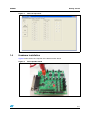
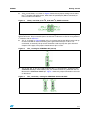
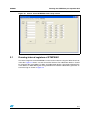
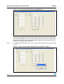
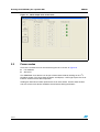
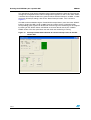
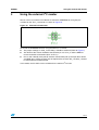
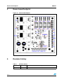
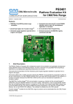
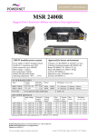
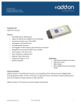
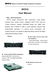
UM0401
User manual
User manual for eight bit port expander
STMPE801 demonstration board
Introduction
This document explains the functioning of the demo board for the port expander Chip
STMPE801 with a PC GUI for reading and writing to the eight GPIOs and controlling the I2C
interface.
The objective of this demonstration board is to display the capabilities of the 8-bit port
expander (STMPE801) developed by STMicroelectronics using a Windows-based software
application. The software application provides a user-friendly environment to test the port
expander and verify its functionality.
The board is controlled by the GUI through the parallel port in the PC. The power to the
board should come from an external 5 V constant DC power supply.
The PC based GUI acts as the I2C host and controls the STMPE801 slave on the board.
The eight GPIOs in the STMPE801 are accessible through headers and can be easily pulled
high or low using jumpers. The GPIOs can be configured as outputs by writing to the
appropriate registers using the GUI. All these interfaces are controlled by using I2C
communication between Host and Slave devices.
In addition, the hardware has a provision for controlling the STMPE801 through an external
I2C master.
June 2007
Rev 1
1/17
www.st.com
Contents
UM0401
Contents
1
2
Getting started . . . . . . . . . . . . . . . . . . . . . . . . . . . . . . . . . . . . . . . . . . . . . . 4
1.1
System requirements . . . . . . . . . . . . . . . . . . . . . . . . . . . . . . . . . . . . . . . . . 4
1.2
Package contents . . . . . . . . . . . . . . . . . . . . . . . . . . . . . . . . . . . . . . . . . . . . 4
1.3
Software installation . . . . . . . . . . . . . . . . . . . . . . . . . . . . . . . . . . . . . . . . . . 4
1.4
Hardware installation . . . . . . . . . . . . . . . . . . . . . . . . . . . . . . . . . . . . . . . . . 5
1.4.1
Power supply . . . . . . . . . . . . . . . . . . . . . . . . . . . . . . . . . . . . . . . . . . . . . . 6
1.4.2
Jumper settings . . . . . . . . . . . . . . . . . . . . . . . . . . . . . . . . . . . . . . . . . . . . 6
Running the STMPE801 port expander GUI . . . . . . . . . . . . . . . . . . . . . . 8
2.1
Running internal registers of STMPE801 . . . . . . . . . . . . . . . . . . . . . . . . . . 9
2.2
Programming GPIO . . . . . . . . . . . . . . . . . . . . . . . . . . . . . . . . . . . . . . . . . 11
2.3
Power modes . . . . . . . . . . . . . . . . . . . . . . . . . . . . . . . . . . . . . . . . . . . . . . 12
2.4
Configuring interrupts . . . . . . . . . . . . . . . . . . . . . . . . . . . . . . . . . . . . . . . . 13
3
Using the external I2C master . . . . . . . . . . . . . . . . . . . . . . . . . . . . . . . . 15
4
Demo board footprint . . . . . . . . . . . . . . . . . . . . . . . . . . . . . . . . . . . . . . . 16
5
Revision history . . . . . . . . . . . . . . . . . . . . . . . . . . . . . . . . . . . . . . . . . . . 16
2/17
UM0401
List of figures
List of figures
Figure 1.
Figure 2.
Figure 3.
Figure 4.
Figure 5.
Figure 6.
Figure 7.
Figure 8.
Figure 9.
Figure 10.
Figure 11.
Figure 12.
Figure 13.
Figure 14.
Figure 15.
Figure 16.
Figure 17.
Figure 18.
Figure 19.
GUI start up screen. . . . . . . . . . . . . . . . . . . . . . . . . . . . . . . . . . . . . . . . . . . . . . . . . . . . . . . . 5
Port expander board . . . . . . . . . . . . . . . . . . . . . . . . . . . . . . . . . . . . . . . . . . . . . . . . . . . . . . . 5
Voltage regulation from +5 V supply (VIN) . . . . . . . . . . . . . . . . . . . . . . . . . . . . . . . . . . . . . . 6
JP10_1 for Power supply . . . . . . . . . . . . . . . . . . . . . . . . . . . . . . . . . . . . . . . . . . . . . . . . . . . 6
JP55_2 and JP56_2 for I2C_CLK and I2C_SDATA selection. . . . . . . . . . . . . . . . . . . . . . . . 7
JP2_3 setting for STMPE801 INT pull-up . . . . . . . . . . . . . . . . . . . . . . . . . . . . . . . . . . . . . . . 7
JP3_3 and JP5_3 setting for STMPE801 SCLK and SDAT . . . . . . . . . . . . . . . . . . . . . . . . . 7
JP4_3 setting for STMPE801 I2C Slave address selection . . . . . . . . . . . . . . . . . . . . . . . . . 8
JP6_3 and JP7_3 setting for STMPE801 VCC and VIO connections . . . . . . . . . . . . . . . . . . 8
Screen shot of STMPE801 GUI startup screen . . . . . . . . . . . . . . . . . . . . . . . . . . . . . . . . . . 9
Screen shot of write/read tab in STMPE801 GUI . . . . . . . . . . . . . . . . . . . . . . . . . . . . . . . . 10
Error screen when the incorrect I2C slave address is chosen . . . . . . . . . . . . . . . . . . . . . . 10
GPIO Input state screen shot . . . . . . . . . . . . . . . . . . . . . . . . . . . . . . . . . . . . . . . . . . . . . . . 11
GPIO Output state screen shot. . . . . . . . . . . . . . . . . . . . . . . . . . . . . . . . . . . . . . . . . . . . . . 12
Entering in hibernate mode. . . . . . . . . . . . . . . . . . . . . . . . . . . . . . . . . . . . . . . . . . . . . . . . . 13
Interrupt setting tab screen shot . . . . . . . . . . . . . . . . . . . . . . . . . . . . . . . . . . . . . . . . . . . . . 13
Interrupt enabled with indication of current interrupt status in the ISR - screen shot . . . . . 14
External I2C connector . . . . . . . . . . . . . . . . . . . . . . . . . . . . . . . . . . . . . . . . . . . . . . . . . . . . 15
Demo board footprint . . . . . . . . . . . . . . . . . . . . . . . . . . . . . . . . . . . . . . . . . . . . . . . . . . . . . 16
3/17
Getting started
UM0401
1
Getting started
1.1
System requirements
In order to use the port expander demonstration board with the Windows operating system,
a recent version of Windows, such as Windows XP or Windows 2000 must be installed on
the PC. The user must have administrative rights to install the executable and launch it.
The version of the Windows OS installed on your PC may be determined by clicking on the
"System" icon in the Control Panel.
1.2
Package contents
The port expander demo board includes the following items:
●
●
●
1.3
Hardware content:
–
One demonstration board
–
One parallel port cable
Software content:
–
PC executable software (STMPE801_GUI) to be used along with demo board
–
A DLL file to support the executable (io.dll) to be installed in the same directory as
the executable file.
–
Source code (written in Borland Delphi)
Documentation:
–
User manual
–
Schematic of the hardware
Software installation
The GUI is a simple executable that can be run even from a USB flash drive. The only
requirement is that the user must have administrative rights on the system in order to open
the accompanying DLL file. The GUI can be started by double-clicking on the file
STMPE801_GUI.exe. When the exe file is opened, the GUI resembles Figure 1 below:
4/17
UM0401
Getting started
Figure 1.
1.4
GUI start up screen
Hardware installation
Figure 2 below shows the snapshot of the demonstration board.
Figure 2.
Port expander board
5/17
Getting started
1.4.1
UM0401
Power supply
The demo board should be powered from an external supply of 5 V, 1 A. (Connector X1 is
for +5 V and Connector X2 is GND). This supply is regulated to get the required VCC, VIO
and Vpull-up voltages by adjusting the Resistor divider components.
Figure 3 below shows the Voltage regulation circuit used. For example, a VCC of 1.8 V can
be achieved by fixing the R6_1 resistor to 680 ohms and calculating R7_1 using the formula:
Equation 1
1 + R 71
V OUT = V REF ⎛ --------------------⎞ + I ADJ R 71
⎝ R 61 ⎠
-
where, the VOUT we need is 1.8 V, VREF is 1.25 V and IADJ is 50 µA.
By default, the resistors are chosen to fix the voltages at VCC = 1.8 V, VIO = 3.3 V and
Vpull-up = 2.3 V in the demo board.
Figure 3.
1.4.2
Voltage regulation from +5 V supply (VIN)
Jumper settings
There are several jumpers on the board that should be properly set to ensure proper
functioning of the board.
●
JP10_1: as shown in Figure 4 below, the JP10_1 jumper should be set to power the
voltage Regulators with +5V from the X1 and X2 connectors. This is the main power
connection for all the components on the board.
Figure 4.
6/17
JP10_1 for Power supply
UM0401
Getting started
●
JP55_2 and JP56_2: as shown in Figure 5 below, these jumper settings are to select
the I2C CLOCK and DATA source, either from the parallel port (DB-25 connector) or
from an external I2C Master.
Figure 5.
JP55_2 and JP56_2 for I2C_CLK and I2C_SDATA selection
These jumpers should be connected if STMPE801 is to be controlled by the GUI through the
DB-25 connector. They can be left open if an external I2C Master is used. For using external
I2C Master, refer to Section 3.
●
JP2_3: as shown in Figure 6 below, JP2_3 is used to connect the INT pin to the pull-up
resistor and LED for easier monitoring of the generated interrupts. If this is not
connected, an external pull-up resistor should be used to pull up the open drain INT
output to VIO supply. The jumper should connect pins 1 and 2.
Figure 6.
●
JP2_3 setting for STMPE801 INT pull-up
JP3_3 and JP5_3: JP3_3 is used to connect the I2C_CLK from the I2C Master to the
STMPE801 SCLK pin. And similarly JP5_3 is used to connect I2C_DATA from the I2C
Master to the STMPE801 SDATA pin. Figure 7 shows the jumper connection to be used
on the board.
Figure 7.
JP3_3 and JP5_3 setting for STMPE801 SCLK and SDAT
7/17
Running the STMPE801 port expander GUI
●
JP4_3: JP4_3 is the jumper used to select the I2C slave address as either 0x82 or
0x88. There are pull-down and pull-up resistors for the respective selection and these
can be enabled by shorting the headers as shown in Figure 8.
Figure 8.
●
UM0401
JP4_3 setting for STMPE801 I2C Slave address selection
JP6_3 and JP7_3: These jumpers are provided to isolate the STMPE801 chip from the
rest of the board for troubleshooting. They can also be used as test points to measure
the respective supply operating current. To supply the chip with the VCC and VIO, these
jumpers should be shorted as shown in Figure 9.
Figure 9.
JP6_3 and JP7_3 setting for STMPE801 VCC and VIO connections
The board is ready to function after these jumper settings and the GPIOs can be accessed
through the different headers provided. Refer to Section 4 for the location of the various
jumpers on the board.
2
Running the STMPE801 port expander GUI
This port expander demo board consists of two main parts:
●
PC GUI
●
Demonstration board
The various jumpers on the board should be configured correctly before running the GUI.
In order to run the GUI, the demo board must first be connected to the PC with the DB-25
parallel port cable and the power supply of +5 V should be provided.
The user should login as administrator before running the GUI (STMPE801_DEMO.exe).
This file should be run from the same directory as the io.dll file.
When the GUI is successfully running, the startup screen resembles Figure 10. There are
four tab options for testing the various device functionalities as explained in the following
sections.
8/17
UM0401
Running the STMPE801 port expander GUI
Figure 10. Screen shot of STMPE801 GUI startup screen
2.1
Running internal registers of STMPE801
The internal registers of the STMPE801 can be read or written to using the "Write Read" tab
in the GUI. Figure 11 shows a screen shot of this function. The radio button device 1 should
be selected if the slave address is 0x82, and radio button device 2 should be selected if the
slave address is 0x88. Making the wrong selection on the device radio buttons generates an
error message as shown in Figure 12.
9/17
Running the STMPE801 port expander GUI
UM0401
Figure 11. Screen shot of write/read tab in STMPE801 GUI
The register contents can be read by writing the 8-bit hex address into the "Address" field
and the number of registers to be read in the "Length" field. Then click on the "Read" button.
The contents displayed are in Hex and 8-bits wide. The same procedure can be followed for
writing into the registers. The content to be written should be in bytes and only 8 bytes can
be written with a single "Write" button click.
Note:
The Length field should always be non-zero. A read or write with length zero causes the GUI
to close.
Figure 12. Error screen when the incorrect I2C slave address is chosen
10/17
UM0401
2.2
Running the STMPE801 port expander GUI
Programming GPIO
The eight GPIOs can be configured as input or output individually and independently of
each other. The status of the GPIOs can be read and are displayed on the "GPIO-functional"
tab of the GUI as shown in Figure 13.
As shown in Figure 14, GPIOs can be configured as outputs by selecting the corresponding
radio button for IN or OUT assignment and clicking the "GPIO Assignment" button. The
output state can be set to High or Low through the corresponding radio button and clicking
on the "Write" button. The resulting state of the GPIOs can be read and displayed by clicking
on the "Read" button.
Like the Read/Write to internal registers, the correct slave device should be chosen before
the GPIO is configured. If the wrong slave device is chosen, errors appear indicating there is
an error reading the GPMR or writing to GPDR registers depending on the function
performed.
Figure 13. GPIO Input state screen shot
11/17
Running the STMPE801 port expander GUI
UM0401
Figure 14. GPIO Output state screen shot
2.3
Power modes
There are 2 functions that can be tested using this tab as shown in Figure 15.
●
I2C shutdown
●
Soft reset
The STMPE801 slave devices can be put in Power down mode by clicking on the "I2C
Shutdown" button. This shuts down the device and displays a message to press the reset
button to resume normal device operation.
Clicking the "Soft Reset" button performs the reset of the device. Like the other function
tabs, the correct slave device should be chosen before clicking the buttons.
12/17
UM0401
Running the STMPE801 port expander GUI
Figure 15. Entering in hibernate mode
2.4
Configuring interrupts
The GUI provides a convenient way to configure the GPIO interrupts in STMPE801 and
monitor the change of state in the GPIOs that trigger interrupts, if so configured. Figure 16
shows a screen shot of the Interrupt tab before the interrupts are configured and running. It
allows configuring the interrupt polarity and the masking of each individual GPIO.
Figure 16. Interrupt setting tab screen shot
13/17
Running the STMPE801 port expander GUI
UM0401
The appropriate slave device should be chosen before enabling the interrupt. The Interrupt
settings are configured into the internal configuration registers as soon as the "SET" button
is clicked. The Interrupt window turns green to indicate that the interrupt is enabled. In order
to turn off all interrupt settings, click on the "Reset Interrupt" button . This is shown in
Figure 17.
The ISR can be monitored using the "Read GPIO Interrupt Status" panel. Once the "START"
button is clicked, the ISR is read at 100ms intervals and the results are displayed with
corresponding green squares for GPIOS with state change. This monitoring can be stopped
by clicking on the "STOP" button. All GPIOS are reset to default state by the "CLEAR
PANEL" button. The clear panel does not work when the monitoring is running
Figure 17. Interrupt enabled with indication of current interrupt status in the ISR screen shot
14/17
UM0401
3
Using the external I2C master
Using the external I2C master
We can also use an external I2C Master to control the STMPE801 by using the pins
available on the JP17_2 connector as shown in Figure 18.
Figure 18. External I2C connector
To control the STMPE801 devices using the external I2C master,
●
The jumper settings on JP55_2 and JP56_2 should be removed. (Refer to Figure 4)
●
The SCLK of the master should be connected to pin 2 of JP17_2 and the SDAT of
master should be connected to pin 4 of JP17_2.
●
Pins 2 and 4 already have pull-up resistors connected to pull up the open drain SCLK
and SDAT pins. If these resistors are not required, the resistors R4_2 and R5_2 should
be removed from the demo board.
In this mode, the PC GUI is not be available for the external I2C master.
15/17
Demo board footprint
4
UM0401
Demo board footprint
Figure 19. Demo board footprint
5
Revision history
Table 1.
16/17
Revision history
Date
Revision
05-Jun-2007
1
Changes
First issue
UM0401
Please Read Carefully:
Information in this document is provided solely in connection with ST products. STMicroelectronics NV and its subsidiaries (“ST”) reserve the
right to make changes, corrections, modifications or improvements, to this document, and the products and services described herein at any
time, without notice.
All ST products are sold pursuant to ST’s terms and conditions of sale.
Purchasers are solely responsible for the choice, selection and use of the ST products and services described herein, and ST assumes no
liability whatsoever relating to the choice, selection or use of the ST products and services described herein.
No license, express or implied, by estoppel or otherwise, to any intellectual property rights is granted under this document. If any part of this
document refers to any third party products or services it shall not be deemed a license grant by ST for the use of such third party products
or services, or any intellectual property contained therein or considered as a warranty covering the use in any manner whatsoever of such
third party products or services or any intellectual property contained therein.
UNLESS OTHERWISE SET FORTH IN ST’S TERMS AND CONDITIONS OF SALE ST DISCLAIMS ANY EXPRESS OR IMPLIED
WARRANTY WITH RESPECT TO THE USE AND/OR SALE OF ST PRODUCTS INCLUDING WITHOUT LIMITATION IMPLIED
WARRANTIES OF MERCHANTABILITY, FITNESS FOR A PARTICULAR PURPOSE (AND THEIR EQUIVALENTS UNDER THE LAWS
OF ANY JURISDICTION), OR INFRINGEMENT OF ANY PATENT, COPYRIGHT OR OTHER INTELLECTUAL PROPERTY RIGHT.
UNLESS EXPRESSLY APPROVED IN WRITING BY AN AUTHORIZED ST REPRESENTATIVE, ST PRODUCTS ARE NOT
RECOMMENDED, AUTHORIZED OR WARRANTED FOR USE IN MILITARY, AIR CRAFT, SPACE, LIFE SAVING, OR LIFE SUSTAINING
APPLICATIONS, NOR IN PRODUCTS OR SYSTEMS WHERE FAILURE OR MALFUNCTION MAY RESULT IN PERSONAL INJURY,
DEATH, OR SEVERE PROPERTY OR ENVIRONMENTAL DAMAGE. ST PRODUCTS WHICH ARE NOT SPECIFIED AS "AUTOMOTIVE
GRADE" MAY ONLY BE USED IN AUTOMOTIVE APPLICATIONS AT USER’S OWN RISK.
Resale of ST products with provisions different from the statements and/or technical features set forth in this document shall immediately void
any warranty granted by ST for the ST product or service described herein and shall not create or extend in any manner whatsoever, any
liability of ST.
ST and the ST logo are trademarks or registered trademarks of ST in various countries.
Information in this document supersedes and replaces all information previously supplied.
The ST logo is a registered trademark of STMicroelectronics. All other names are the property of their respective owners.
© 2007 STMicroelectronics - All rights reserved
STMicroelectronics group of companies
Australia - Belgium - Brazil - Canada - China - Czech Republic - Finland - France - Germany - Hong Kong - India - Israel - Italy - Japan Malaysia - Malta - Morocco - Singapore - Spain - Sweden - Switzerland - United Kingdom - United States of America
www.st.com
17/17