1
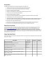
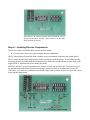
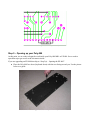
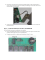
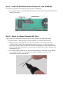
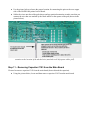
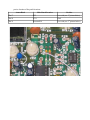
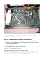
AtomaHawk Construction and Installation Instructions
Congratulations!
Congratulations on your purchase of the AtomaHawk retrofit kit. This kit provides your Poly 800 Mk1 or EX-800
with control over the three most common hardware hacks for this instrument. They are:
1. The “Moog Slayer” (or extreme resonance) modification.
2. The “FM-800” or DCO sourced VCF modulation.
3. The 12/24db filter slope switch.
The most important benefits of using this kit instead of the original hardware modification hacks are:
1. You don't have to drill holes in your synthesizer to obtain the benefits of these great modifications.
2. The settings of the new modifications are saved in patch memory for easy recall.
3. MIDI controller messages can be used to control the modifications.
4. The modifications can be influenced by LFO, EG etc.
5. If you have already carried out the original modifications, you can still install this kit and use the original
controls in tandem with the AtomaHawk kit.
Prerequisites
You MUST have already installed the HAWK-800 before you can install this kit. This kit will NOT work without
the HAWK-800 kit already installed.
To get further details on the Hawk-800 and AtomaHawk kits go to http://patrioticduo.tripod.com/hawk800/
WARNING and DISCLAIMER
You take full responsibility for any outcome, good, bad or ugly, when constructing, installing and using this
retrofit kit. Do NOT attempt to construct, install or use this retrofit kit unless you understand and are willing to
accept responsibility for any outcome that may result from your own attempts to construct, install and use this kit.
NOTE: This kit requires the removal of one component from the main Poly 800 or EX 800 printed circuit boards
(PCB's) and also requires soldering multiple wires into the main board of the instrument. This requires
electronics technician skills. If you do not have the skills required to remove components and patch in hook up
wire then you should have someone else do the job for you. Your local music store should be able to help you to
find a qualified technician in your area.
Safety First
NOTE: Remember to approach your work with care and appropriate safety precautions.
Before you Begin
It is critically important to make sure that you received all of the components in the kit and that none of the
components show any sign of physical damage. Check that you received all of the components in the quantities
mentioned below. Also visually inspect each component and ensure that there is no sign of any physical
damage.
Preparation
The basic steps involved in the successful completion of this project are:
1. Read these instructions and understand the steps and tasks required.
2. Check the kit for delivery of all components physically undamaged.
3. Obtain the needed tools and supplies.
4. Backup your Poly-800 Mk1 or EX-800 global, patch and sequencer data.
5. Construct the new retrofit board (AtomaHawk).
6. Open up the Poly-800 Mk1 or EX-800.
7. Remove the main board (KLM-596), remove capacitor C103 and then replace the main board.
8. Install capacitor C103 on the AtomaHawk board.
9. Remove the HAWK-800 board, install the new address decoder socket, install the address decoder and
attach the wire pair to the HAWK-800 board then replace the HAWK-800 board (and test the synth).
10. Attach wire sets to the AtomaHawk board.
11. Attach the wire sets to the main board and install the AtomaHawk board on its mounting point.
12. Test the three new modifications and then begin using your upgraded synthesizer.
Read the Instructions
It is very important that you read these instructions through to the end first before beginning any work. This
should give you a good understanding of the steps involved in the project. If you need assistance you can
contact [email protected] for additional explanation of any part of these instructions. This project
requires patience and about 1 hour to complete. You should plan to set aside 2 hours so that you have plenty of
time to focus on each task. Do NOT rush any step in this project. It is better to take extra time instead of ruining
your synthesizer or the retrofit kit.
Check the Kit of Parts
Check that you have received all of the parts in the kit. Use the list below and check off each line in the
“Received” column.
Description
Part No.
Quantity
Printed Circuit Board
AtomaHawk
1
Integrated circuit digital potentiometer
DS1666-10+
1
Integrated circuit 6 bit latch
74HC174
1
Integrated circuit digital switch
4053
1
One of eight decoder
74HC138
1
47Kohm ¼ watt resistor (marked with bands Yellow,
Violet, Orange, Gold)
-
1
10Kohm ¼ watt resistor (marked with bands Brown,
Black, Orange, Gold)
-
1
1Kohm ¼ watt resistor (marked with bands Brown,
Black, Red, Gold)
-
1
Shipped
Signal diode (small glass devices marked with thin red
band)
1N914
2
.1uF ceramic capacitor
-
1
14 pin DIP socket
-
1
16 pin DIP socket
-
3
Ribbon gray cable (two strands, length 15 inches)
-
2
Ribbon gray cable (16 strands, length 5 inches)
-
1
Jumper wire (24 gauge, length of about 12 inches)
-
1
PCB standoff (½ inch)
-
1
Nylon washer
-
1
Screw (self tapping)
-
1
Screw (M3 x 20mm)
-
1
If you find any parts missing or damaged contact [email protected] for assistance.
Required Tools and Supplies
To construct and install this kit will require (at minimum) the following tools:
1. Phillips screwdriver.
2. Small (2.5) flat blade screwdriver.
3. Small side cutter.
4. Small long nose pliers.
5. Suitable Soldering iron (around 20/40 watts with fine soldering tip).
You will need to obtain the following supplies:
1. Rosin core solder standard 60/40 formula for electronics work. Approx. 0.032” diameter.
Backup your Poly-800 Mk1 or EX-800 Patch and Sequencer Data
You should not lose your global, patches or sequencer data but it is a good idea to back them up.
Constructing the AtomaHawk Printed Circuit Board
At this point, you should have obtained all of the needed tools and supplies to carry out the entire
project. And you probably should have backed up your global, patch and sequencer data too (although
it is not actually necessary). You are now ready to construct the AtomaHawk PCB.
Step 1 – Prepare a work space
First, you need to prepare a workspace. Find a flat surface ( a kitchen table or work bench is
recommended) to work on. You will need a flat area about 1 meter square (3 feet x 3 feet).
Step 2 – Installing all Wire Jumpers on the New PCB
We are ready to begin soldering the wire jumpers onto the new board.
●
Use the diagram below to populate the board with all seven (7) wire jumpers.
●
When installing the jumpers, solder one end first and then make sure that you firmly pull the
other end of the jumper wire so that it is straight (long nose pliers are very useful for applying
the necessary force to straighten the wire out by pulling on the non soldered end). It is important
to ensure that the jumpers are installed straight so that they don't short out against each other.
Illustration 1: Location of Seven Wire Jumpers
Step 3 – Installing the IC sockets
We are now ready to install and solder all of the IC sockets.
●
Use the picture below as a guide to install the two 16 pin IC sockets and the one 14 pin IC
socket.
●
We recommend installing the sockets one at a time, solder two pins diagonally opposite. Ensure
that the socket notches are oriented correctly (see the picture below) and that all pins are
properly protruding through each PCB hole and make sure that the socket is seated correctly.
Then solder all of the remaining pins.
●
Double check to make sure that you have not accidentally bridged any pins and that all pins are
soldered.
Illustration 2: IC Socket Location and Orientation (16 Pin
sockets are at center and left, 14 Pin socket is on the right.
Note location of notches.
Step 4 – Installing Discrete Components
We are now ready to install the three resistors and two diodes.
●
Use the picture below as a guide to install discrete components.
NOTE: Ensure that you install the diodes with the correct orientation as shown in the picture below.
That is, ensure that the black stripes on the diodes are matched with the picture. If you printed out this
document in black and white then the orientation of the diodes may not be obvious so refer back to the
original PDF to determine the correct diode placement.
SPECIAL NOTE: Pay special attention to the location of each end of resistor R3. The first version of
the AtomaHawk printed circuit board was missing a specific location for installation of resistor R3
(47K ohm). As a result it is installed into the board using a spare position on the row of pins that extend
wires onto the main board.
Illustration 3: Location of Resistor R3 (47K ohm)
Step 5 – Opening up your Poly-800
At this point, we are ready to begin the work inside your Poly-800 MK1 or EX-800. So we need to
open them up to get access to the electronics inside.
If you are upgrading an EX-800 then skip to “Step 5(a) – Opening the EX-800”.
●
Place the Poly-800 face down (keyboard down) with the rear facing toward you. Use the picture
below as a guide.
Illustration 4: Removing the Case Screws from the Poly-800
●
Remove the 3 short screws from the front edge of the keyboard (numbered 1 to 3 in the picture).
●
Remove the 9 medium length screws from the perimeter of the keyboard (numbered 4 to 12).
●
Remove the 4 threaded screws from the bottom of the keyboard (numbered 13 to 16).
●
Set the screws aside somewhere safe where they will not be lost or misplaced.
●
Carefully hinge away the bottom section of the Poly-800 bringing it toward. Ensure that you do
not strain the wire bundles that join the bottom section to the top section of the keyboard. See
the picture below.
Illustration 5: Hinging Open the Two Halves of the Poly-800 MK1
●
Remove the two guitar strap pegs and set them aside somewhere safe where they will not be
lost or misplaced.
Step 5(a) – Opening the EX-800
If you are upgrading an EX-800 then do the following.
●
Remove the four (4) small black screws from the rear of the unit.
●
Remove the four (4) small black screws from the two sides of the unit.
●
Set aside the screws in a safe location where they will not be lost or misplaced.
NOTE: No picture of the EX-800 is provided.
Step 6 - Removing the main board
●
Locate the main board and disconnect cable assemblies shown in the picture below labeled as
A,B,C,D,E, F and G. Use care as you remove the connectors so as to avoid bending any of the
rows of pins.
Illustration 6: Remove all Cable Assemblies Shown A through G
●
Locate and remove the screws that secure the main board and secondary board (marked as A to
I in the photo). Set aside the 9 screws in a safe place where they will not be lost or misplaced.
●
Carefully remove the
main board (along with
the RFI shield) and
secondary board all
together. If you are
working on an EX-800
then you will also need
to unscrew and remove
the MIDI thru board too.
●
Set the Poly-800 Mk1 or
EX-800 units aside in a
safe location where they
will not be damaged.
●
Set the main and
secondary board up in
your work area.
●
Desolder the connection from the main board to the RFI shield. Set aside the shield where it
won't be lost or misplaced. Disconnect the shield by desoldering the resistor that connects to the
main board tab (see picture below).
●
Set the main board aside for the moment. We will come back to it as soon as we look after the
HAWK-800 board.
Step 7 – Install the Additional IC Socket in the HAWK-800
The HAWK-800 board requires an additional socket installed.
●
Remove the HAWK-800 board from your synthesizer by first removing the two header cable
assemblies and then physically remove the HAWK-800
●
Using the picture below as a guide, install the additional 16 pin IC socket.
Illustration 7: Installing the Additional IC Socket on the HAWK-800
Step 8 – Install the Additional Address Decoder IC in the HAWK-800
We should now install the new address decoder chip in the HAWK-800.
●
Use the picture below to install the additional address decoder (74HC138) into the HAWK-800
printed circuit board.
Illustration 8: Install the Additional Address Decoder
Step 9 – Attach the Address Decoder Wire Pairs
A pair of wires will connect the HAWK-800 device select signals to the AtomaHawk board.
●
Find one of the 15 inch long gray wire pairs (hopefully, we will only need one pair).
●
Strip both wires at both ends so that you have less than about one sixteenth of an inch
(1-2mm's) of bare strands. The copper strands in the gray wire are very easily severed so it
takes some real care to strip the insulation off while not damaging the copper strands inside. A
second 15 inch length of paired gray wires has been provided in case you have difficulty with
stripping these wires.
●
Use a black marker to mark one wire at each corresponding wire end so that you can identify
one wire from the other at each end. Make sure that you mark the same wire at each
corresponding end (See picture below).
Illustration 9: Mark One Corresponding Wire at Each End
●
Use the picture below to locate the proper location for connecting the pairs to the rear copper
side of the HAWK-800 printed circuit board.
●
Solder the wires onto the solder pads shown and pay particular attention to make sure that you
connect the wire that was marked by the black marker to the square solder pad (shown in the
picture below).
Illustration 10: Attach the Grey Pair of Wires to the Underside of the HAWK-800. Pay special
attention to the location of the marked wire (attached to the left square solder pad).
Step 11 – Removing Capacitor C103 from the Main Board
We need to remove capacitor C103 from the main board (do not discard the capacitor).
●
Using the picture below, locate and then remove capacitor C103 from the main board.
Illustration 11: Locate Capacitor C103 and Remove (Do NOT discard this capacitor)
Step 12– Install Capacitor C103 and Decoupling Capacitor
We need to install capacitor C103 and the .1uF decoupling capacitor in the AtomaHawk board.
●
Using the picture below as a guide, install capacitor C103 and the supplied .1uF capacitor into
the AtomaHawk board.
●
IMPORTANT: If you are installing the AtomaHawk into a EX-800 then it is necessary to lean
the C103 capacitor over as far as you can so that it does not interfere with the display board.
●
Then install the three IC's. The 74HC174 at left, the CD4053 in center and the DS1666 at right.
Pay special attention to make sure that you install the chips with their orientation as shown in
the picture below.
Illustration 12: Install capacitor C103, the decoupling capacitor and the three IC's
Step 13 - Attaching the AtomaHawk side of the Hook Up Wires
Now we must attach the hook up wires that will connect the AtomaHawk board to the main board.
●
Use the five inch long group of gray wires.
●
Split off a group of six (6) wires.
●
Split off a single wire (1).
●
Split off an additional group of three (3) wires.
●
Split off a pair of wires (2).
●
Split four single wires.
●
Strip all of the wires at each end so that only a short one sixteenth (1-2mm's) is exposed at each
end. Stripping these wires can be quite challenging. It is necessary to use a very light pressure
on the plastic insulation so that as you pull the wire you do not end up cutting the copper
strands off with the insulation. An extra pair of wires is supplied with the kit so that you can
practice a little or use them if you have difficulty with the stripping.
●
Tin all of the wires at both ends. Make sure that you trim the length of the strands after they
have been tinned so that only about 1-2mm's of wire is exposed.
●
Connect the wire groups and single wires as shown in the picture below. Note that the pair of
wires shown connected at pins 7 and 8 are the two wires that you previously connected to the
HAWK-800. Make sure that the previously black marked wire is connected to the left hand pad
as shown in the picture.
●
Use the picture below as a guide.
Step 14 - Arrange your workspace
Now we will attach the groups of wires to the main board. To do this, we will arrange our workspace to
make it as easy as possible to make the connections. Bring all three boards into your workspace as the
picture below shows.
Illustration 13: Arrange your Workspace this Way
Step 15 - Attaching the First 6 Hook Up Wires to the Main Board
Now we will attach the groups of wires to the main board starting with the first six. For all patching
into chips (IC's) you should tin the pin on the chip first before attempting to patch the wire onto the pin.
●
Attach the first group of six wires as follows:
AtomaHawk
Main Board IC
Main Board Pin
Pin 1
IC21
Pin 24
Pin 2
IC21
Pin 9
Pin 3
IC21
Pin 10
Pin 4
IC21
Pin 11
Pin 5
IC21
Pin 12
Pin 6
IC21
Pin 21
Step 16 - Attaching the Fours Wires to the Main Board
The next two wires in order (pins 7 and 8) should already be connected to the AtomaHawk and
HAWK-800 boards. So now we move on to the next single wire and three wires that need to be
connected to the main board.
●
Attach the next single wire and following three wires as follows:
AtomaHawk
Main Board IC
Main Board Pin
Pin 9
IC4
Pin 4
Pin 10
IC1
Pin 6
Pin 11
IC1
Pin 5
Pin 12
Capacitor 103 (see picture)
Negative pole position (upper)
NOTE: IC1 is installed in a socket. We recommend tinning the pins and attaching the hookup wires
directly to the IC pins while the IC is installed in its socket. See picture below.
Illustration 14: Filter IC Hookup Detail - jumper connected to high position of C103
Step 17 - Attaching the Next Pair and Single Wires to the Main Board
Now we move on to the next pair of wires and single wire that need to be connected to the main board.
●
Attach the next single pair and single wire as follows:
AtomaHawk
Main Board IC
Main Board Pin
Pin 13
IC4
Pin 7
Pin 14
IC5
Pin 7
Pin 15
Resistor R21
Upper side
The connection of pin 15 to Resistor R21 is quite difficult because R21 is a very small resistor. Use the
picture below to spot the location and you may need a magnifying glass to patch in the wire.
Step 18 - Attaching the Last Three Single Wires to the Main Board
Now we move on to the last three wires that need to be connected to the main board.
●
Attach the last three wires shown in the table below and refer to the pictures for details on the
precise location of the patch locations.
AtomaHawk
Main Board Location
Position
Pin 17
R23
Low side (see 1st picture below)
Pin 18
IC21
Pin 8
Pin 21
Resistor R21
Low side (see 2nd picture below)
Illustration 15: Pin 17 from the AtomaHawk connects to the Low Side of Resistor R23
Illustration 16: The Connection from Pin 21 on the AtomaHawk to Resistor R21 (lower side)
Step 19 - Replace the Main Board into your Synthesizer
First, double check your work. We recommend that you go back over all of the steps and double check
that you have built the AtomaHawk board correctly, that you have installed the two wire connection to
the HAWK-800 board correctly and that you have correctly patched all wires between the AtomaHawk
and the Main Board.
●
Reinstall the Main Board back into your synthesizer.
●
Refer to the picture below when installing the AtomaHawk board into a Poly-800MK1. Using
the nylon washer, the supplied self tapping screw and nylon standoff, install the AtomaHawk
board.
●
IMPORTANT: If you are installing the AtomaHawk into an EX-800 then you will use the M3 x
20 mm screw and PCB nylon stand off but DO NOT use the nylon washer.
Illustration 17: Use the Plastic Standoff, Supplied Screw and Washer to Install the AtomaHawk.
NOTE: (this picture is actually wrong since the washer should NOT be used in the EX-800. Also, C103
has NOT yet been leaned over to the right. If you were to put the cover on with C103 sticking up as it is
shown then the EX-800 would not close properly.
Step 20 - Replace all Cable Assemblies, Close Up and Test
●
Replace the two ribbon cable assemblies between the main board and the HAWK-800.
●
Replace all of the cable assemblies between the upper and lower sections of your synthesizer
and then close up the synthesizer.
●
Solder the RFI shield connection back to the main board.
●
Power on the synthesizer and test for correct operation.
Step 21 - Test the New Modifications
We now need to test that each modification feature works as it should.
WARNING: Before testing the Moog Slayer modification, you should turn your speakers or head
phones down low. The Moog Slayer is capable of producing loud resonant tones that could damage
your equipment. Set the volume low first before testing the Moog Slayer.
●
You can check that the Moog Slayer (extreme resonance) modification operates correctly by
setting extended parameter 58 to 1 and setting extended parameter 51 to 99. Setting extended
parameter 58 to zero (0) turns the extreme resonance off, setting extended parameter 58 to one
(1) turns Moog Slayer on.
●
You can check that the FM-800 function operates correctly by setting extended parameter 61 to
maximum (99) and press and hold at least 2 notes. The sound should be highly distorted while
two notes are sounding. It may also be necessary to set parameter 68 to zero (0) to get the
correct operation.
●
You can check that the 12/24db per octave filter switch operates correctly by changing extended
parameter 48 from 1 to 2 and back again. The filter slope should change between the two
different filter slope modes.
Troubleshooting
●
If your Poly-800 or EX-800 does not operate at all then immediately switch off your synthesizer
and immediately check the following:
1. Make sure that the orientation of the chips is correct.
2. Check the AtomaHawk PCB again. Look for any solder bridges or any pins or components
that are not soldered.
3. Check for solder bridges or incorrect patching of the following patch wires.
4. Make sure that the two signal diodes are oriented correctly.
AtomaHawk
Main Board IC
Main Board Pin
Pin 1
IC21
Pin 24 (+5V)
Pin 5
IC21
Pin 12 (GND)
Pin 9
IC4
Pin 4 (-5V)
●
If the synthesizer powers up OK but none of the modifications operate then check the
following:
1. Make sure that resistor R1 is 10K ohms (brown, black, orange bands).
2. Make sure that the orientation of the IC1 (74HC174) is correct.
3. Check for solder bridges or incorrect patching of the following patch wires.
AtomaHawk
Main Board IC
Main Board Pin
Pin 2
IC21
Pin 9
Pin 3
IC21
Pin 10
Pin 4
IC21
Pin 11
Pin 6
IC21
Pin 21
Pin 18
IC21
Pin 8
4. Check for solder bridges or incorrect patching of the two wires that run from the
HAWK-800 to the AtomaHawk. Double check to make sure that the wires correspond at
each end.
Atomahawk
HAWK-800 board
Function
Pin 7
HAWK-800 IO Device Select 0
74HC174 latch device select
Pin 8
HAWK-800 IO Device Select 1
Digital POT device select
●
If the synthesizer powers up OK but the Moog Slayer modification does not operate then check
the following:
1. Make sure that the orientation of IC2 (4053) is correct.
2. Make sure that resistor R3 is installed on the AtomaHawk board in pins 16 and 21.
3. Make sure that the following patch wires are connected correctly.
Atomahawk
Main Board
Position
Pin 15
Resistor R21
Upper side
Pin 21
Resistor R21
Low side
●
If the synthesizer powers up OK but the FM-800 modification does not operate then check the
following:
1. Make sure that the orientation of IC3 (DS1666) is correct.
2. Make sure that resistor R2 is 1K ohm (brown, black, red bands).
3. Make sure that the following patch wires are connected correctly.
AtomaHawk
Main Board
Position
Pin 13
IC4
Pin 7
Pin 14
IC5
Pin 7
Pin 17
R23
Low side
●
If the synthesizer powers up OK but the 12/24db/octave filter switch does not operate then
check the following:
1. Make sure that the orientation of IC2 (4053) is correct.
2. Make sure that C103 is installed on the AtomaHawk board.
AtomaHawk
Main Board
Main Board Pin
Pin 10
IC1
Pin 6
Pin 11
IC1
Pin 5
Pin 12
Capacitor 103 (see picture) Negative pole position (upper)
●
If none of the above provides a way for you to correct the problem then some limited additional
technical assistance can contact be obtained by contacting us at [email protected].
The assistance we can offer is limited but we will do the best we can to assist you in the
installation and operation of the AtomaHawk kit.
What's Next
Now that you have successfully constructed and installed the AtomaHawk kit you can download the
latest User Manual from http://patrioticduo.tripod.com/hawk800. The user manual provides instruction
on how to make the most of your AtomaHawk kit.
Appendix 1 – AtomaHawk Pin Allocation and Function
AtomaHawk
Main Board
Main Board Pin
Function
Pin 1
IC21
Pin 24
+5 Volt power
Pin 2
IC21
Pin 9
Data bus D0
Pin 3
IC21
Pin 10
Data bus D1
Pin 4
IC21
Pin 11
Data bus D2
Pin 5
IC21
Pin 12
0V - ground
Pin 6
IC21
Pin 21
Write
Atomahawk
HAWK-800 board
Function
Pin 7
HAWK-800 IO Device Select 0
74HC174 latch device select
Pin 8
HAWK-800 IO Device Select 1
Digital POT device select
AtomaHawk
Main Board
Main Board Pin
Function
Pin 9
IC4
Pin 4
-5 Volt power
Pin 10
IC1
Pin 6
24db/octave filter tap
Pin 11
IC1
Pin 5
12db/octave filter tap
Pin 12
Capacitor 103
(see picture)
Negative pole position
(upper)
Filter in tap
AtomaHawk
Main Board
Position
Function
Pin 13
IC4
Pin 7
DCO1 waveform tap
Pin 14
IC5
Pin 7
DCO2 waveform tap
Pin 15
Resistor R21
Upper side
Moog Slayer tap (1 of 2)
AtomaHawk
Main Board
Position
Function
Pin 17
R23
Low side
DCO into VCF
Pin 18
IC21
Pin 8
Address Bus A0
Pin 21
Resistor R21
Low side
Moog Slayer tap (2 of 2)