1
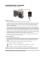
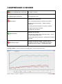
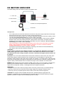
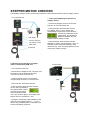
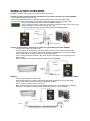
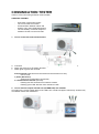
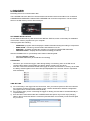
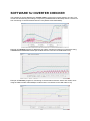
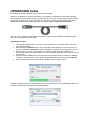
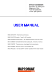
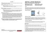
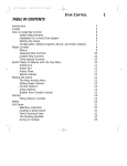
INVERTER CHECKER
Equipment for testing and diagnostic of the
FUJITSU-GENERAL
inverter split systems
USER MANUAL
Preliminary version (August 2013)
UTQ-COMP - checker for DC compressors
UTQ-DCFM - checker for DC fan motors
UTQ-STPM - EEV stepper motor and louver motor checker
UTQ-COMSIM - simulation of indoor and outdoor units, monitoring of communication
UTQ-COMTEST - checker of correct unit wiring and their communication
UTQ-LOGGER - recording device for communication data
UTQ-UPGC - usb data cable for software upgrade of the inverter checker modules
UTQ-CASE - carrying case
COMPRESSOR CHECKER
Functional testing of inverter DC compressors
Preparation for testing:
•
Disconnect the cables of the compressor from the outdoor unit PCB.
•
Use an ohmmeter (with a range of megaohms) for checking possibility of short circuit or leakage
between the connector contacts and the motor frame. All values must be outside of top of the
range of the ohmmeter. Otherwise, the motor is defective. Do not continue with testing, the
checker could be damaged.
•
Check the resistance between the compressor leads with ohmmeter. The value of resistance of
the motor winding can be, depending on the compressor, in the order of tenths to whole Ohms. It
is essential that the resistance of all winding showed the same value. If any value is significantly
different, the engine is defective. Do not continue with testing, the checker could be damaged.
•
Connect the power cord lead to the 230VDC power supply of the tester (fused at least with 16A
circuit breaker). The switch ‘’POWER’’ must be in position ‘’O’’, switch ‘’TEST’’ in position ‘’STOP’’
and the desired speed of compressor must be set by switch in position ‘’LOW’’
•
Connect the cable of the checker to the three connectors of compressor windings and ground
clamp to the frame or chassis of the outdoor unit.
Test of the compressor
1. Turn on the tester by switch ‘’POWER’’
2. After pressing the TEST switcher, the compressor will start and its speed is gradually increasing
from zero to 50% of the maximal speed. LED during the test alternate between red and green.
3. Please do check the running compressors check by hearing in case that shows any unusual
noises.
4. After the test of the compressor, the final result is indicated by LED ‘’Status’’
Continuous green light … compressor is OK
Red flashing … compressor is faulty (detailed errors identification - see Table)
Green flashing … checker error (detailed errors identification - see Table)
In case of a positive test result from position ''LOW'‘, the test can be repeated again with a speed
switch in position '‘HIGH'‘. This mode will increase speed gradually up to the maximum of 100%.
ATTENTION! Before each repetition of the test is necessary wait at least three minutes until the
pressures in the refrigerant circuit gets balanced again!
COMPRESSOR CHECKER
RED and GREEN flashes alternately
GREEN lights continuously
The TEST is running
The compressor is OK
ERROR of the compressor :
RED flashes
2x it’s not possible reach the maximum rotor speed
3x phase currents asymmetry - different winding
resistances
4x winding insulation resistance to ground <1MOhm
5x supply current limit exceeded
6x compressor spin failed
ERROR of the Checker:
GREEN flashes
2x DC bus low voltage +350 V (less than 300V) – check
the power supply of the tester
3x high temperature of heat sink – please leave the tester
cool down
RED flashing rapidly
Firmware of checker is faulty – upgrade was not
successful. In this case, it is necessary to repeat the
upgrade again (see chapter - UPGRADING cable).
Testing software – see the example of testing with the result: Compressor is OK
DC MOTOR CHECKER
Functional testing of DC fan motors of indoor and outdoor units
2 - colour LED
Function switcher
The connector box
Tested DC motor
Main switch
Controller of manual speed adjustment
Power lead
Test process:
-
-
-
Turn off the power of the unit and wait a few minutes for the power supply capacitors to discharge.
Disconnect the DC motor connector from the control PCB of the unit.
Turn the rotor of the fan by hand. If you can feel a significant resistance, the motor is faulty. In that
case, do not continue with testing, the checker could be damaged.
Use an ohmmeter (with a range of megaohms) for checking possibility of short circuit or leakage
between some of the motor leads (red, black, white) and the motor frame. All values must be
outside of top of the range of the ohmmeter. Otherwise, the motor is defective. Do not continue
with testing, the checker could be damaged.
Use an ohmmeter to check the resistance between each motor power connections (red, black,
white) - must not show measurable resistance. Otherwise, the motor is defective. Do not
continue with testing, the checker could be damaged.
Connect the motor to the checker. During the connecting, the checker must be switched off by
main switch and the function switcher in position 0!
CAUTION!!
Plug the motor connector to the mating connector in connector box. Attention! Connectors of
certain motor types have colour coding in reverse order. Make sure that the colour of cable
wire matches the colour coding of engine connector; otherwise the engine and the checker can
be damage.
AUTO test: Turn on the main switch and then the function switcher to TEST mode. The motor spins
continuously and then reduces speed to zero. During the test, the LED flashes in red and green
alternately. Keep checking if the motor does not have any vibration, or unusual noises. If the LED after
the test is lit in solid green, the engine is electrically fine. If the LED is lit in solid red or flashing red, the
engine is faulty. If the automatic test is successful, the engine can be tested in a manual mode.
MANUAL test: Change the function switcher to MAN. In this mode, you can increase or decrease the
speed by control manual settings. Test the motor gradually throughout of his speed range. If the
engine does not respond correctly, or LED lights up red, the engine is defective.
WARNING!!
- During the test, the motor must be properly fixed to avoid any personal injury or material damage.
- And also do not touch the connectors! There is high voltage and a danger of electric shock.
- Tester may use only competent person which is able to work with electrical equipment.
CAUTION!! The engine must be loaded during the test, if possible with the original fan rotor
(propeller). Unloaded motor may (depending on type) show during acceleration twitching, irregular
operation, vibration or engine can be evaluated by tester as faulty.
STEPPER MOTOR CHECKER
Functionality testing of motors of electronic expansion valve (EEV) and also the louver stepper motors.
The connector box
1. Testing and adjusting the position of
stepper motors:
- Connect the stepper motor to the checker
and turn on the main switch ON.
Louver motor
LCD display
- Press the button FN and select function
EL.CHECK, press +, then checker will
automatically check all four motor windings.
The result is displayed on the
LCD display. Any significant
difference between the four
results means that EEV is faulty.
Function selection
The manual control
Main switch
Power lead
2. Monitoring the operation of stepper
motors controlled by PCB unit:
- Press the button FN and select function
MANUAL or FAST. Use the buttons + and – to
manually control motorized rotating in both
directions (e.g. close and opening EEV).Check
if the motor rotates correctly.
Control PCB
- Turn off power to the unit.
- Disconnect the stepper motor connector from
PCB and connect instead the flat cable
connector from the connector box.
- Cable of stepper motor is connected to
corresponding connector in connector box.
- Power ON the unit and the checker.
- Press the button FN and select function
AUTO. Now is possible to
see and track the number
of pulses of the stepper
motor controlled by the
unit. If you need to open or close EEV more,
please use for it the buttons + and - During the monitoring is also possible to see
status of the excitation pulses (- - - -) but in
case of any prohibited pulse combination, the
checker will display symbol E.
EEV
SIMULATOR CHECKER
Simulator of indoor and outdoor unit, communication monitoring
Testing of inverter outdoor units by simulations of the indoor unit (poss.use with LOGGER)
- Turn off power supply of outdoor unit.
- From the terminal, designed for connecting cable, disconnect the communication cable.
- Connect the tester to the outdoor unit through a terminal intended for the connection cable.
- On the tester set the function switcher to INDOOR position.
- Turn on power of outdoor unit and in the menu set the right model of the unit (or type
of communication AOYA, AOYD, AOYR, AOY, DX)
- Now the outdoor unit can be controlled by SIMULATOR CHECKER
Black (L)
White (N)
Red (C)
To indoor unit
Outdoor unit
terminal
Power supply cable
Testing of indoor unit by simulation of outdoor unit (possibility use with LOGGER)
Turn off power supply of outdoor unit.
From the terminal, designed for connecting cable, disconnect the communication cable.
Connect the tester to the indoor unit through a terminal intended for the connection cable.
On the tester set the function switcher to OUTDOOR position.
Turn on power of indoor unit and in the menu set the right model of the unit (same as for
indoor mode)
Now the indoor unit can be controlled by SIMULATOR CHECKER
Black (L)
White (N)
Red (C)
Indoor unit
terminal
Cable to outdoor unit
Monitoring of communication between indoor and outdoor unit (possibility use with LOGGER)
Turn off power supply of outdoor unit.
Connect the tester to the indoor unit through terminals, designed to connect the cable.
On the tester set the function switcher to MONITOR position
Turn on power of outdoor unit + indoor unit
Now you can monitor the communication between the indoor and outdoor unit by program
Simulator, connected to checker over the USB data cable or use a LOGGER.
Black (L)
White (N)
Red (C)
Outdoor unit
terminal
Indoor unit
terminal
Tester is possible to connect either to indoor or outdoor unit
COMUNICATION TESTER
Tester of correct unit wiring and their communication
USED FOR TESTING:
-
Connection of the power supply
The correct cable connection.
Communication between indoor and
outdoor unit in the individual directions.
The functionality of external outputs of
modules UTI-INV-xxx and UTI-EXP.
1. Test of connection and communication:
a. Connect the crocodile clip from tester to the ground terminal or ground of the IU or OU.
b. Attach the probe tip to the testing terminal.
c. Watch glow of green and red LED:
N zero terminal (white wire from the terminal to the electronics of unit):
LED is not lit
L phase (black wire):
Green and red LED lights continuously
C communication terminal (red wire):
Flashing red LED: direction from inside to outside
Flashing green LED: direction from outside to inside
2. Test of external outputs UTI-INV-xxx (ON ERR DEF) and UTI-EXP:
According to the current output either of the LED is off, or both LED lights continuously. Another way
of indication means the malfunction.
LOGGER
Recording device for communication data
The LOGGER scans the data from communication line between indoor and outdoor unit or between
COMPRESSOR CHECKER / SIMULATOR CHECKER and connected compressor / unit and saves
them on the SD memory card for future analysis.
SOFTWARE INSTALLATION
On the attached SD memory card can be find a INSTALL.EXE file, which is necessary for installation
of all inverter checker programs into your computer.
These programs are following:
-
COMPTEST- program used for display the status information during the testing of compressor
SIMULATOR – monitoring communication data between IU a OU
UPDATER – possibility upgrade the modules or programs for INVERTER CHECKER
CHECKER viewer – display all saved data from testing procedures
After the installation are on your desktop also created a following data:
-
manuals (English / Czech)
CHECKER data folder (for saved files from testing)
ATTENTION:
•
•
Whenever you connect the logger, either during testing or monitoring, then on the SD card is
created a file matching a given date (see picture below, it means July 23, 2013).
And also it should be remembered that if the logger is used a several times in one day, all the data
are always saved together into a same file!! (but displayable in the checker viewer in separated
time subfolders)
TIME SETTING
a) if it is necessary in the logger set the current time, then you need to upload on SD card a time.txt
file (could be created in windows notepad), which contains desired time and date configuration
(see figure below / it means 24.6.2013,18:39:00)
b) the next time when you are connecting the logger for testing, the time will be set automatically to
required settings
c) but it should be remembered that the LOGGER itself holds power only for two days (charging
takes in about 10 minutes after the connection) and therefore it is necessary to set the time again
as you need it
SOFTWARE for INVERTER CHECKER
The example of records displayed by checker viewer. A total of four entries stored in one day. Two
records are stored during the testing of compressor (COMPRESOR CHECKER) and two records are
from monitoring of communications between units (SIMULATOR CHECKER).
Example of comptest program for displaying the graphic results from testing of compressors using
COMPRESSOR CHECKER module (the module must be connected via USB cable to PC)
Example of simulator program for monitoring of communication between indoor and outdoor units
using the SIMULATOR CHECKER(the module must be connected via the USB cable to PC)
UPGRADING Cable
Data cable for software upgrade of the inverter tester modules
Whenever is released a new firmware update, it is possible to do upgrade by connected upgrading
cable together with the updater program (needs internet connection). This information about UPDATE
will be send by email to all owners of inverter checker. Due to repairs and improved functionality of
INVERTER checker and programs package, this regular update is highly recommended!!
There is not any upgrade possible without a connected and properly installed UPGRADING cable!!
(Even for the programs in the PC itself)
Upgrading procedure:
1. The upgrading cable plug in to usb port on your notebook or PC and wait until is usb driver
successfully installed.
2. Start the program Updater and if is any new update of the software on the server then you
can press the button Download to start an installation of updates for the programs in your pc.
3. Second step is to check if your module has a newest firmware already installed or not.
Connect the cable to the module which you need to upgrade (keep the top of cable as you see
on the label).
4. Press the button Connect to see what is the current firmware inside of module, if is different
compare to firmware on the server. Select the desirable FW and press the button Upgrade.
5. After the writing procedure is the module updated to latest firmware version.
During the firmware upgrade of the hardware device, do not disconnect the UPGRADING cable!! This
could cause irreversible damage to the updated module!!