1
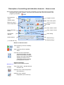
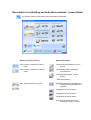
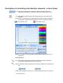
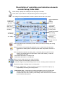
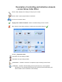
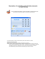
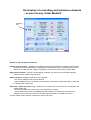
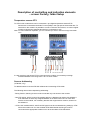
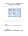
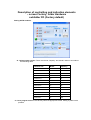
Accessory of
ATW-C-INV module
USER
MANUAL
ATW - Touch panel
ATW - SW
APPLICATION
ATW-SW program and its modification installed in touch display of ATW – Touch Panel are intended for
usage, setting and monitoring of heating and cooling equipments via inverter outdoor Fujitsu unit
and are equiped with inteligent controlling ATW-C-INV module.
APPLICATION OPTIONS
-
Heat pumps air to water
Chillers
Cooling and heating system with AHU units with exchangers for direct evaporating of refrigerant
Systems of technological cooling with application of industrial evaporators
INSTALATION
ATW-SW program:
1.
2.
3.
4.
5.
Create separate folder in that PC where the program is started up (for example in folder
Documents, Program Files etc.) and copy there the file InverterV2.exe.
Create shortcut of this file on desktop.
At the first start up of program the info message is appeared: Application key is not correct in
InverterV2.ini. Please contact your distributor. Application ID is xxxxxxxxxxx
Send this ID to your distributor by email and he will generate the Application Key. Then close this
message.
Insert the code sent from your distributor to appropriate place in InverterV2.ini file which was
created in program folder during its first start up. Save the modified InverterV2.ini.
Upgrade of ATW-SW program: In case of the new program version availability the upgrade is possible.
The old InverterV2.exe file in program folder can be replaced by the new one without generation of
the new code and modification of InverterV2.ini.
ATW-Touch panel:
Program is already installed in contoll panel.
Program upgrade: In case of the new version program availability, please, contact your distributor.
WAY OF CONTROL
Function possibilities of both controllers are identical except of minor differences stated by the used
display equipment or the way of its control. In the text possible differences will be mentioned.
ATW-SW is controlled by the mouse when the cursor is placed on the approriate controlling element and
selected option is confirmed by the left button.
ATW-Touch panel is controlled by finger touch on the approriate displayed controlling element, option is
confirmed by the colour change.
STARTUP AND TERMINATION OF CONTROLLER PROGRAM
STARTUP:
-
ATW-SW is activated by tapping the icon of ATW-SW program.
ATW-Touch panel is usually supplied directly from the controlling equipment, so it is activated
automaticly after equipment supply is switched on.
TERMINATION:
-
ATW-SW: close the screen of the program.
-
ATW-Touch panel: power supply switch-off
Description of controlling and indication elements – Home screen
After program startup the preliminary Home screen is appeared. This one will provide you with basic
information about system operation. This screen can be entered also from other section of the
program by the button
Information box
about
„System status“
Program version
Buttons to correct
Indoor temperature
Buttons of manual
control:
Time of the system
Enter „Detail“ screen“
Enter preliminary
screen
Enter „Graph“ screen
User section
„Monitor“
Enter setting
Systém datas )*
Graph saving )*
)* at ATW-SW, only
Buttons of manual control:
„Start“ switching on from the standby
status
„Stop“ switching off in the standby
status
Correction of indoor temperature
„Adjust temperature“. By these
buttons it is possible to change
setting of the indoor temperature
stated by the thermal curve.
Temperature shift is presented
by the graphical scroll bar.
ATW Panel 1.14
11:29:06
System information:
Version of the software program
Time of the system – identical with the
set time in PC
Indication of the „Indoor temperature“
(ETS-B sensor)
Indication of the „Outdoor
temperature“ (ETS-H sensor)
Graph printing )*
Description of controlling and indication elements – screen Home
box „System status“
Information box „System status“ provides basic information about immediate status of the
system through graphic symbols:
„Heating“ mode is set
„Cooling“ mode is set
Automatic defrosting of outdoor
unit in heating mode
Compressor is running
Compressor stops
Program is in mode of heating of
heating water by the heat pump
Heating of heating water by
additional source – lower step
Heating of heating water by
additional source – higher step
Heating of DHW by heat pump
Heating of DHW by the heater in
tank
Current regulation request for
compressor output in % of its
maximum output
Mode of temperature reduction (by
timer or external signal)
System blocking by the external
signal during high el. tarrif
Description of controlling and indication elements - screen Detail
By „Detail“ button box with further system information is displayed:
Buttons for manual control:
System information:
„Cool“ system is switched in cooling
mode
„Heating water temperature“ (ETS-C
sensor)
„Heat“ system is switched in heating
mode
„Hot domestic water temperature“
(ETS-D sensor)
„Exchanger temperature“ (ETS-A
sensor)
„Other temperatures“:
Note: Non-active buttons are grey.
Requested equithermal temperature of
heating water (calculated by the
regulator)
Temperature of ETS-E sensor
Temperature of ETS-F sensor
Temperature of ETS-G sensor
Note: Non-connected sensors are
indicated by display of -0,1°C
Description of controlling and indication elements - screen Graph
By „Graph“ button the graph box is displayed. Measured system values are
displayed in time section of one day in range from 00:00 till 24:00 o´clock.
This button displays calendar where date of appropriate day of measurement is
selected.
Buttons with curve description of single parametres enable to switch off display of
single graphs. Display status of appropriate curve is indicated by symbols:
Curve display is ON
Zo Curve display is OFF
Buttons „Auto scale Y“ and „Auto scale X“ help to depress empty sections of the
graph area
Zoom functions:
Any graph section is displayed by selection of relevant area and by pulling the
mouse askew downwards from the left to do right.
Return to the basic scale by pulling the mouse askew upwards from the right to the
left.
Graph is saved by button „Save chart“ )* Graph is printed by button „Print Chart“)*
)* at ATW-SW, only
Descritpiton of controlling and indication elements
– screen Setup, folder Heat
Button „Setup“ displays user settings for the heat pump air to water
Button „Heat“ opens folder to set temperature regulation of heating water.
The change of numeral parameters is made by arrows and save with „Set“ button.
Parametres of
equithermal
regulation
Switching between
winter and
summer mode
of heating
Indoor temperature
limits:
Heating
Cooling
Temperature
attenuation:
Heating mode
Cooling mode
Arrows for numeral
value setting
Output limit:
for heating
Temperature to
switch-off
the heat pump
for cooling
Saving of the set
Values
Indoor temperature limits measured by ETS-B sensor (if is used) for heating and cooling
operations.
Setting of 6 points of the equithermal regulation curve. In single boxes the requested
temperature of heating water correspoding with outdoor temperature „Outdoor“ is
set.
Value of reduced temperature of heating water, activated by the timer (at ATW-Touch
panel) or by external signal (on input ON2 of ATW-C-INV module), in case the
Touch panel is not used.
- Temperature attenuation in heating mode
- Temperature attenuation in cooling mode
Button to switch winter and summer mode of heating:
- In winter program all used heating circuits are active.
- In summer program only DHW heating is active. Circuit of heating water is switched off.
Temperature setting of heating water for cooling mode.
Output limit „Power limit“ – setting of maximum request for compressor output (in %)
independently for heating and cooling modes.
„Total bivalent limit“ – Value setting of outdoor temperature to turn off the heat pump
function completely. Heat pumps is in standby status untill the temperature is
increased above this value. Heating of the heating water under this value is ensured
by the bivalent heating source.
Description of controlling and indication elements
– screen Setup, folder Timer
Button „Setup“ displays user settings of heat pump air to water
Button „Timer“ opens folder for week timer setting.
Arrows of time settings for decline start and stop in active box „from“ and „to“
Button to copy the time item „from“ to „to“ area and jump to this area
Button to erase the time item
Timer on – Button to activate timer:
active
inactive
)* Decline: shift of the equithermal curve by the value which is set in the box „Setup“,
folder „Heat“
Description of controlling and indication elements
– screen Setup, folder Water
Button „Setup“ displays user settings of heat pump air to water
Button „Water“ opens program folder to heat DHW
Arrows to set numeral values
Supply water enabled / Disabled – Button to activate heating function of DHW
Set – Button to save setting. Saving is confirmed by the symbol change to
Window „Temperature limit“:
Temperature to start heating of DHW
Temperature to stop heating of DHW
„Power limit“ – limitation of maximum compressor output in heating mode of DHW
„Time limit“ – limitation of DHW heating period by the heat pump. If the reqeusted
temperature is not reached within this period for switching off the DHW heating, the
electric heater in tank is switched on automatically.
Description of controlling and indication elements – screen Setup,
user setting of the system
Button „Setup“ displays user settings of heat pump air to water
Button to enter the user setting of the system.
Afterwards the following screens can be displayed: Data, Date Time, Network
Datas:
Backup of the operation datas.
Date Time:
Setting of the system date and time.
Network:
Setting of network connection.
Description of controlling and indication elements
– screen Factory
„Factory“ supports sevice setting of ATW-C-INV module. To prevent unauthorized
access into this section the program is protected by the password.
To acces the section „Factory“ enter the factory code 1937 and press „Unlock“.
Change of the factory code
Factory code can be changed according to the following procedure:
Press the button „New pin“ and by the title „Insert pin“ you will be asked to enter the new code
which must be confirmed by the button „Set pin“. Afterwards you will be asked to enter the
code again by the notice „Retype pin“ and you confirm this by the button „Save pin“.
Successfull saving of the new code is announced by the note „Pin saved“.
Description of controlling and indication elements
– screen Factory, folder Mode
Checking
sum
Buttons to activate optional functions
Limit regulation on (exchanger) – limit functions of ETS-A sensor (of exchanger):
After the bottom or upper temperature litmit is achieved, this temperature will be kept by the
continuous regulation of compressor output.
Temperature defrost delay – how to terminate signal of DEF output:
Inactive: 3 minutes after termination of defrosting cycle. This funcition is suitable to control heating
element (for example heating cable) for heating of outdoor unit tray and drain.
Active: After the temperature +20°C of the inner air exchanger is reached. It is possible to use
operation blocking of the inner fan of AHU units to prevent draught during defrosting.
Indoor temperature limit – activation of limit function of the ETS-B temperature sensor (inner air,
heating water etc.) If this function isn´t active, it is possible to use the sensor with address B for
temperature measurement and display.
Zero power allowed – zero compressor output is allowed:
Active: Compressor stop is allowed if the output request of internal regulation is lower than the
minimum possible compressor output. Basic module setting.
Non-active: Prohibition of compressor stop if the output request of the internal regulation is lower
than minimum possible compressor output. Compressor si permanently running with minimum
output although its output request is zero.
Description of controlling and indication elements
– screen Factory, folder Mode
Checking
sum
Buttons to activate optional functions
Slave mode on – Slave mode is allowed:
If there are connected two or more outdoor units to one cooling or heating system controlled by the
external (superior) regulation, it is possible to connect inputs ON and H/C of all modules paralelly.
Units adjusted as Slave start to react on input signal 0-10V for output request up to value of 3,0 V. If
the signal is 10,0 V the output request for all units is identical 100%.
ON2 input enabled – activation of ON2 input:
Non-active: Signal on ON2 input doesn´t effect unit operation.
Active: At voltage of 230 VAC on ON input the internal regulation and outdoor unit operate
standardly. At 0 VAC or input disconnection the system reacts in accordance to the actual setting of
the module mode:
1. Micro mode: attenuation – shift of equithermal curve by the value of set attenuation (possibility to
control the attenuation for example through an external timer),
2. Other modes: Stop of the unit (for example by high tarrif of electricity).
Version AOYR / AOYA, Version AOYA / AOYD – setting of communication version of the module:
X
X
AOY
V
X
AOYR
X
V
AOYD
V
V
AOYA
In High Power and AOYG modules this function does not influence to module setting by no way.
Description of controlling and indication elements
– screen Factory, folder Limits
Exchanger temperature limit
Temperature limit of ETS-A sensor which is placed on the inner exchanger.
Regulation period
Time constant of the temperature regulation is common for all controlled temperatures of internal
controller.
Length of indication cycle (approx. 7.5 s), multiplied by this time constant gives the time required for
one capacity step.
Description of controlling and indication elements
– screen Factory, folder ModeV2
Checking
sum
Buttons to activate optional functions
Heating water regulation – equithermal regulations is allowed. Temperature of heating water sensored
by the ETS-C sensor depends on the temperature of ambient air which is sensored by the ETS-H
sensor in accordance to the setting of equithermal curve (see the screen Setup, folder Heat).
Supply water enabled – function of DHW heating is allowed. For this function ATW-EXP expander
module must be added to the heat pump.
Bivalent enabled – additional heating source is allowed:
- Non-active: Additional source is not allowed.
- Active: Additional source is allowed. At the same time the setting „Total bivalent limit“ is activated
on Setup screen, folder Heat.
Output ON – pump mode (V2+ only) – setting of the circulation pump control which is connected to the
module output ON:
- Non-active: Output ON is active only if the compressor is running.
- Active: Output ON is active immediately after the software command Start, no matter if it is
allowed to run by input ON. Output ON is active until the software command Stop is sent.
The flow-switch contact must be connected in serial to input ON.
Description of controlling and indication elements
– screen Factory, folder ModeV2
Checking
sum
Buttons to activate optional functions
Software control – software control is allowed.
Non-active: Software control Start/Stop and Cool/Heat operations by RS-232 line are prohibited.
Module can be controlled by ON and H/C inputs. Message „SW controll prohibited“ is appearaed on
ATWD control panel display.
Active: Start/Stop and Cool/Heat can be controlled by software through RS-232 line. Capacity
request on the ON input must be different from zero. At zero request compressor is stopped
immediately (emergency stop). If 0 VDC is on H/C input, then Cool/Heat operation can be switched
by software. At voltage of 10-12VDC on this input, the system is permanently in heating status and
it can not be switched to cooling.
Power on state = run – This is information only, there is shown the last status of the module prior the
supply is switched off. Never change!
Power on mode = heat – This is information only, there is shown the last status of the module prior the
supply is switched off. Never change!
Micro mode – activation of heat pump function in minimum configuration without usage of ATW-EXP
expander:
- single-step control of additional heating source, only (by ERR output on ATW-C-INV module)
- without control of HDW heating
- change of the function input ON2 from blocking to decline (see the screen Factory, folder Mode:
ON2 input enabled)
Description of controlling and indication elements
– screen Factory, folder Setup
Temperature sensors ETS
To ATW-C-INV module there can be connected 1 up 8 digital temperature sensors ETS.
Sensors are connected to terminals TH and (GND) in the right part of the terminal box. To
terminals on the module it is possible to connect 2 sensors at maximum, to connect higher
number of sensors the separate terminal box is necessary to use.
Note: If is used ATW-EXP expander, you can connect up to 6 ETS sensors through a terminal
on it.
ON
ERR
1,6A
0,4A DEF
0,4A
ON2 N
C
L
ON
DEF
ERR
1,6A
0,4A
0,4A
ETS-H
ETS-C
ETS-B
ETS-A
ETS-A
white
L
ETS-B
C
shield
ON2 N
In case more than one sensor ETS is connected to the module, it is necessary to assign
individual address in the range from A to H to each of them.
Sensors Addressing
(ATW-SW, only)
To address sensors use the ATW-SW software and connecting ATW-Cable.
The following rules must be kept during addressing:
- During function „learning“ there must be connected only one sensor to the module.
- One ETS sensor, which is part of the module packing, is displayed as sensor with address A
even that does not have any assigned address. If we want connect one or more other
sensors to the module, it si necessary that also this original sensor must be „learned“ to
the address A.
- ATW-C-INV modules AOYA, AOYD and HP types must be connected during setting by ATWSW to the outdoor unit or to the simulator ATW-SIM. Module AOYG type must be
connected to the appropriate outdoor unit or to the simulator ATW-SIM-AOYG.
Description of controlling and indication elements
– screen Factory, folder Hardware,
subfolder Learn (ATW-SW only)
Procedure of sensors addressing:
1. The module to which further sensors will be assigned must be connected by ATW-Cable with
PC (included installed ATW-SW program)
2. Start ATW-SW program and open the folder „Factory“ (with code 1937).
3. Open the window „Learn“ in folder „Hardware“.
4. Only that temperature sensor you want to assigne must be connected to the terminals of the
module.
5. Click five times the mouse cursor on the position button where the sensor should be
assigned.
6. As soon as the button „Learn now“ is activated press it.
7. On the relevant position the actual temperature of the assigned sensor is displayed.
8. Disconnet assigend sensor, connect another sensor which you want to activate and repeat
the procedure.
9. After all sensors are assigned connect all modules sensors and check if their values are
displayed on proper positions.
Description of controlling and indication elements
– screen Factory, folder Hardware
subfolder FD (Factory default)
Buttons to setting the type of communication (AOY, AOYR, AOYA, AOYD): Here you can
set the desired type of communication in accordance with the compatibity table of outdoor
units.
Button Test: It is used for testing in the factory, only. NEVER USE!
Description of controlling and indication elements
– screen Factory, folder Hardware
subfolder FD (Factory default)
Setting AOYG modules:
- In 1.24.0 program version: There must be set „Capacity“ and „Model“ values in accordance
with following table:
Outdoor unit
Model
Capacity
AOHG07LEC
52
24
AOYG09LEC
52
40
AOYG12LEC
52
64
AOHG14LEC
4
80
AOHG07LUC
40
24
AOYG09LUC
40
40
AOYG12LUC
40
64
AOYG14LUC
40
80
AOYG09LTCA
40
40
AOYG12LTCA
40
64
AOHG18LFC
36
112
AOYG24LFL
36
160
AOHG30LFT
36
208
- In 1.27.0 program version: Here directly select the appropriate model. Setting by table is also
possible.