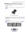
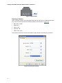
1
Exterity Encoder
AvediaStream e35xx
Administrator’s Guide V1.1
Exterity AvediaStream e35xx Administrator’s Guide V1.1
Notices
Disclaimer
© Exterity Limited 2003-2009
The information contained in this document is
subject to change without notice.
This document contains information that is
protected by copyright. Reproduction,
adaptation, or translation without prior
permission is prohibited, except as under the
copyright laws.
Document Reference
1300-0009-0001
EXTERITY LIMITED MAKES NO WARRANTY
OF ANY KIND WITH REGARD TO THIS
MATERIAL, INCLUDING, BUT NOT LIMITED
TO, THE IMPLIED WARRANTIES OF
MERCHANTABILITY AND FITNESS FOR A
PARTICULAR PURPOSE. Exterity Limited
shall not be liable for errors contained herein or
for incidental or consequential damages in
connection with the furnishing, performance, or
use of this material.
Edition
1.1 Issue 1 (October 2009)
Printed in UK
Exterity Limited
Ridge Way
Hillend Industrial Park
Dalgety Bay,
Fife,
KY11 9JD
Scotland, UK
http://www.exterity.com
Products Covered By This Guide
•
AvediaStream e3520 (avstr-e3520)
•
AvediaStream e3550 (avstr-e3550)
Trademarks
The Exterity building IPTV logo, AvediaStream,
AvediaServer, AvediaCentre, AvediaPlayer,
prodaptor, in-Socket technology, isocket, and
digital simplicity are trademarks or registered
trademarks of Exterity Limited.
Microsoft®, Windows®, and Windows Media
Player® are U.S. registered trademarks of
Microsoft Corporation.
Dolby and the double-D symbol are trademarks
of Dolby Laboratories.
All other trademarks are the property of their
respective owners. All rights reserved.
2
Warranty
A copy of the specific warranty terms applicable
to your Exterity products and replacement parts
can be obtained from Exterity. To request more
information or parts, email
[email protected]
Safety Notices
Before installing and operating these products,
please read the safety information in this
manual.
Exterity AvediaStream e35xx Administrator’s Guide V1.1
Contents
Contents ...................................................................................................................................................... 3
Important Safety Instructions ...................................................................................................................... 7
USA and Canada .............................................................................................................................. 7
EU and Others .................................................................................................................................. 8
Safety Information........................................................................................................................ 8
About this Manual ....................................................................................................................................... 9
Summary........................................................................................................................................... 9
Scope ................................................................................................................................................ 9
Audience ........................................................................................................................................... 9
Associated Documentation ............................................................................................................... 9
Terms and Definitions ..................................................................................................................... 10
How this Manual is Organised ........................................................................................................ 11
1
Getting Started ................................................................................................................................ 12
Connecting the AV Source ............................................................................................................. 12
Connecting an SD Video Source (e3520 only) .......................................................................... 12
Connecting to the Network ............................................................................................................. 12
Connecting to Power ...................................................................................................................... 12
Configuring the IP Address of the Encoder .................................................................................... 12
Naming the Encoder ....................................................................................................................... 12
Configuring Audio/Video Input ........................................................................................................ 13
Configuring Encoding Options ........................................................................................................ 13
Configuring Stream Properties ....................................................................................................... 13
Configuring Channel Announcements ............................................................................................ 13
Checking Status .............................................................................................................................. 13
Checking the operating status of the encoder ........................................................................... 13
Checking the encoder is transmitting data ................................................................................ 13
2
Physical Interfaces .......................................................................................................................... 14
Chassis Interface ............................................................................................................................ 14
3
Exterity AvediaStream e35xx Administrator’s Guide V1.1
Encoder Rear Panel Interface ........................................................................................................ 15
AvediaStream e3520 Interface .................................................................................................. 15
AvediaStream e3550 Interface .................................................................................................. 17
3
Management Interfaces .................................................................................................................. 19
IPTV Manager ................................................................................................................................. 19
Web Management Interface ........................................................................................................... 20
Admin Interface ............................................................................................................................... 21
4
Configuring the Encoder ................................................................................................................. 22
Naming the Encoder ....................................................................................................................... 22
Changing the Admin Password ...................................................................................................... 22
Configuring Network Settings ......................................................................................................... 22
Configuring IP address settings ................................................................................................. 22
Configuring Ethernet Settings .................................................................................................... 23
Configuring Audio/Video Input (e3520 only) ................................................................................... 23
Video format .............................................................................................................................. 23
Frame Rate ................................................................................................................................ 23
Audio input ................................................................................................................................. 24
Configuring Audio/Video Input (e3550 only) ................................................................................... 24
Frame Rate ................................................................................................................................ 24
Audio input ................................................................................................................................. 24
SDI audio group ......................................................................................................................... 24
SDI audio channel ..................................................................................................................... 24
SDI loop-through........................................................................................................................ 25
Configuring Stream Properties ....................................................................................................... 25
Specifying the transport protocol ............................................................................................... 25
Changing the destination address ............................................................................................. 25
Port ............................................................................................................................................ 26
IP TTL ........................................................................................................................................ 26
IP TOS ....................................................................................................................................... 26
Stream on boot .......................................................................................................................... 26
IGMP join group ......................................................................................................................... 26
Stream null packets ................................................................................................................... 27
Stream control ........................................................................................................................... 27
Configuring Encoding Options ........................................................................................................ 27
Configuring video encoding ....................................................................................................... 27
Configuring audio encoding ....................................................................................................... 28
Configuring Channel Announcements ............................................................................................ 28
Turning on/off channel announcements .................................................................................... 28
Specifying the channel name .................................................................................................... 28
Specifying the channel number ................................................................................................. 29
4
Exterity AvediaStream e35xx Administrator’s Guide V1.1
Configuring groups .................................................................................................................... 29
Configuring Remote Device Control ............................................................................................... 29
Infra-red control of AV Source ................................................................................................... 29
Downloading an IR configuration file ......................................................................................... 30
Configuring the master IR client ................................................................................................ 30
Maintenance Tasks ......................................................................................................................... 31
Setting the TFTP server............................................................................................................. 31
Specifying a time server ............................................................................................................ 31
Restarting the encoder .............................................................................................................. 31
Upgrading the encoder firmware ............................................................................................... 31
Restoring the encoder to factory default settings ...................................................................... 32
Exporting/importing configuration settings................................................................................. 32
Logging ........................................................................................................................................... 33
Viewing the local log file ............................................................................................................ 33
Configuring remote logging ....................................................................................................... 33
5
Configuring the Encoder using the Admin Interface ....................................................................... 34
Using the Admin Interface .............................................................................................................. 34
6
Status Monitoring ............................................................................................................................ 36
Viewing Encoder Details ................................................................................................................. 36
Software Version ....................................................................................................................... 36
Description ................................................................................................................................. 36
Serial Number ............................................................................................................................ 36
IP Address ................................................................................................................................. 37
Product Type ............................................................................................................................. 37
Daughtercard ............................................................................................................................. 37
Uptime ....................................................................................................................................... 37
Board Temperature.................................................................................................................... 37
Viewing Operating Status ............................................................................................................... 37
Stream ....................................................................................................................................... 38
Audio/Video Input (e3520 only) ................................................................................................. 38
Audio/Video Input (e3550 only) ................................................................................................. 38
Actual Video Rate ...................................................................................................................... 39
Stream Destination .................................................................................................................... 39
Stream Channel Name .............................................................................................................. 39
Stream Channel Number ........................................................................................................... 39
Viewing Network Statistics.............................................................................................................. 40
7
Troubleshooting .............................................................................................................................. 41
APPENDIX A
Serial Interface Connection ........................................................................................ 43
Cabling ....................................................................................................................................... 43
Connector Wiring ....................................................................................................................... 43
5
Exterity AvediaStream e35xx Administrator’s Guide V1.1
Opening a Session .................................................................................................................... 44
APPENDIX B
6
Support and Contact Information ............................................................................... 45
Exterity AvediaStream e35xx Administrator’s Guide V1.1
Important Safety Instructions
There are no instructions specifically for service personnel in this document. There are no
user serviceable parts inside any Exterity product. To prevent electric shock or fire hazard, do
not remove cover. Refer service to qualified service personnel.
This chapter contains important safety information. If you are unsure about any of the
information in the section, please contact Exterity.
The lightning flash with arrowhead symbol within an equilateral
triangle, is intended to alert the user to the presence of
uninsulated "dangerous voltage" within the product's enclosure
that may be of sufficient magnitude to constitute a risk of
electric shock to persons.
The exclamation point within an equilateral triangle is intended
to alert the user to the presence of important operating and
maintenance (servicing) instructions in the literature
accompanying the product.
USA and Canada
1.
2.
3.
4.
5.
6.
7.
8.
9.
10.
11.
Read these instructions.
Keep these instructions.
Heed all warnings.
Follow all instructions.
Do not use this apparatus near water.
Clean only with dry cloth.
Do not block any ventilation openings. Install in accordance with the instructions contained
in this manual.
Do not install near any heat sources such as radiators, heat registers, stoves, or other
apparatus (including amplifiers) that produce heat.
Do not defeat the safety purpose of the polarized or grounding-type plug. A polarized plug
has two blades with one wider than the other. A grounding type plug has two blades and a
third grounding prong. The wide blade or the third prong are provided for your safety. If the
provided plug does not fit into your outlet, consult an electrician for replacement of the
obsolete outlet.
Protect the power cord from being walked on or pinched particularly at plugs, convenience
receptacles, and the point where they exit from the apparatus.
Only use attachments/accessories specified by the manufacturer.
7
Exterity AvediaStream e35xx Administrator’s Guide V1.1
12. Use only with the cart, stand, tripod, bracket, or table specified by the manufacturer, or
sold with the apparatus. When a cart is used, use caution when moving the cart/apparatus
combination to avoid injury from tip-over.
13. Unplug this apparatus during lightning storms or when unused for long periods of time.
14. Refer all servicing to qualified service personnel. Servicing is required when the apparatus
has been damaged in any way, such as power-supply cord or plug is damaged, liquid has
been spilled or objects have fallen into the apparatus, the apparatus has been exposed to
rain or moisture, does not operate normally, or has been dropped.
15. Do not expose this apparatus to dripping or splashing and ensure that no objects filled with
liquids, such as vases, are placed on the apparatus.
16. To completely disconnect this apparatus from the AC Mains, disconnect the power supply
cord plug from the AC receptacle.
17. The mains plug of the power supply cord shall remain readily operable.
WARNING: To reduce the risk of fire or electric shock, do not expose this apparatus to rain or
moisture.
EU and Others
Do not proceed beyond a WARNING! notice until you have understood the hazardous
conditions and have taken appropriate steps.
Safety Information
WARNING! There are no user serviceable parts inside any Exterity product. To prevent
electric shock or fire hazard, do not remove cover. Refer service to qualified service personnel.
WARNING! For 230/240 volt operation, be sure to use a harmonised grounded 3 conductor
cord, rated 6 Amp minimum. Use a suitable cord for connection to the equipment and
terminating in an IEC approved plug.
This equipment relies upon a safety earth for operation, ensure that you always use a power
cord with appropriate earth and that the inlet to which is inserted also has the appropriate
earth. If in any doubt about the earth provision in your building consult a qualified electrician
WARNING! Use only the dedicated power supply or cord supplied for your device.
WARNING! The Exterity products use ventilation holes for cooling. None of the ventilation
holes should be blocked. Keep all materials at least 5cm away from all the ventilation holes.
WARNING! Do not expose the product to any rain or moisture.
WARNING! Do not use the product near a naked flame e.g. a candle.
WARNING! The operating conditions of the product should be 0°C-40°C with a Relative
Humidity of 5 – 95%. The product should not be operated outside of these conditions.
There are no user-serviceable parts inside these products. Any servicing, adjustment,
maintenance, or repair must only be performed by service-trained personnel.
8
Exterity AvediaStream e35xx Administrator’s Guide V1.1
About this Manual
Summary
This manual explains how to set up, use and manage the AvediaStream e3520 and
AvediaStream e3550 products, which are commonly referred to as “encoders”. Encoders are
network devices that take a signal from an AV device, for example, a DVD player or set-top
box, and output it as an MPEG transport stream over an IP network.
Scope
This edition of the manual refers to version 1.1.x of the encoder software.
The following products are covered:
•
AvediaStream e3520 (avstr-e3520) (HD PRO Encoder)
•
AvediaStream e3550 (avstr-e3550) (HD SDI Encoder)
Note: The AvediaStream e3520 was previously available using the order codes idapt-hdp
and prdpt-hdp.
Audience
This manual is intended for use by systems integrators or systems administrators who are
installing and setting up Exterity products. The manual assumes that readers are familiar with
installing and configuring network-based products.
Associated Documentation
This manual should be used in conjunction with the AvediaStream Installation Guide.
9
Exterity AvediaStream e35xx Administrator’s Guide V1.1
Terms and Definitions
The following terms and definitions are used in this document:
AC-3 – An audio compression scheme, also known as Dolby Digital.
AES – A standard for carrying digital audio.
Board – The printed circuit board within the unit.
Composite video – A type of analogue video signal where the luminance, chrominance and
sync signals are all carried on a single cable. This is often referred to as CVBS.
DHCP – Dynamic Host Configuration Protocol, a protocol used to allocate IP addresses to
devices on an IP network.
H.264 - A standard for video compression, also known as MPEG-4 Part 10 and MPEG-4 AVC
(Advanced Video Coding).
IGMP – Internet Group Management Protocol, a protocol used to manage multicast traffic on
an IP network.
Input – Physical interface on Exterity equipment that receives Audio/Video from a source.
IP – Internet Protocol, a protocol used for communicating data across a network using the
Internet Protocol Suite, also referred to as TCP/IP.
MPEG – A family of compression methodologies for audio and video.
MPEG Transport Stream - A communications protocol enabling multiplexing of digital audio,
video and data which is specified in MPEG-2 Part 1, Systems (ISO/IEC standard 13818-1).
NTP – Network Time Protocol, a protocol for synchronizing the clocks of computer systems.
RTP - Real-time Transport Protocol, a protocol used to carry real time data on an IP network.
SAP – Session Announcement Protocol, a protocol used to advertise the presence of
multicast sessions on an IP network
SDI - The Serial Digital Interface (SDI) is a high speed serial interface that carries
uncompressed video with the option of embedded audio. It is specified as SMPTE 259M
(270MB/s SD-SDI) and SMPTE 292M (1.485Gbit/s HD-SDI).
Source – A device that can provide an Audio/Video input to the encoder, for example, a DVD
player.
Telnet – Telnet is a network protocol that enables one computer to communicate with another
over an IP network.
TFTP – Trivial File Transfer Protocol, a simple file transfer protocol used on IP networks.
UDP – User Datagram Protocol, a transport protocol in the TCP/IP suite, which provides a
connectionless transport mechanism with low overhead.
Unit – Exterity product, for example, an AvediaStream e35x unit containing a printed circuit
board.
YPbPr – A type of component analogue video signal consisting of a colourless component
(luminance), combined with two colour-carrying components (chrominance). This is commonly
referred to simply as “component”.
10
Exterity AvediaStream e35xx Administrator’s Guide V1.1
How this Manual is Organised
This manual is organised as follows:
Section 1 – Getting Started
This section describes how to get the encoder up
and running.
Section 2 – Physical Interfaces
This section describes how to connect your AV
equipment to the encoder.
Section 3 – Management Interfaces
This section describes the management interfaces
you can use to manage the encoder: the IPTV
Manager, Web Management Interface and admin
interface.
Section 4 – Configuring the Encoder
This section describes how to configure the
encoder using the Web Management Interface
Section 5 – Admin Interface
This section describes how to configure the
encoder using the serial Admin Interface.
Section 6 – Status Monitoring
This section explains how to check the operating
status of the encoder.
Section 7 – Troubleshooting
This section provides troubleshooting information if
you are having problems with the encoder.
11
Exterity AvediaStream e35xx Administrator’s Guide V1.1
1 Getting Started
There are certain procedures you need to perform in order to get the AvediaStream e35xx
range of encoders up and running. These procedures are described in this section.
Connecting the AV Source
Before the encoder can stream audio/video on the network, an AV source must be connected.
See Physical Interfaces on page 14 for details on how to connect your AV equipment to the
encoder.
Connecting an SD Video Source (e3520 only)
If connecting an SD video source, it is necessary to configure the type of video being input to
the encoder.
For more information, see Configuring Audio/Video Input (e3520 only) on page 23.
Connecting to the Network
Connect the encoder to the network.
For more information, see the AvediaStream Installation Guide.
Connecting to Power
Connect the encoder to a power source.
For more information, see the AvediaStream Installation Guide.
Configuring the IP Address of the Encoder
By default, the encoder requires a DHCP Server to be available on the network to assign it an
IP address.
There are two methods of assigning a static IP address to the encoder, if required:
•
Temporarily set up a DHCP server on an isolated network. Once an IP address is
assigned to the encoder, you can configure a static IP address using the Web
Management Interface.
For more information, see Configuring Network Settings on page 22.
•
Use the Admin Interface to configure the IP address.
For more information, see Configuring the Encoder using the Admin Interface on page
34.
Allocating a static IP address for the encoder allows continued operation without a DHCP
Server.
For more information, see Configuring Network Settings on page 22.
Naming the Encoder
Provide a name for the encoder so you can easily identify it in the future. This can be done
using the Web Management Interface (see Naming the Encoder on page 22) or the IPTV
Manager (see IPTV Manager on page 19).
12
Exterity AvediaStream e35xx Administrator’s Guide V1.1
Configuring Audio/Video Input
Now configure the Audio/Video input.
For more information, see Configuring Audio/Video Input (e3520 only) on page 23 or
Configuring Audio/Video Input (e3550 only) on page 24.
Configuring Encoding Options
The device starts encoding automatically when an appropriate source is connected. Some
aspects of the encoding can be configured if required.
For more information, see Configuring Encoding Options on page 27.
Configuring Stream Properties
The encoder starts streaming (transmitting an MPEG transport stream on the IP network)
automatically when an appropriate source is connected. Some aspects of the stream can be
configured if required.
For more information, see Configuring Stream Properties on page 25.
Configuring Channel Announcements
The encoder uses SAP (Session Announcement Protocol) to announce its stream (channel) to
receiving devices. Included in the announcements are the name of the channel and the
multicast address and port on which the stream is sent.
This is done automatically once the encoder is up and running.
You may wish to configure channel announcements to suit your requirements. For more
information, see Configuring Channel Announcements on page 28.
Checking Status
Checking the operating status of the encoder
You may wish to check the operating status of the encoder.
For more information, see Status Monitoring on page 36.
Checking the encoder is transmitting data
Viewing the network port utilisation is an easy way to check if the encoder is transmitting data
at the rate expected by the streaming settings.
For more information, see Viewing Network Statistics on page 40.
13
Exterity AvediaStream e35xx Administrator’s Guide V1.1
2 Physical Interfaces
An AvediaStream e35xx HD encoder card can operate in one of the following chassis:
•
AvediaStream c1101
•
AvediaStream c1103
•
AvediaStream c1110
The card has AV interfaces on its rear panel, while its edge connector enables it to access
network and admin ports via the chassis front panel.
Warning: Take care not to touch the edge connector as static electricity might damage the
product. Handle by the enclosure only and insert as soon as possible into the chassis.
Chassis Interface
The Encoder module provides the following interfaces over its edge connector to the chassis:
•
Ethernet interface (10/100Mbps)
•
Admin Interface
•
Status LEDs
•
Power supply
The actual physical interfaces can be found on the chassis front panel. Please refer to the
relevant AvediaStream chassis installation guide for further details.
Pattern (approx rate)
Description
Twice a Second
Running Power on Self Tests
Solid On
Booting operating System, takes approximately 1020 seconds
Once a second
Heartbeat indicates unit is running normally
Alternatively < 1 sec, > 10 secs
Upgrading
Table 1 Heartbeat LED Patterns
14
Exterity AvediaStream e35xx Administrator’s Guide V1.1
Encoder Rear Panel Interface
The AvediaStream e3520 and AvediaStream e3550 have the following functionality:
Name
AvediaStream
e3520
Video Inputs
•
Composite
•
Balanced
•
Component
•
Unbalanced
•
AES digital
•
Embedded SDI
stereo
•
AES digital
(HD PRO)
AvediaStream
e3550
(HD SDI)
Audio Inputs
•
HD-SDI
•
SD-SDI
IR Out Socket
Yes
No
Table 2 Encoder Rear Panel Interface
AvediaStream e3520 Interface
The encoder provides video and audio inputs as follows, as illustrated in Figure 1 below.
Figure 1 AvediaStream e3520 Encoder Rear Panel
Video Inputs
The three BNC connectors for video input support:
•
Composite (Connect the composite signal to the Y input)
•
Component (Connect the Y signal to the Y input, the Pb/U signal to the Pb input and the
Pr/V signal to the Pr input)
15
Exterity AvediaStream e35xx Administrator’s Guide V1.1
The following resolutions and frame rates are supported:
•
525i 59.94Hz
•
625i 50Hz
•
720p 50Hz/59.94Hz/60Hz
•
1080i 50Hz/59.94Hz/60hz
Note: 24Hz is not supported on the e3520 encoder.
Audio Inputs
The two 6.35mm jack sockets for audio input support:
•
Unbalanced audio (Connect mono or stereo audio to the Left/Stereo input via an adaptor
such as the one shown in Figure 2)
•
Balanced audio (Connect to both left and right inputs. Use adaptors such as the one
shown in Figure 3, if necessary).
•
AES digital audio (Connect AES audio to the Right/Digital input via an adaptor such as the
one shown in Figure 3). The AES audio format can be uncompressed (PCM 48kHz) or
compressed (AC-3).
Figure 2 Unbalanced audio adaptor
Figure 3 Balanced audio/AES audio adaptor
IR Out Socket
This is intended to control the attached AV device. The associated IR transmitter is provided
with the unit.
16
Exterity AvediaStream e35xx Administrator’s Guide V1.1
AvediaStream e3550 Interface
The encoder provides video and audio inputs as follows, as illustrated in Figure 4 below.
Figure 4 AvediaStream e3550 Encoder Rear Panel
SDI Interface (IN)
The SDI interface supports SMPTE 259M (270MB/s SD-SDI) and SMPTE 292M (1.485Gbit/s
HD-SDI). Connect an SD-SDI or HD-SDI input using a BNC connector.
The following resolutions and frame rates are supported:
•
525i 59.94Hz
•
625i 50Hz
•
720p 50Hz/59.94Hz/60Hz
•
1080i 50Hz/59.94Hz/60hz
•
1080p 23.98Hz/24Hz
LEDs
The LEDs provide status on the SDI input as follows:
•
Green: an SDI input has been detected.
•
Red: data errors have been detected on the SDI input.
SDI Interface (OUT)
The SDI (OUT) interface is a loop-through interface to enable you to connect the same SDI
input to another device.
Connect using a BNC connector.
17
Exterity AvediaStream e35xx Administrator’s Guide V1.1
This output is disabled by default, and can be configured via the web interface “Input” page.
Warning! Do not connect the output interface to any other output interface as this may
damage the unit.
Audio Inputs
•
Embedded SDI stereo audio (stereo pair selectable from one of 8 pairs embedded within
the SDI video stream)
•
Single female XLR for AES digital audio (PCM 48kHz or compressed AC-3)
This allows the user to encode audio from the SDI interface or to use the AES interface as the
audio source.
Note: The BNC interface is marked with ASI/SDI as this interface is common to the SDI
Encoder and ASI Gateway. The interface is committed to SDI or ASI in the factory and
cannot have its function changed in the field.
18
Exterity AvediaStream e35xx Administrator’s Guide V1.1
3 Management Interfaces
The encoder has three management interfaces, as follows:
•
IPTV Manager
•
Web Management Interface
•
Admin Interface
Note: Each encoding module in a chassis is required to be configured independently.
IPTV Manager
The IPTV Manager is a Windows application that discovers Exterity devices on the network
and uses SNMP to manage a subset of device functionality. It can also be used to start the
encoder’s Web Management Interface, as shown in Figure 5 below.
Note: You can also use a third-party SNMP tool to manage the encoder. Contact Exterity
to obtain the Management Information Base (MIB).
For more information on using the IPTV Manager, see the Exterity IPTV Manager
Administrator’s Guide.
Figure 5 Exterity IPTV Manager
19
Exterity AvediaStream e35xx Administrator’s Guide V1.1
Web Management Interface
You can manage every aspect of the encoder’s functionality using the Web Management
Interface.
The Web Management Interface supports the following web browsers: Microsoft Internet
Explorer and Mozilla Firefox.
You can display the Web Management Interface using the IPTV Manager, as shown in IPTV
Manager on page 19, or by typing the IP address of the encoder directly into your browser.
Open the Web Management Interface as follows:
1. When prompted, enter the correct username and password. The default login details are:
Username: admin
Password: labrador
Note: The administrator can change the admin password using the Web Management
Interface. For more information, see Configuring the Encoder using the Admin Interface
on page 34.
2. The Web Management Interface opens in your browser, as shown below in Figure 6:
Figure 6 Web Management Interface displaying an AvediaStream e3520 encoder
3. Click on the encoder name in the purple bar on the left-hand side to display the menu. In
the above example, it is Encoder00002E.
4. Navigate through the pages, changing settings as appropriate.
5. Click Apply on each page to save your changes.
20
Exterity AvediaStream e35xx Administrator’s Guide V1.1
Note: For more information on how to use the Web Management Interface to configure the
encoder, see Configuring the Encoder on page 22.
Admin Interface
In certain circumstances it may not be possible to manage an encoder via the Web
Management Interface. For these situations, a text-based Admin Interface is provided, which is
available via the serial interface (marked ‘admin’ on the chassis front panel) or via telnet.
For more information on how to use the Admin Interface, see Configuring the Encoder using
the Admin Interface on page 34.
21
Exterity AvediaStream e35xx Administrator’s Guide V1.1
4 Configuring the Encoder
This section of the manual describes how to manage the encoder using the Web Management
Interface (see Web Management Interface on page 20).
Note: When making changes using the Web Management Interface, click Apply to save
your changes on each tab before moving to another tab, otherwise your changes will be
lost.
Naming the Encoder
The encoder can be assigned a name and location. This name can be used to identify the
encoder within the IPTV Manager, while the location you specify is used by the IPTV Manager
to organise devices, such as encoders, into folders. For example, if you specify Group 1, the
encoder appears in Location\Group 1 in the IPTV Manager.
To specify the name and location:
1. Click on the General page
2. Enter the name and location as appropriate
3. Click Apply
Note: The name and location can also be configured using the Properties page in IPTV
Manager.
Changing the Admin Password
By default, a username/password pair of admin/labrador is required to gain access to the
Web Management Interface and the Admin Interface. The admin password can be changed by
the administrator, as required.
To change the admin password:
1. Click on the Authentication tab
2. Enter the desired password in both Password boxes
3. Click Apply
Configuring Network Settings
Configuring IP address settings
You can configure the encoder to obtain an IP address automatically using DHCP, or you can
specify static addressing information, such as IP address, subnet mask and default gateway.
Note: Changes to IP addressing take place immediately on clicking Apply.
To configure the device to be allocated an IP address automatically:
1. Click on the Network tab
2. Click Obtain an IP Address automatically
3. Click Apply
22
Exterity AvediaStream e35xx Administrator’s Guide V1.1
To configure a static IP address:
1.
2.
3.
4.
Click on the Network tab
Click Use the properties below
Specify values for IP Address, Subnet Mask, Default Gateway, DNS
Click Apply
Configuring Ethernet Settings
The encoder’s Ethernet interface is a 10/100 port with auto-negotiation enabled by default. It is
possible to disable auto-negotiation and run the interface with fixed settings of 100Mbps full
duplex (100FD).
Note: In order to avoid Ethernet errors, ensure that the encoder’s interface settings match
the settings for the network switch port the encoder is connected to. This means that both
devices should be configured for auto-negotiation, or both devices should be configured for
a fixed setting of 100FD.
To enable/disable auto-negotiation:
1. Click on the Network tab
2. Choose an option from the Auto-negotiation drop-down box
3. Click Apply
Configuring Audio/Video Input (e3520 only)
Video format
If connecting an HD video source, there is no configuration necessary.
If connecting an SD video source, it is necessary to configure the type of video being input to
the encoder. Valid options are Composite and Component, with the default setting being
Composite. For SD, ensure that the video source is configured in 4:3 mode.
To specify the SD video format:
1. Click on the Input tab
2. Choose an option from the SD Video Format box
3. Click Apply
Frame Rate
The e3520 can handle sources with frame rates of 50Hz, 59.94Hz and 60Hz.
A frame rate of 50Hz is detected automatically and no configuration is required. However, the
encoder cannot automatically distinguish between 59.94Hz and 60Hz, therefore the frame rate
must be configured by the administrator if such a source is connected. The default setting is
59.94Hz.
To specify frame rate:
1. Click on the Input tab
2. Choose an option from the 24/60Hz Frame Rate box
3. Click Apply
23
Exterity AvediaStream e35xx Administrator’s Guide V1.1
Audio input
There are three options available when connecting audio to the encoder: Balanced,
Unbalanced and AES. The default setting is Unbalanced. See AvediaStream e3520
Interface on page 15 for details on audio connections.
To specify the audio input:
1. Click on the Input tab
2. Choose an option from the Audio Input box
3. Click Apply
Configuring Audio/Video Input (e3550 only)
Frame Rate
The e3550 can handle sources with frame rates of 50Hz, 59.94Hz, 60Hz, 23.98Hz and 24Hz.
Usually the encoder will automatically detect the frame rate and no configuration is required.
However, under certain circumstances the encoder may not be able to distinguish between
59.94Hz and 60Hz or between 23.98Hz and 24Hz. In this situation the frame rate can be
configured by the administrator. The default setting is Automatic.
To specify frame rate:
1. Click on the Input tab
2. Choose an option from the 24/60Hz Frame Rate box
3. Click Apply
Audio input
There are three options available when connecting audio to the encoder: AES, Embedded and
Embedded AC-3. The default setting is Embedded. See AvediaStream e3550 Interface on
page 17 for details on audio connections.
To specify the audio input:
1. Click on the Input tab
2. Choose an option from the Audio Input box
3. Click Apply
SDI audio group
When using embedded audio, select from one of four possible groups.
To specify the audio group:
1. Click on the Input tab
2. Choose an option from the Audio Group box
3. Click Apply
SDI audio channel
When using embedded audio, within one group there are four channels. It is possible to select
two different pairs, 1&2 or 3&4. These will often be a stereo pair but need not be.
To specify the audio channel:
1. Click on the Input tab
2. Choose an option from the Audio Channel box
3. Click Apply
24
Exterity AvediaStream e35xx Administrator’s Guide V1.1
SDI loop-through
There are two options available when connecting the encoder to another device: Loopthrough, connecting using a direct wire connection, and Re-clocked loop-through,
connecting using a re-timed connection. The default setting is Disabled.
To specify the SDI loop-through:
1. Click on the Input tab
2. Choose an option from the SDI Loop-through box
3. Click Apply
Configuring Stream Properties
Specifying the transport protocol
The encoder transmits its stream as an MPEG transport stream carried over UDP or RTP. The
default setting is UDP. RTP can be a useful diagnostic tool as RTP packets carry a sequence
number and this can be used to check whether all packets arrive at a receiving device.
To specify the transport protocol:
1. Click on the Stream tab
2. Choose an option in the Transport Protocol box
3. Click Apply
Changing the destination address
By default, the encoder sends its stream addressed to the automatically selected multicast
address 239.192.x.y, where x and y are the last two digits of the device’s own IP address.
However, you can change the destination address to a unicast or multicast address, as
required.
Note: In order to avoid unnecessary network traffic, please ensure that the encoder is
attached to a multicast-enabled network
To specify automatic address selection:
1. Click on the Stream tab
2. Choose Automatic in the Destination Address Selection box
3. Click Apply
To specify the destination address:
1. Click on the Stream tab
2. Choose Manual in the Destination Address Selection box
3. Enter the multicast or unicast address in the Destination Address field
4. Click Apply
25
Exterity AvediaStream e35xx Administrator’s Guide V1.1
Port
By default, the stream is sent to the UDP port 5000. The port can be altered by the
administrator as desired.
To specify the port:
1. Click on the Stream tab
2. Enter a value in the Destination Port box
3. Click Apply
IP TTL
By default, the stream is transmitted with an IP TTL of 7. The TTL can be set to any value
between 0 and 255 to allow operation across different network topologies.
To specify the IP TTL:
1. Click on the Stream tab
2. Enter a value between 0 and 255 in the IP TTL box
3. Click Apply
IP TOS
By default, the stream is sent with an IP TOS value of 0. The value can be set between 0 and
255, though you should take care to set a value appropriate to your network and if necessary
refer to RFC 2474 when choosing the value to set.
To specify the IP TOS:
1. Click on the Stream tab
2. Enter a value between 0 and 255 in the IP TOS box
3. Click Apply
Stream on boot
When this option is selected, the encoder will automatically start to stream when it starts up
(assuming the AV source is on). Deselect this if you do not want the stream to start
immediately on boot. The default setting is for stream on boot to be enabled.
To specify the stream on boot setting:
1. Click on the Stream tab
2. Check or un-check the Stream On Boot box as required
3. Click Apply
IGMP join group
The encoder by default uses IGMP to join the multicast group for its stream. This can be
essential to prevent flooding on some network switches.
If required, this function can be disabled by deselecting the checkbox.
To specify the IGMP Join Group setting:
1. Click on the Stream tab
2. Check or un-check the Send IGMP Join Group box as required
3. Click Apply
26
Exterity AvediaStream e35xx Administrator’s Guide V1.1
Stream null packets
Null packets can be produced during the encoding process, and allow the generated transport
stream to maintain a strict constant bit-rate. Null packets are used for padding only, and their
contents are ignored by receivers. This option is enabled by default.
To specify the Stream Null Packets setting:
1. Click on the Stream tab
2. Check or un-check the Stream Null Packets box as required
3. Click Apply
Stream control
As discussed above, the encoder will automatically start streaming on start-up if the Stream
On Boot function is enabled. However it is possible to start and stop the stream manually as
required.
You can check the current streaming status on both the Status and Stream pages.
To stop or start the stream:
1. Click on the Stream tab
2. Click the Start or Stop button as required
Configuring Encoding Options
The encoder has a number of encoding options which can be configured for both video and
audio.
Configuring video encoding
The device encodes the analogue video in H.264 format. The video can be encoded at
constant bit rate (CBR) or variable bit rate (VBR). For a CBR stream, the encoding bit rate
can be configured. For VBR, the maximum and average encoding bit rates can be configured.
It is possible that the configured bit rate may not be the bit rate used for the encoding, as the
encoder has minimum and maximum limits based on the resolution of the connected video
source. To see the actual encoding bit rate, look at the Status page.
The default setting is constant bit rate at 20Mbps.
For best picture quality, use constant bit rate with as high an encoding bit rate as possible.
To specify the video bit rate mode:
1. Click on the Encoding tab
2. Choose an option in the Bit Rate Mode box
3. Click Apply
To specify the video bit rate (CBR only):
1. Click on the Encoding tab
2. Choose an option in the Video Bit Rate box
3. Click Apply
To specify the maximum bit rate (VBR only):
1. Click on the Encoding tab
2. Choose an option in the Maximum Video Bit Rate box
3. Click Apply
27
Exterity AvediaStream e35xx Administrator’s Guide V1.1
To specify the average bit rate (VBR only):
1. Click on the Encoding tab
2. Choose an option in the Average Video Bit Rate box
3. Click Apply
Configuring audio encoding
The audio input to the encoder is sampled at 48kHz and encoded as MPEG 1 Layer II. The bit
rate can be set to values from 64kbps to 384kbps. The default setting is 384kbps.
Note: If the audio source is AES compressed (AC-3) or embedded AC-3, the audio bit rate
setting is irrelevant. The audio bit rate is simply the original bit rate of the AC-3 source.
To specify the audio bit rate:
1. Click on the Stream tab
2. Choose an option in the Audio Bit Rate box
3. Click Apply
Configuring Channel Announcements
The encoder uses SAP (Session Announcement Protocol) to announce its stream (channel) to
receiving devices. This occurs every 30 seconds. The information in the announcements
enables client (receiver) devices to attach to the stream. Included in the announcements are
the name of the channel and the multicast address and port on which the stream is sent. SAP
channel announcements are sent to multicast address 239.255.255.255, port 9875.
The following options allow some additional information to be put into the announcements.
Turning on/off channel announcements
This option allows the administrator to turn on/off channel announcements.
To configure the announcement setting:
1. Click on the Announcements tab
2. Check or un-check the Announce using SAP box as appropriate
3. Click Apply
Specifying the channel name
This is the currently configured channel (or encoder) name and is configured in the Channel
Name field on the Announcements page.
The default channel name is unique to each unit.
The format of the channel name is as follows: <Encoder type><last 6 digits of MAC address>
For example, Exterity HD-SDI 021391.
This unique name is also displayed on the Status page, in the ‘Stream Channel Name’ field.
To specify the channel name:
1. Click on the Announcements tab
2. Enter the desired name in the Channel Name box
3. Click Apply
28
Exterity AvediaStream e35xx Administrator’s Guide V1.1
Specifying the channel number
The channel number will be used by Exterity IPTV receivers and PC clients to produce an
ordered list of channels.
To specify the channel number:
1. Click on the Announcements tab
2. Enter a value between 0 and 999 in the Channel Number box
3. Click Apply
Configuring groups
The available channels across a network of Exterity devices can be split into groups e.g.
Sport, Children, Adult, allowing the administrator to configure receiving devices to receive only
a subset of available channels. By default, an encoder announces itself in the all group. Use
the “groups” option to put the encoder into one or more specific groups.
To add the encoder to a group or groups:
1. Click on the Announcements tab
2. Enter a comma separated list of group names e.g. teachers,pupils,administrators in the
Groups box
3. Click Apply
To remove the encoder from every group (i.e. add the device to the all group):
1. Click on the Announcements tab
2. Enter all in the Groups box
3. Click Apply
Configuring Remote Device Control
Note: This feature is not available for AvediaStream e3550.
Infra-red control of AV Source
The encoder has the ability to send infra-red (IR) remote control commands to the attached AV
source. These commands are sent based on commands received over the network from IPTV
Manager or an IPTV receiver. In order to use the infra-red (IR) transmitter to control the AV
source, it is necessary to obtain a configuration file with the remote control codes for that
particular device.
Contact your Systems Integrator or Reseller in order to obtain a configuration file.
This IR functionality is illustrated below. In this example, the remote control handset could be
used to play/pause/stop the DVD player.
29
Exterity AvediaStream e35xx Administrator’s Guide V1.1
Figure 7 IR Control of AV Source
Downloading an IR configuration file
To download an IR configuration file:
1. The device uses TFTP to download new remote control configuration files from a TFTP
server. To update the configuration file, first ensure that the correct TFTP server IP
address is specified in the Maintenance page and that the TFTP server is running.
2. Save the configuration file in the following directory on the TFTP server.
<root>/remotes/<manufacturer>/<type>/<manufacturer>_<type>_<id>.conf
For example:
<root>/remotes/sony/dvd/sony_dvd_1.conf
3. Click on the Remote tab
4. Enter the name of the configuration file in the IR Remote Control Type box
5. Click Apply
The new configuration file is downloaded automatically from the TFTP server.
Configuring the master IR client
By default, any device on the network can send remote control commands to the encoder. To
allow only one device to do this, configure that device as the Master IR Client.
To specify the master IR client:
1. Click on the Remote tab
2. Enter an IP address in the Master IR Client Address box
3. Click Apply
To remove the master IR client:
1. Click on the Remote tab
2. Enter 0.0.0.0 in the Master IR Client Address box
3. Click Apply
30
Exterity AvediaStream e35xx Administrator’s Guide V1.1
Maintenance Tasks
This section describes the following tasks that can be used to maintain the encoder.
Setting the TFTP server
The device uses TFTP to download new firmware releases and remote control configuration
files. For this to operate correctly, the encoder must be configured with the IP address of the
TFTP server on the network.
To specify a TFTP server IP address:
1. Click on the Maintenance tab
2. Enter the IP address of the TFTP server in the TFTP Server box
3. Click Apply
Specifying a time server
The encoder uses NTP to maintain accurate time on the device, using the time server
specified. This is useful when examining the device log file as accurate time information will be
attached to log messages.
If a time server is supplied to the device by the DHCP server, this will be used if the
administrator has not already specified a time server.
To specify a time server:
1. Click on the Maintenance page
2. Enter the IP address or the host name of the time server in the Time Server box
Click Apply
Restarting the encoder
You can restart the encoder at any time.
To restart the encoder:
1. Click on the Maintenance tab
2. Click Reboot Server
Upgrading the encoder firmware
By upgrading the encoder’s firmware regularly, you can ensure that you are always using the
most recent encoder software.
WARNING: Do not switch the encoder off while the upgrade process is running. The
process takes several minutes, during which time the LED flashes alternately slow and fast.
To upgrade the encoder to a new version of firmware:
1. Ensure that the TFTP server is running.
2. Ensure that the hd_encoder_full.srec firmware file (e3520 and e3550) is hosted
correctly in the root directory of the TFTP server.
3. Click on the Maintenance page.
4. Ensure that the TFTP server address is configured correctly (see Setting the TFTP
server on page 31)
5. Ensure that the Firmware filename is configured correctly and matches the name of the
firmware file (by default hd_encoder_full.srec).
6. Click Upgrade Firmware
31
Exterity AvediaStream e35xx Administrator’s Guide V1.1
The firmware is downloaded from the TFTP server and copied to flash. This process will
take several minutes.
Restoring the encoder to factory default settings
You can return the encoder to its factory default configuration.
Note: If you restore the encoder to factory default settings, you will lose all previously
saved settings. You can however restore these if you have saved your configuration, as
described in Exporting/importing configuration settings on page 32.
To restore the encoder factory default settings:
1. Click on the Maintenance tab
2. Click the Return to factory defaults button
Exporting/importing configuration settings
Once you have configured the receiver, you can store your configuration settings in a single
file. You can use the file to restore your settings should you need to. You can also use a saved
configuration to replicate identical settings on multiple devices.
Note: Device naming and IP addressing information is not exported/imported. This means
that a configuration file can be imported to multiple units.
To export configuration settings:
1. Ensure that the TFTP server is running
2. Click on the Maintenance page
3. Ensure that the TFTP Server address is configured correctly (see Setting the TFTP
server on page 31)
4. Enter a name for your configuration archive in the Export filename box
5. Click Export configuration
The configuration file is uploaded to the root directory of the TFTP server.
To import configuration settings:
1. Ensure that the TFTP server is running
2. Click on the Maintenance page
3. Ensure that the TFTP server address is configured correctly (see Setting the TFTP
server on page 31).
4. Enter the name of the configuration archive that you are using in the Import Filename box
5. Click Import configuration
The configuration archive is downloaded from the TFTP server.
32
Exterity AvediaStream e35xx Administrator’s Guide V1.1
Logging
The encoder saves historical information about internal events within the device to its log file.
This can be useful in troubleshooting problems with the device.
Viewing the local log file
All log file information is automatically saved locally.
To view the log file:
1. Click on the Logging page
2. Click the Show log button
The log file is displayed in the browser window.
Configuring remote logging
To save device log information to a remote server, you need to install a syslog server, such as
the Kiwi Enterprises Syslog Daemon.
To configure remote logging:
1. Click on the Logging page
2. Select Local and Remote Logging
3. In Syslog server, enter the IP address or host name of the syslog server where the log
files are to be stored
4. In Syslog port, enter the port number on the syslog server (default value is 514)
5. For Logging level, select an option ranging from 0-Emergency to 7-Debug (0 represents
the least debug information and 7 represents the most)
6. Click Apply
33
Exterity AvediaStream e35xx Administrator’s Guide V1.1
5 Configuring the Encoder using the Admin
Interface
In certain circumstances it may not be possible to manage an encoder via the Web
Management Interface. For these situations, a text-based Admin Interface is provided, which is
available via the serial interface (marked ‘admin’ on the chassis front panel) or via telnet.
See APPENDIX A for details of how to connect to the serial admin port.
Using the Admin Interface
Once connected, log in using the following details:
Username: admin
Password: labrador (default admin password for the Web Management Interface)
When successfully logged in, the Admin Interface Main Page is displayed, as shown below:
Figure 8 Admin Interface Main Page
The following options are provided:
1) Show syslog
This displays the device log file.
2) Show Bootloader params
This page displays the internal configuration used by the bootloader.
3) Show Network Config
This page displays the IP addressing information of the device.
4) Set Network Config
This page allows the administrator to set the IP address of the device.
34
Exterity AvediaStream e35xx Administrator’s Guide V1.1
5) Set Admin Password
Allows the administrator to change the default admin password for the serial and web
interfaces.
6) Run a shell
This allows the administrator to run a shell as admin.
7) Return to factory defaults
This page allows the administrator to set all configuration to factory defaults.
8) Upgrade
This allows the administrator to specify the TFTP server and initiate a firmware upgrade.
9) Reboot
Reboots the device.
9) Exit
Exits the Admin Interface Main Page.
35
Exterity AvediaStream e35xx Administrator’s Guide V1.1
6 Status Monitoring
This section explains how to check the operating status of the encoder.
Viewing Encoder Details
To view details about the encoder, select the General page using the Web Management
Interface.
The General page is displayed, as shown below:
Figure 9 Web Manager Interface General Page
The following information is displayed on the General page:
Software Version
The current software version running on the device.
Description
A unique string identifying this particular software version.
Serial Number
The MAC address of the device.
36
Exterity AvediaStream e35xx Administrator’s Guide V1.1
IP Address
The IP address in use on the device, either configured statically or assigned by DHCP.
Product Type
Identifies the exact type of hardware in use on the unit.
Daughtercard
Indicates which interface type is on this device.
Uptime
The length of time since the last power-on or reboot.
Board Temperature
The temperature of the board in the chassis.
Note: This information is useful for identifying the software and hardware revisions in use in
this module. If contacting technical support regarding a problem with the device, it can be
useful to provide all this information.
Viewing Operating Status
To view details of the operating status of the encoder, select the Status page using the Web
Management Interface.
The Status page is displayed, as shown below:
Figure 10 Web Manager Interface Status Page
37
Exterity AvediaStream e35xx Administrator’s Guide V1.1
The following information is displayed on the Status page:
Stream
Provides information on the status of the stream, as described in the table below:
Status
Description
Started
The unit is currently streaming
Stopped
User has stopped streaming or has not attempted to start streaming.
Waiting for video
source
The encoder has been unable to find a suitable video source. Check the
video cable(s) has/have been correctly attached to the unit and that the
video source is turned on and working.
Unsupported video
format
The AV source has been detected but the video format cannot be encoded.
Table 3 Stream Status
Audio/Video Input (e3520 only)
Audio Input
Displays the currently configured audio input type, as configured on the Input page. This will
be one of:
•
Balanced
•
Unbalanced
•
AES
If using AES audio, the type of audio detected is also specified here. This will be one of:
•
PCM 48000Hz (i.e. uncompressed digital audio. Other sampling rates may be reported but
only 48000Hz is supported)
•
Bitstream (i.e. compressed digital audio. AC-3 is the only type supported)
Video Input
Describes the input video the encoder has configured/detected. Three items are reported here:
•
Format: Component (HD) or Component/Composite (SD), as configured in the Input page
for the detected resolution.
•
Detected resolution: 525i, 625i, 720p or 1080i
•
Detected frame rate: 50Hz, 59.94Hz or 60Hz
See AvediaStream e3520 Interface on page 15 for a list of valid combinations of resolution
and frame rate.
If no video signal is detected, the message “No Signal” will be displayed here.
Audio/Video Input (e3550 only)
Audio Input
This is a textual output indicating the configured audio input and what has been detected.
If the unit is configured for embedded audio, the following information is displayed:
38
•
Configured group (group 1, 2, 3 or 4 as configured on the Input page).
•
Configured channels (channels 1/2 or 3/4 as configured on the Input page).
Exterity AvediaStream e35xx Administrator’s Guide V1.1
•
Lock indicator ([locked] or [no lock] indicates if audio has been detected on the configured
group and channels).
•
Detected groups (any combination of groups 1 – 4) or the message “no audio detected”.
A sample output could be as follows:
Audio Input:
Group 1, chans 1/2 [locked], groups 1,2,3,4 detected
If the unit is configured for AES, the information displayed will be one of the following:
•
PCM 48000Hz (i.e. uncompressed digital audio. Other sampling rates may be reported but
only 48000Hz is supported)
•
Bitstream (i.e. compressed digital audio. AC-3 is the only type supported)
Video Input
Describes the input video the encoder has detected. The items reported here are:
•
SDI standard: SD-SDI or HD-SDI
•
Resolution: 525i, 625i, 720p, 1080i or 1080p
•
Frame rate: 23.98Hz, 24Hz, 50Hz, 59.94Hz or 60Hz
See AvediaStream e3550 Interface on page 17 for a list of valid combinations of resolution
and frame rate.
If no video signal is detected, the message “No Signal” will be displayed here.
Actual Video Rate
Displays the Actual Video Rate, which is determined by the input/source present and the
Video Bit Rate configured on the Encoding page.
The encoder uses a range of video rates, depending on the input/source that is present:
•
SD sources have an allowable range of 2 to 10Mbits/s
•
A 720p source has an allowable range of 4 to 20Mbits/s
•
A 1080i source has an allowable range of 6 to 20Mbits/s
•
A 1080p source has an allowable range of 6 to 20Mbits/s (e3550 only)
For example, if the Video Bit Rate is configured to 20Mbps but an SD source is connected, the
actual video bit rate will be 10 Mbits/s.
Stream Destination
Displays the URI of the stream, including the multicast address and port, as configured on the
Stream page.
Stream Channel Name
Displays the currently configured channel name, as configured on the Announcements page.
Stream Channel Number
Displays the currently configured channel number, as configured on the Announcements
page.
39
Exterity AvediaStream e35xx Administrator’s Guide V1.1
Viewing Network Statistics
Viewing the network port utilisation is an easy way to check if the encoder is transmitting data
at the rate expected by the streaming settings.
To view details of network port utilisation, select the Network page using the Web
Management Interface.
The Network page is displayed, as shown below:
Figure 11 Web Manager Interface Status Page
The Ethernet interface statistics are shown at the bottom of the page. On the Transmit side,
the % Utilisation should approximately match the “Actual Video Rate” specified on the Status
page.
should approximately match:
You would normally expect to see very little traffic on the Receive side.
40
Exterity AvediaStream e35xx Administrator’s Guide V1.1
7 Troubleshooting
Problem
Possible Cause
Solution
Device does not appear in IPTV
Manager
Network connection faulty or
cannot obtain IP address.
Check Ethernet connections or
replace cable.
Check that DHCP Server is
running on network.
Check switch settings match unit
Ethernet settings.
IPTV Manager cannot
communicate with device
Encoder does not appear to be
streaming
Device is definitely streaming
but client cannot connect to
stream
Device is streaming but video
and or audio is broken up on
client
PC has firewall configured,
blocking SNMP traps.
Disable firewall, or configure
firewall to allow UDP port 162
traffic to this application.
PC has another application
listening for SNMP traps.
Close down SNMP trap listener.
Network connection faulty
See above
Device has an IP address on a
different subnet to the
management station
Use a management station
configured with an appropriate
IP address to manage the
device.
Device is upgrading (indicated
by alternately slow and fast LED
flash)
Wait for upgrade to complete
AV source not connected or
powered off.
Check connections and power to
AV source. Check the status
page to see if the encoder thinks
it is attached to a valid video
source
Video input setting wrong (SD
mode).
Check the video input setting
matches the AV input to the
encoder.
The cabling is incorrect e.g. the
Y cable is not attached to the Y
BNC
Check cabling.
Multicast address is not unique
Particularly if the multicast
address was assigned manually,
check it is unique.
Client cannot accept H.264
Update the client software or
use a different client to view the
stream.
If using PC client, PC Firewall is
preventing video traffic
Disable firewall, or configure
firewall to allow traffic to this
application.
Network is not IGMP enabled
Check the configuration of the
network switch(es).
Check the switch(es) for errors
The streaming bit rate exceeds
the capability of the client
Lower the encoding bit rate.
41
Exterity AvediaStream e35xx Administrator’s Guide V1.1
After upgrade, the device is still
running the old version of
firmware.
Board temperature more than 20
degrees centigrade above
ambient temperature
42
The correct firmware file is not
on the TFTP Server.
Put the correct file on the TFTP
Server.
The TFTP Server address
configured for the device is
wrong
Check that the TFTP Server
address is the address of the
machine the TFTP Server is
running on.
The TFTP Server is not running.
Start the TFTP Server.
The TFTP Server is not
configured to send files.
Fix the security settings on the
TFTP Server.
Air vents are blocked.
Check that air vents are not
blocked.
Fans have stopped running.
Check that fans are running.
None of the above.
If the problem persists, switch off
the unit and contact your Exterity
systems integrator or reseller.
Exterity AvediaStream e35xx Administrator’s Guide V1.1
APPENDIX A Serial Interface Connection
The serial admin interface provides the ability to manage a small subset of device functionality
e.g. to configure an IP address.
Cabling
To connect to the serial interface use the DB-9 – RJ45 adaptor supplied by Exterity (shown in
Figure 12.
Figure 12 DB-9 to RJ45 serial adaptor
The female DB-9 connector should be plugged into the serial port on a PC. A straight-through
network cable should be used between the RJ45 socket on the adaptor and the admin port on
the Exterity device.
Note that although the cable fits, the admin port should not be connected to the Ethernet port
on a PC.
Connector Wiring
If you do not have a connector you can make one using the details shown in Figure 13 and
Table 4.
DB9 Pin No
Description
RJ45 Pin No
2
TxD
8
3
RxD
2
5
GND
4
Table 4 Serial Pin Out
Figure 13 DB-9 connector
43
Exterity AvediaStream e35xx Administrator’s Guide V1.1
Figure 14 RJ45 socket
Opening a Session
Open a terminal program such as Hyperterminal (this can be found on a standard Windows
PC). Set up the serial port with the following settings (see example in Figure 15):
•
Baud rate: 115200
•
Data bits: 8
•
Parity: none
•
Stop bits: one
•
Flow control: none
The program should now connect and present a login prompt if the return key is pressed.
Figure 15 Serial port settings
44
Exterity AvediaStream e35xx Administrator’s Guide V1.1
APPENDIX B Support and Contact Information
Technical Support for Exterity products is provided by authorised Systems Integrators and
Resellers. Please contact your Systems Integrator or Reseller with any Support issues.
45