Home
Explore Categories
Baby & children
Computers & electronics
Entertainment & hobby
Fashion & style
Food, beverages & tobacco
Health & beauty
Home
Industrial & lab equipment
Office
Old
Pet care
Sports & recreation
Vehicles & accessories
Top types
Audio & home theatre
Cameras & camcorders
Computer cables
Computer components
Computers
Data input devices
Data storage
Networking
Print & Scan
Projectors
Smart wearables
Software
Telecom & navigation
TVs & monitors
Warranty & support
other →
Top brands
APC
Canon
Conceptronic
IBM
Sony
Targus
other →
Top types
Infotainment
Musical instruments
Video games & consoles
other →
Top brands
other →
Top types
Binding machines
Boards
Calculators
Correction media
Desk accessories & supplies
Drawing supplies
Equipment cleansing kit
Folders, binders & indexes
Laminators
Mail supplies
Paper cutters
Sorters
Storage accessories for office machines
Typewriters
Writing instruments
other →
Top brands
Belkin
Brother
Cables Direct
Canon
Casio
Fujitsu
HP
Kensington
Philips
Sharp
T'nB
Targus
Tripp Lite
Trust
V7
other →
Top types
Bedding & linens
Cleaning & disinfecting
Do-It-Yourself tools
Domestic appliances
Home décor
Home furniture
Home security & automation
Kitchen & houseware accessories
Kitchenware
Lighting
other →
Top brands
Baumatic
Bosch
Cuisinart
DeLonghi
Electrolux
Franke
Hama
Kenwood
KitchenAid
Miele
Panasonic
Philips
Siemens
Smeg
Tristar
other →
Top types
Bags & cases
Children carnival costumes
Clothing care
Clothing hangers
Dry cleaners
Fabric shavers
Men's clothing
Tie holders
Ultrasonic cleaning equipment
Watches
other →
Top brands
Braun
Grundig
Irox
Mitsubishi Electric
Olympia
Omega
Philips
Sencor
SEVERIN
Shark
Solac
Termozeta
Timex
V7
Velleman
other →
Top types
Electrical equipment & supplies
Measuring, testing & control
Personal safety & protection
other →
Top brands
other →
Top types
Blood pressure units
Electric toothbrushes
Epilators
Feminine hygiene products
Foot baths
Hair trimmers & clippers
Makeup & manicure cases
Men's shavers
Personal paper products
Personal scales
Shaver accessories
Skin care
Solariums
Teeth care
Women's shavers
other →
Top brands
AEG
Audiovox
Black & Decker
Bosch
Hama
Honeywell
Kenmore
König
Panasonic
Philips
RCA
Rexel
SEVERIN
Siemens
Zanussi
other →
Top types
Hot beverage supplies
other →
Top brands
other →
Top types
Electric scooters
Motor vehicle accessories & components
Motor vehicle electronics
other →
Top brands
Razer
other →
Top types
Baby bathing & potting
Baby furniture
Baby safety
Baby sleeping & bedding
Baby travel
Feeding, diapering & nursing
Toys & accessories
other →
Top brands
other →
Top types
Bicycles & accessories
Bubble machines
Camping, tourism & outdoor
Fitness, gymnastics & weight training
Martial arts equipment
Skateboarding & skating
Smoke machines
Sport protective gear
Target & table games
Water sports equipment
Winter sports equipment
other →
Top brands
Chauvet
CHAUVET DJ
HQ Power
PROEL
other →
Top types
Pet hair clippers
other →
Top brands
Andis
other →
Top types
Baby Care
Computer equipment
Gadgets
Games
Home audio
Household appliances
Kitchen appliances
Lawn and Garden
Marine
Musical equipment
Personal care
Photography and Optics
Power tools
Sport & travel
Video and TV accessories
other →
Top brands
Acer
Asus
Canon
Cisco
Craftsman
Emerson
Epson
Makita
Miele
Motorola
Samsung
Sharp
Siemens
Whirlpool
Yamaha
other →
Upload
No category
Download
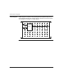
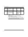
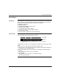
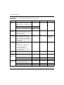
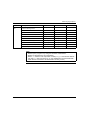
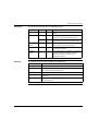
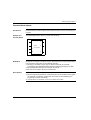
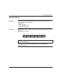
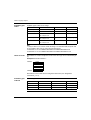
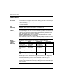
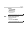
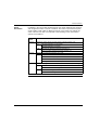
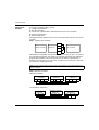
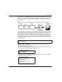
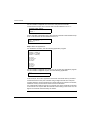
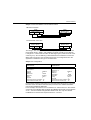
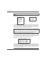
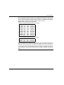
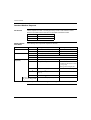
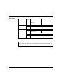
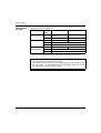
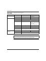
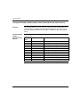
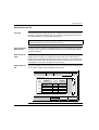
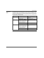
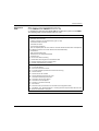
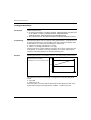
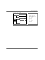
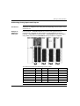
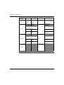
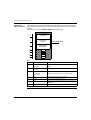
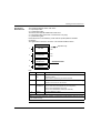
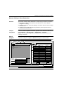
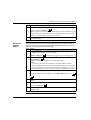
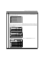
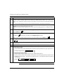
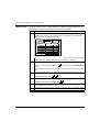
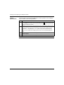
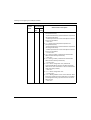
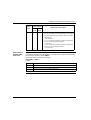
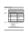
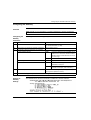
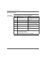
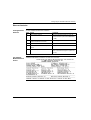
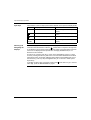
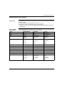
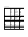
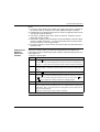
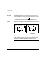
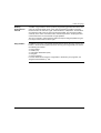
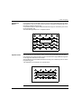
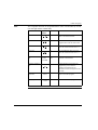
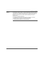
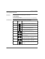
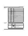
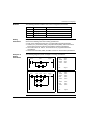
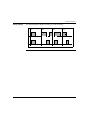
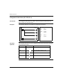
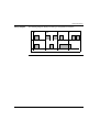
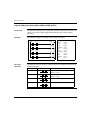
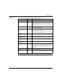
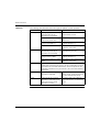
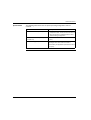
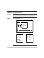
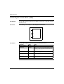
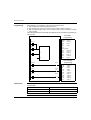
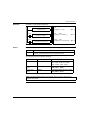
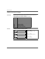
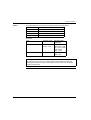
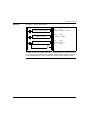
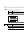
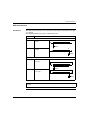
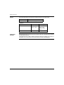
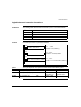
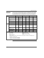
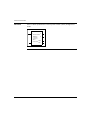
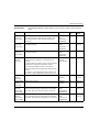
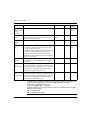
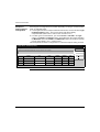
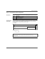
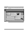
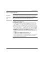
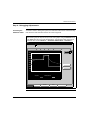
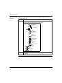
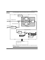
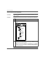
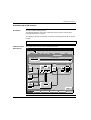
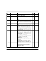
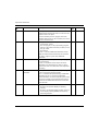
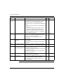
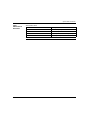
Twido programmable controllers
1
2
3
4
5
6
7
8
9
10
11
12
13
14
15
16
17
18
19
20
21
22
23
24
25
26
27
28
29
30
31
32
33
34
35
36
37
38
39
40
41
42
43
44
45
46
47
48
49
50
51
52
53
54
55
56
57
58
59
60
61
62
63
64
65
66
67
68
69
70
71
72
73
74
75
76
77
78
79
80
81
82
83
84
85
86
87
88
89
90
91
92
93
94
95
96
97
98
99
100
101
102
103
104
105
106
107
108
109
110
111
112
113
114
115
116
117
118
119
120
121
122
123
124
125
126
127
128
129
130
131
132
133
134
135
136
137
138
139
140
141
142
143
144
145
146
147
148
149
150
151
152
153
154
155
156
157
158
159
160
161
162
163
164
165
166
167
168
169
170
171
172
173
174
175
176
177
178
179
180
181
182
183
184
185
186
187
188
189
190
191
192
193
194
195
196
197
198
199
200
201
202
203
204
205
206
207
208
209
210
211
212
213
214
215
216
217
218
219
220
221
222
223
224
225
226
227
228
229
230
231
232
233
234
235
236
237
238
239
240
241
242
243
244
245
246
247
248
249
250
251
252
253
254
255
256
257
258
259
260
261
262
263
264
265
266
267
268
269
270
271
272
273
274
275
276
277
278
279
280
281
282
283
284
285
286
287
288
289
290
291
292
293
294
295
296
297
298
299
300
301
302
303
304
305
306
307
308
309
310
311
312
313
314
315
316
317
318
319
320
321
322
323
324
325
326
327
328
329
330
331
332
333
334
335
336
337
338
339
340
341
342
343
344
345
346
347
348
349
350
351
352
353
354
355
356
357
358
359
360
361
362
363
364
365
366
367
368
369
370
371
372
373
374
375
376
377
378
379
380
381
382
383
384
385
386
387
388
389
390
391
392
393
394
395
396
397
398
399
400
401
402
403
404
405
406
407
408
409
410
411
412
413
414
415
416
417
418
419
420
421
422
423
424
425
426
427
428
429
430
431
432
433
434
435
436
437
438
439
440
441
442
443
444
445
446
447
448
449
450
451
452
453
454
455
456
457
458
459
460
461
462
463
464
465
466
467
468
469
470
471
472
473
474
475
476
477
478
479
480
481
482
483
484
485
486
487
488
489
490
491
492
493
494
495
496
497
498
499
500
501
502
503
504
505
506
507
508
509
510
511
512
513
514
515
516
517
518
519
520
521
522
523
524
525
526
527
528
529
530
531
532
533
534
535
536
537
538
539
540
541
542
543
544
545
546
547
548
549
550
551
552
553
554
555
556
557
558
559
560
561
562
563
564
565
566
567
568
569
570
571
572
573
574
575
576
577
578
579
580
581
582
583
584
585
586
587
588
589
590
591
592
593
594
595
596
597
598
599
600
601
602
603
604
605
606
607
608
609
610
611
612
613
614
615
616
617
618
619
620
621
622
623
624
625
626
627
628
629
630
631
632
633
634
635
636
Transcript
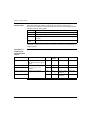
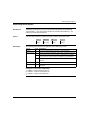
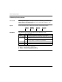
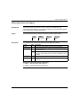
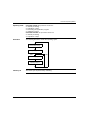
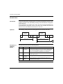
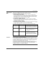
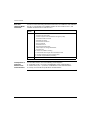
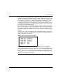
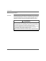
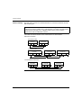
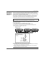
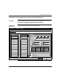
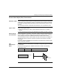
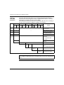
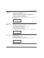
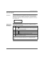
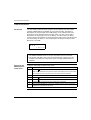
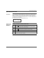
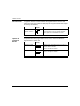
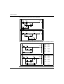
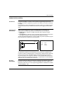
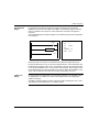
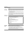
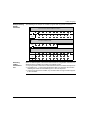
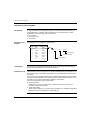
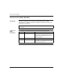
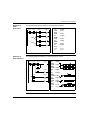
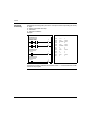
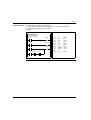
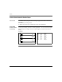
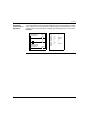
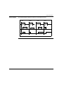
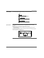
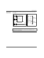
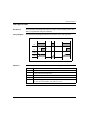
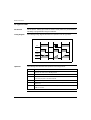
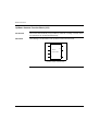
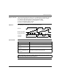
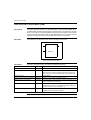
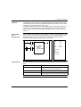
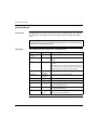
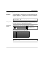
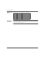
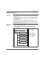
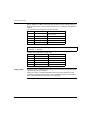
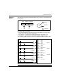
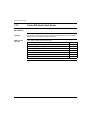
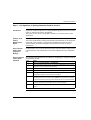
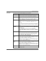
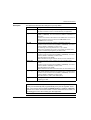
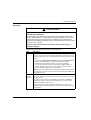
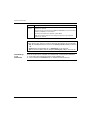
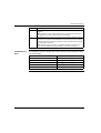
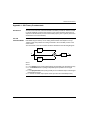
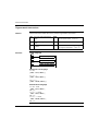
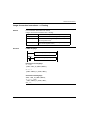
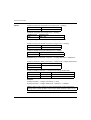
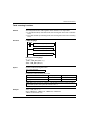
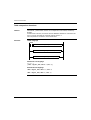
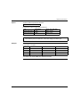
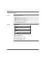
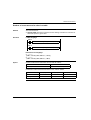
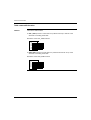
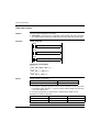
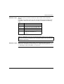
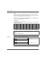
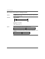
Ladder Language
342
TWD USE 10AE
Related documents
Twido Soft - Elmatik AS
Automates programmables Twido - Site de l`académie de Grenoble
Automates programmables Twido
Twido Automates programmables - Maintenance
Automates programmables Twido
TwidoSuite V1.2
3 - Schneider Electric
Descargar (PDF, 4.73 Mb, abre una nueva - schneider
Twido installazione
Automates programmables Twido
Controlador programable Twido
Cisco Systems 10200 User's Manual