1
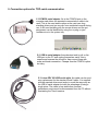
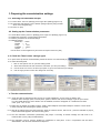
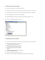
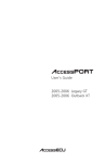
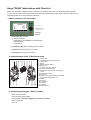
Using TPS400 Total stations with TheoLt r4
NOTE: This document is additional to the TheoLt r4.5 User Manual and TheoLt r4.5 Quick Start Guide supplied
it covers the use of the Leica TPS 400 series instrument. This information should be used in conjuction with the Leica
supplied manuals for the TPS 400 series instrument.
1. Basic controls on the instrument
The Function key accesses
• Screen back-light,
• EDM settings : RL/IR(Reflector-Less/Infra-Red)
• Laser plummet,
• Laser pointer.
The Navigation key allows scrolling of screen options.
The Enter key confirms entry of user values.
The Esc key returns to previous screen.
2. Important parts of the TCR 400 instrument
1)
2)
3)
4)
5)
6)
7)
8)
9)
10)
11)
12)
13)
14)
15)
16)
17)
18)
Optical sight
Integrated guide light EGL (optional)
Vertical drive
Battery
Battery stand for GEB111
Battery cover
Eyepiece; focussing graticule
Focussing telescope image
Detachable carrying handle with mounting
screws
Serial interface RS232
Foot screw
Objective with integrated Electronic Distance
Measurement (EDM); Beam exit
Display
Keyboard
Circular level
On/Off key
Trigger key
Horizontal drive
TC400Z2
3. Customising the trigger "banana" button
Select the menu screen
At the first page select settings
The first option is Contrast, Trigger Key, User key, V- setting
Select Trigger Key
Set to All
4. Setting up the instrument for measurement
3. Place the instrument carefully on
the tripod. Check the tripod is stable,
the stage roughly level and the
plummet is over the point.
2.
1.Take
the tripod, keep its legs
together and loosen the clamping
screws, let the legs drop out as
you pull the stage up to your chin
and re-tighten the clamping
screws.
Spread the legs open to form a stable
shape. Place the feet so that they won’t slip.
Place the tripod approximately over the point,
placing your foot over the point and moving the
tripod over your foot can help. Sight the point
on the ground through the hole in the tripod
stage and moving the whole assembly by
rotation of 2 feet about the 3rd, line the centre
of the stage up with the point.
5.
4. Secure the instrument tribrach to the
tripod with the central fixing screw. The
screw should be tightened firmly.
Once close to the point fine
adjustment is done with the tribrach
foot-screws. Use 2 of the foot screws by
turning your thumbs out or in together
[but never turning them in the same
direction] to move the plummet onto the
rd
point. The 3 screw will provide the
motion to move at right angles to the first
movement.
6. With the plummet centred on
the point the instrument is now
levelled by adjustment of the tripod
legs. Working on each leg in turn
slacken off the clamping screw and
slide the leg to bring the instrument
bubble in line with its centre circle.
Re-tighten the clamping screw
securely before adjusting the next.
5. Connection options for TCR serial communication.
5.1 PCMCIA serial adapter: fits in the PCMCIA port on the
computer and allows the standard communication cable to be
used. This is the most stable option as the card uses long
standing drivers and can recover from accidental removal during
use. It will need installing with the correct drivers and the pot
assignment can be identified by using the un-plug or eject
hardware icon in the system tray.
5.2. USB to serial adapter: these devices tend to pull on the
USB port on the PC and unplug themselves easily: this is
unwelcome because the drivers for them cannot cope with
make and break connection. Cheaper than the PCMCIA option
but risky.
5.3. Leica GEV 189 USB serial cable: this cable can be used
as a replacement for the standard Dsub 9 cable. It is supplied
with the required drivers and works in much the same way as
the USB to serial adapter but with the advantage of being a
single piece. The cable is less stable than its serial
predecessor and cannot be disconnected from the PC without
terminating the TheoLt session.
6. Preparing the comminication settings
6.1. Selecting the RS232 data out put
6.1.1 Press ‘Menu’, then ‘F2’ (Settings), then ‘Page’ twice (Settings page 3 of 4)
6.1.2 Check that ‘Data Output’ is set to ‘RS232’ (change option by using the side
arrow on the navigation key)
6.1.3 Press ‘F4’ (OK)
6.2. Setting up the Communication perameters
6.2.1 At the Menu screen, press ‘F2’ (Settings), then 'Page' once (Settings page 2 of 4)
6.2.2 Select the 2nd option: 'Communication Perameters'
6.2.3 Set the perameters to the default settings.
6.2.4 Default settings
Baud-rate = 19200
Databit
=
8
Parity
=
none
Endmark =
CR/LF
Stopbit
= 1
Use the arrow on the navigation key and 'enter' as required. Press ‘F4’ (OK)
6.3. Check the TheoLt coms settings agree
6.3.1 Open TheoLt (if there is no authorisation present see TheoLt r4.5 User Manual p5)
6.3.2 Select the settings tab:
I. Click on the spanner icon to open the settings panel.
II. Select the instrument tab and choose the instrument. port and port settings
III. Use the 'dots' icon next to the Serial port option to get to the instrument port settings
IV.
Use the 'apply' button to enter the changes at each step
6.4. Test the communication
6.4.1 Check the cable is attached and the com port is correctly identified: if you are using an adaptor open
Windows device manager (Start, conntrol panel, system, hardware tab, device manager) to get the port number.
For Leica USB cables the correct drivers must be installed, the device will appear as a USB download cable
under ports: com & LPT.
6.4.2 Make sure the adaptor is installed correctly: USB to serial adaptors and PCMCIA adaptors need the correct drivers
to work, some will need re-booting the system on install.
6.4.3 With all the settings done level the instrument, select the measure screen, switch to RL, press the indicated all (F3) key
and the data should appear in the TheoLt history panel.
6.4.4 The first instrument meaurement (observation) will prompt a recording to RS232 message this will need to be
confirmed with a yes by using the indicated key.
6.4.5 The instrument must be correctly levelled for measuremet to take place, it has a compensator that will detect
dislevelement and cancel the measurement sequence.
6.5. TTrouble shooting coms settings
6.5.1 Use the device manager to confirm the port number in use
6.5.2 Make sure the USB device is only disconnected at the instrument end during a TheoLt session
6.5.3 Remember TheoLt will need to be re-started If changes are made to the instrument settings.
6.5.4 Com port adaptors will need the correct drivers installed
6.5.5 PCMCIA and USB devices need to be removed using the un plug or eject hardware tool.
6.5.6 TheoLt can only adress com ports up to Com 8
6.6. Getting the data into AutoCAD
6.6.1 Use the TheoLt settings panel to set up the link to AutoCAD (see p 8 TheiLt r4 User Manual)
.
6.6.2 Make sure the USB device is only disconnected
at the instrument end during a session.
6.6.3 Remember TheoLt will need to be re-started If
changes are made to the instrument settings.
6.6.4 Com port adaptors will need the correct drivers
installed
6.6.5 PCMCIA and USB devices need to be removed using
the un-plug or eject hardware tool.
6.6.6 TheoLt can only adress com ports up to Com 8
6.6.7 Remember to use an AutoCAD commanmd (line) to capture the data in your drawing!
6.7. Using the Leica USB cable GEV 189
6.7.1.Unlike the old serial Dsub9 com port the Universal Serial Bus port
allocation procedure for serial devices requires drivers.
If you have acess to the Windows hardware device manager the port number can be
determined.
6.7.2.Like most USB serial devices the cable will need drivers installed for each
USB port you intend to use it on: you cannot assume because you have
installed the drivers once they will work on the next port you use. Make
sure you have the drivers CD supplied in a drive on your system before
you plug the cable in for the first time. Windows will run the new hardware
found response when the cable is plugged in. You will need to restart the
system after installing the drivers.
6.7.3.TheoLt only has port allocations from Com 1 to 8 do not attempt to install
the cable unless you are confident you can assign a port address in this range
6.7.4.Unsafe make and break connection. A feature of USB serial cables is the
poor stability on reconnection. If you pull the USB connector out of the
computer it will end serial communication for the TheoLt session. If you replace the cable in
the same USB port TheoLt will find it on re-start, if you plug it back into the
wrong port you will need to go to the TheoLt settings and find the new
comport number. If you don’t know the comport number then the only way
to find it is via the Hardware Device Manager.
6.7.5.Safe make and break: if you need to break the connection (to move the
instrument etc.) it is essential to unplug at the Lemo end not the USB end:
the Lemo connector can be plugged in and out of its port happily: the USB
cannot!
Lemo
The Lemo can be un-plugged from
Dsub9
the instrument, as can the old
Dsub9 connector: the USB must
never be disconnected unless the
comms session is over.
USB
6.8 Reassigning the port number on the PC
Open the ‘Ports’ tree
to see your port
allocations
The com-port can be
assigned by
selecting the
properties of the
USB Download
Cable
Right click on the USB download cable in Hardware Device Manager
If you have a large number of unused ports (usually failed Bluetooth port
assignments) you can uninstall them in the device manager.
Select the Port Settings tab and
then the advanced option:
Select a port that is not in use.
The new port assignment port
may not be listed in the Device
Manager until it is refreshed.