1
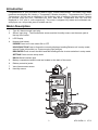
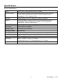
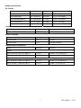
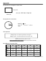
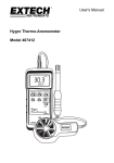
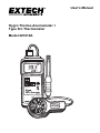
User's Manual Hygro Thermo-Anemometer + Type K/J Thermometer Model 407412A Introduction Congratulations on your purchase of Extech's Hygro Thermo-Anemometer. This Heavy Duty meter measures and displays Air Velocity + Temperature, Relative Humidity + Temperature and Type K/J Temperature. Air flow can be displayed in the following units of measure: feet per minute, meters per second, miles per hour, kilometers per hour, and knots. Temperature and RH units are o o displayed in C/ F and % units respectively. This meter is shipped fully tested and calibrated and, with proper use, will provide years of reliable service. Meter Description 1. Type K/J thermocouple input plug 2. Sensor input plug – The Anemometer sensor and the Humidity sensor use the same jack at the top of the meter. 3. LCD Display 4. Keypad (see below) POWER Press to turn the meter ON or OFF HOLD/FUNCTION Press to freeze the currently displayed reading/Selects unit in setup mode; selects Probe (left position) or Thermocouple (right position) REC/ENTER Press to track the MAX and MIN readings/Press to enter selection in setup mode SETTING Press to enter setup mode RS-232 Serial interface jack 5. Battery compartment and tilt sand are located on the back of the meter 6. Rubber protective jacket 7. Vane Anemometer sensor 8. Humidity sensor 2 407412A-EN v1.1 07/13 Anemometer and Temperature Operation 1. Insert the Vane sensor into the meter's input jack at the top of the meter. 2. Press the POWER button to turn the instrument on and it will automatically recognize the connected probe. 3. The Air Velocity display will default to the settings when the unit was last powered off. 4. To change settings, refer to the Setup Mode described below. 5. For maximum accuracy, the yellow dot must be on the exhaust side of the vane as shown. 6. The meter’s LCD will indicate Air Velocity + Temperature. Setup Mode Press and Hold the SETTING button for >5 seconds to enter setup mode. Use the SETTING Button to select the function listed below. To select the desired unit, press the FUNCTION button. Press the ENTER button to store the selection. Momentarily press the POWER button to exit the setup mode. 1. Unit: Changes the air velocity measurement unit (m/s, km/hr, ft/min, knots, & mile/h). Anemometer probe only. 2. K: Changes the thermocouple type (K or J). Thermocouple probe only. 3. °C: Changes the temperature unit of measure (°C or °F). Anemometer, Humidity, and Thermocouple probes. 4. OFF: Auto Power Off control (Yes/No). Anemometer, Humidity, and Thermocouple probes. 5. Code: Code entering for factory calibration. Relative Humidity and Temperature Operation 1. Insert the Relative Humidity probe in the input jack at the top of the meter. 2. Press the POWER button to turn on the instrument and it will automatically recognize the connected probe. 3. The Humidity mode of operation will default to the settings when the unit was last powered off. 4. To change the temperature units of measure, refer to the Setup Mode described in the previous section of this manual. 5. Hold the probe by the handle in the area to be monitored. The meter will display Relative Humidity + Temperature. 6. Note that humidity measurements take several minutes to stabilize. 3 407412A-EN v1.1 07/13 Type K/J Temperature Operation 1. Insert the thermocouple into the meter's thermocouple input jack at the top of the meter. 2. Press the POWER button to turn the instrument on and it will automatically recognize the connected probe. 3. The Air Velocity display will default to the settings when the unit was last powered off. 4. To change settings, refer to the Setup Mode described in the previous section of this manual. Note: The Thermocouple probe can be inserted into the meter at the same time as the Anemometer or RH/Temperature probe. To alternate between the inserted probes, press and hold the FUNCTION button for more than 2 seconds. Data Hold Press the HOLD button to freeze the displayed reading. The HOLD icon will appear on the LCD while Data Hold is engaged. Press the HOLD button again to resume normal operation. Min/Max Record Mode When selected, the Record mode stores the highest (Max) and lowest (Min) readings for later recall. To use Record mode: 1. Press the REC button. The REC indicator will appear on the LCD display. 2. Start a measurement session. 3. After the measurement session, press the REC button to view the highest (Max) reading recorded. The MAX indicator will appear to inform the user that the displayed reading is the highest value recorded. Momentarily press the HOLD button to continue recording. 4. Press the REC button again to view the lowest reading. The MIN indicator will appear on the LCD to inform the user that the reading displayed is the lowest value recorded. Momentarily press the HOLD button to continue recording. 5. Press and Hold the REC for 2 seconds to return the meter to normal operation. All stored data will be cleared and the REC/MIN/MAX icons will disappear from the LCD. 6. Note that putting the meter into the Record mode defeats the Auto Power Off feature. 4 407412A-EN v1.1 07/13 RS-232 PC Interface The RS-232 serial data port (3.5mm phono jack) is located on the face of the meter. The PC interface hardware is intended for use with the Extech Data Acquisition software package, Part TM Number 407001 which includes Windows 95 / 98 / ME / NT / 2000/ XP compatible software and PC interface cable. For more information, contact Extech or refer to the 407001 User's Manual. Auto Power Off feature The Auto Power Off feature automatically turns the meter off after approximately 10 minutes. This feature can be defeated in Setup Mode described in a previous section of this manual. Battery Replacement When it is time to replace the 9V battery, the low battery indicator appears in the top left-hand corner of the LCD display. Note that reliable readings can be obtained for several hours after the first appearance of the low battery indicator. To replace the battery: 1. Remove the meter's protective rubber holster. 2. Open the battery compartment on the back of the meter using a small coin or a flat blade screwdriver. 3. Replace the 9V battery, close the compartment, and replace the holster. 5 407412A-EN v1.1 07/13 Specifications General Specifications Display Dual function, 4-digit (9999 count) LCD display Units of measure m/s (meters per second), km/hr (kilometers per hour), ft/min (feet per minute), knots (nautical miles per hour), mile/hr (miles per hour); Temperature: °C/°F; Humidity: %RH Data hold Holds reading on the LCD display when button is pressed Sensors Air velocity sensor: Twisted vane arm with low friction ball bearing; Temperature: Precision thermistor; Humidity: Thin film capacitor; Temperature: Type K/J thermocouple Max/Min Record Records highest and lowest readings for later recall Data Output RS-232 serial PC interface Operating Temp. 32°F to 122°F (0°C to 50°C) Operating Humidity Max. 80% RH Power Supply 9V battery Power Consumption Approx 11mADC (Anemometer); 7mADC (RH); 6mADC (Type K/J) Weight 0.77 lbs. (350g) Dimensions Meter: 7.1x2.8x1.3" (180 x 72 x 32mm); Accessories Anemometer/temperature and RH Probes, 9V battery, & case Anemometer Probe: 2.8" (72mm) Diameter x 5.5" (140mm) 6 407412A-EN v1.1 07/13 Range Specifications Air velocity Measurement Range Resolution Accuracy (% of reading) ft/min (feet/min) 80 - 4930 ft/min 1 ft/min ± (2% + 40 ft/min) m/s (meters/sec) 0.4 - 25.00 m/s 0.01 m/s ± (2% + 0.2 m/sec) km/h (kilometers/hour) 1.4 - 90.0 km/h 0.1 km/h ± (2% + 0.8 km/hr) mph (miles/hour) 0.9 - 55.9 mph 0.1 mph knots (nautical miles/hour ) 0.8 to 48.6 knots 0.1 knots ± (2% + 0.4 mph) ± (2% + 0.4 knots) Temperature Range o Resolution o o o o 32 F to 122 F (0 C to 50 C) o Accuracy o o 0.1 F/ C ±1.5 F (±0.8 C) Range Resolution Accuracy 10 to 70% RH 0.1% ±3% RH 70 to 95% RH 0.1% ±(3% rdg ±1%RH) Resolution Accuracy Relative Humidity Thermocouple Temperature Range Type K o o o o -58 F to 2372 F (-50 C to 1300 C) o o o o -327 F to -58 F (-199 C to -50 C) o o o o ± (0.4% + 1.8 F (±1 C)) o o ± (0.4% + 1.5 F (±0.8 C)) o o ± (0.4% + 1.8 F (±1 C)) 0.1 F/ C 0.1 F/ C o o ± (0.4% + 1.5 F (±0.8 C)) o o Type J o o o o -58 F to 2012 F (-50 C to 1100 C) o o o o -327 F to -58 F (-199 C to -50 C) 0.1 F/ C 0.1 F/ C 7 o o o o 407412A-EN v1.1 07/13 Appendix Area equation for rectangular or square ducts Height (H) Area (A) = Width (W) x Height (H) Width (W) Area equation for circular ducts Area (A) = x r2 Where = 3.14 and r2 = radius x radius Radius Cubic equations CFM (ft3/min) = Air Velocity (ft/min) x Area (ft2) CMM (m3/min) = Air Velocity (m/sec) x Area (m2) x 60 NOTE: Measurements made in inches must be converted to feet or meters before using the above formulae. Unit of Measure Conversion Table m/s ft/min knots km/h MPH 1 196.87 1.944 3.6 2.24 1 ft/min 0.00508 1 0.00987 0.01829 0.01138 1 knot 0.5144 101.27 1 1.8519 1.1523 1 km/h 0.2778 54.69 0.54 1 0.6222 1 MPH 0.4464 87.89 0.8679 1.6071 1 1 m/s 8 407412A-EN v1.1 07/13 Warranty FLIR Systems, Inc. warrants this Extech Instruments brand device to be free of defects in parts and workmanship for one year from date of shipment (a six month limited warranty applies to sensors and cables). If it should become necessary to return the instrument for service during or beyond the warranty period, contact the Customer Service Department for authorization. Visit the website www.extech.com for contact information. A Return Authorization (RA) number must be issued before any product is returned. The sender is responsible for shipping charges, freight, insurance and proper packaging to prevent damage in transit. This warranty does not apply to defects resulting from action of the user such as misuse, improper wiring, operation outside of specification, improper maintenance or repair, or unauthorized modification. FLIR Systems, Inc. specifically disclaims any implied warranties or merchantability or fitness for a specific purpose and will not be liable for any direct, indirect, incidental or consequential damages. FLIR’s total liability is limited to repair or replacement of the product. The warranty set forth above is inclusive and no other warranty, whether written or oral, is expressed or implied. Calibration, Repair, and Customer Care Services FLIR Systems, Inc. offers repair and calibration services for the Extech Instruments products we sell. NIST certification for most products is also provided. Call the Customer Service Department for information on calibration services available for this product. Annual calibrations should be performed to verify meter performance and accuracy. Technical support and general customer service is also provided, refer to the contact information provided below. Support Lines: U.S. (877) 439‐8324; International: +1 (603) 324‐7800 Technical Support: Option 3; E‐mail: [email protected] Repair & Returns: Option 4; E‐mail: [email protected] Product specifications are subject to change without notice Please visit our website for the most up‐to‐date information www.extech.com FLIR Commercial Systems, Inc., 9 Townsend West, Nashua, NH 03063 USA ISO 9001 Certified Copyright © 2013 FLIR Systems, Inc. All rights reserved including the right of reproduction in whole or in part in any form www.extech.com 9 407412A-EN v1.1 07/13