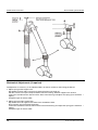
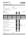
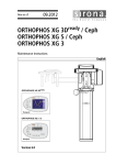
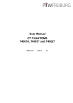
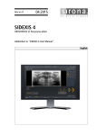
1
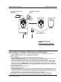
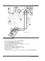
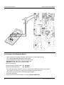
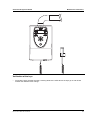
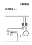
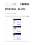
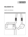
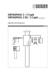
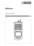
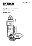
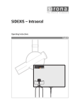
ebiflabkqmirp
j~áåíÉå~åÅÉ=fåëíêìÅíáçåë
US
PL
NT
LI
E
OD
HE
008
. S
7mA DC
70kV 60kV
Maintenance Instructions
Sirona Dental Systems GmbH
ATTENTION!
Adequate lead proofing of room and operator position is
essential.
Since these requirements vary from state to state it is the
assembler's / installer's responsibility that all local radiation
safety requirements are met.
2
62 15 144 D 3507.101.01.02.02
Sirona Dental Systems GmbH
Maintenance Instructions
General
In order to ensure in compliance with the DHHS requirements the HELIODENTmirp must be maintained
annually following date of installation. It is the responsibility of the user to ensure that the equipment is maintained in accordance with the manufacturer's recommended Maintenance Instructions to ensure compliance with the Federal Performance Standard.
The manufacturer and the assembler/installer are not responsible for disturbances in operation when the
equipment is not used in accordance with the operating instructions.
The maintenance inspection and consequent service must be accomplished by a skilled technician.
Neither the inspection nor service is part of the equipment warranty.
Technical instructions required
Operating Instructions and Service Manual
Instruments required
1. Digital multimeter model FLUKE 87 V, or equivalent
Accuracy: AC voltage ± 0.5% of reading plus 1 digit
DC voltage ± 0.1% of reading plus 2 digits
DC current ± 0.3% of reading plus 1 digit
2. Digital Dosimeter,
Model PTW Diados, Nomex or Unfors mult-o-meter
CAUTION RADIATION
Observe radiation protection guidelines as outlined in the Operating Instructions!
ESD
CAUTION Technician!
PC-boards are fitted with electronic components sensitive to electrostatic discharge (ESD).
Electrostatic discharge is unavoidable due to friction of clothing, carpeting etc.
ATTENTION
To prevent damage of electronic components do not touch same.
Discharge your electrostatic energy by touching a grounded point.
Always handle circuit boards by the edge of same.
ATTENTION
WARNING: Electrical shock hazard!
List of Contents
. . . . . . . . . . . . . . . . . . . . . . . . . . . . . . . . . . . . . . . . . . . . . . . . . . . . . . . . . . . . . . . . . . . . . . . . . . . . . . . Page
General . . . . . . . . . . . . . . . . . . . . . . . . . . . . . . . . . . . . . . . . . . . . . . . . . . . . . . . . . . . . . . . . . . . . . . . . . . . 3
Visual Check . . . . . . . . . . . . . . . . . . . . . . . . . . . . . . . . . . . . . . . . . . . . . . . . . . . . . . . . . . . . . . . . . . . . . . . 4
Light Indicators at the Display, Audible Sound at the Wall Adapter. . . . . . . . . . . . . . . . . . . . . . . . . . . . . . 5
Tube Current Verification . . . . . . . . . . . . . . . . . . . . . . . . . . . . . . . . . . . . . . . . . . . . . . . . . . . . . . . . . . . . . . 6
Exposure Time Verification and kV-Verification . . . . . . . . . . . . . . . . . . . . . . . . . . . . . . . . . . . . . . . . . . . . . 7
Verification of the Exposure Button . . . . . . . . . . . . . . . . . . . . . . . . . . . . . . . . . . . . . . . . . . . . . . . . . . . . . . 8
Verification of the keys . . . . . . . . . . . . . . . . . . . . . . . . . . . . . . . . . . . . . . . . . . . . . . . . . . . . . . . . . . . . . . . . 9
Mechanical Adjustments (if required) . . . . . . . . . . . . . . . . . . . . . . . . . . . . . . . . . . . . . . . . . . . . . . . . . . . . 10
Yearly Maintenance Checklist . . . . . . . . . . . . . . . . . . . . . . . . . . . . . . . . . . . . . . . . . . . . . . . . . . . . appendix
62 15 144 D 3507.101.01.02.02
3
Maintenance Instructions
Sirona Dental Systems GmbH
Visual Check
•
Look for mechanical damage, possibly affecting radiation safety.
•
Inspect cone for possible cracks.
•
Check the mechanical functions.
Test the tubehead in all working positions for possible drift.
•
Verify that all labels are affixed and legible.
Defaced labels must be replaced.
To order the above, write to Sirona Dental Systems (address, see rear)
giving details on:
Customer Name
Customer Address
All Model Numbers with
Serial Numbers still legible on the unit for identification purposes.
For serial numbers see also Installation Report / Warranty Passport.
4
62 15 144 D 3507.101.01.02.02
Sirona Dental Systems GmbH
Maintenance Instructions
Standby indicator lamp
Ready LED
Radiation indication
X-ray
Remote Timer
Remote control
Exposure button
ON/OFF
ATTENTION RADIATION
Observe
Radiation Protection Guidelines.
See Operating Instructions.
Light Indicators at the Display, Audible Sound at the Wall Adapter.
•
•
•
•
Switch unit ON with master power switch. The stored exposure data must light up on the display,
see Operating Instructions under ”Preparing the exposure”.
Make an exposure:
– Set the exposure time to 1.00 s for conventional radiography technique.
– CAUTION RADIATION: Depress the exposure button and hold until the exposure terminates automatically. The radiation indication X-ray must light up during the exposure period.
Also the backlight colour of the display must change into yellow. Simultaneously an audible beep
must sound at the wall adapter. In operation with remote control, the wall adapter and the remote
control must imitate an audible beep. The display backlight colour will change automatically from
white into blue, when the cooling down time has finished. Also the value of the imitate X-ray dose will
vanish from the display.
Interrupt an exposure – deadman feature:
– Set the exposure time to 3.2s.
– CAUTION RADIATION: Press the exposure button until X-ray lights up and subsequently release –
the exposure must terminate immediately. The exposure time which had really happen blinks. It can
diversify an depends on the time how long the exposure button was pressed. Press any key on the
front panel to return to the automatic cooling down process on the display.
Defective light indicators constitute a safety hazard to the patient as well as to the operator.
CAUTION: The user is not permitted to use the unit until light indicators have been replaced!
62 15 144 D 3507.101.01.02.02
5
Maintenance Instructions
Sirona Dental Systems GmbH
7 mA ±1.4 mA
Tube Current Verification
•
Turn unit OFF and remove housing (see Service Manual!).
•
Connect multimeter to X600, range 10mADC.
•
Turn unit ON. (WARNING: Electrical shock hazard!)
•
Set the exposure time on the control panel to 3.2s, using the + or - button
(conventional radiography technique).
•
CAUTION RADIATION: Make an exposure.
•
The reading should be 7mADC ±1.4 mA. Record reading.
•
If specified value is obtained turn unit OFF.
•
Remove meter leads!
– If specified value cannot be obtained, see Service Manual, chapter ”Tube Current Verification”.
6
62 15 144 D 3507.101.01.02.02
Sirona Dental Systems GmbH
Maintenance Instructions
Focus marking
SSD = Source to
Skin Distance 8"
SSD
0.40
seC
Dose Detector
Exposure Time Verification and kV-Verification
(conventional radiography technique)
•
•
•
•
•
•
•
•
For testing the exposure times a Digital Dosimeter is required (PTW Diados).
Place the Dose Detector in a distance of 8" in front of the Tube Head.
Switch unit ON.
CAUTION RADIATION! Make an exposure with:
Voltage:
60 kV
Exposure time:
0.4 sec
The reading should be 0.4 sec ±0.04 sec.
kV = 60kV ±6kV. Record reading
Switch unit OFF
If the measured Radiation Time is not within specified tolerance,
see Service Manual, chapter ”Exposure Time Verification”.
If the measured kV Verification is not within specified tolerance,
see Service Manual, chapter ”kV Verification”.
62 15 144 D 3507.101.01.02.02
7
Maintenance Instructions
Sirona Dental Systems GmbH
Verification of the Exposure Button
•
If door contacts are installed, close door (close contacts), do not bridge contacts.
•
Turn unit OFF (WARNING: Electrical shock hazard!)
•
Connect multimeter in range for measuring resistance to:
DX1 X401.1 and 4, when door contacts are not used.
DX1 X401.1 and 2, when door contacts is used
•
Measure resistance:
Exposure button not depressed:
R > 10 kOhm
Exposure button depressed:
R < 100 Ohm
The values must remain constant, even if the coiled cable is moved during the measurement.
•
– If the values are not present, check correct function of the door contacts.
If the values are still not present, exchange exposure button.
•
Disconnect multimeter.
•
Reattach housing (see Service Manual, chapter ”Removing Housing”)
8
62 15 144 D 3507.101.01.02.02
Sirona Dental Systems GmbH
Maintenance Instructions
Verification of the keys
•
Press all the keys one after the other, checking whether the LEDs above the keys go on and off and
whether the radiation times change.
62 15 144 D 3507.101.01.02.02
9
Maintenance Instructions
Sirona Dental Systems GmbH
Mechanical Adjustments (if required)
Readjustment is necessary, if the tubehead does not remain stationary after being positioned.
1. Adjust spring on left support arm:
Slip bellows on both sides over the half shells A. Pull the half shells off.
Pull the scissors arm apart and push bellows over the bearing. Set both support arms vertical.
Insert torx screwdriver from above into the bore of the bearing and adjust the spring (turn clockwise →
tighter).
Complete again in reverse order.
2. Adjust spring on right support arm:
Slip bellows over the upper half shell A. Press the bellows down.
Bring support arm into horizontal position.
Insert torx screwdriver from the front into the bore of the bearing and adjust the spring (turn clockwise →
tighter).
Complete again in reverse order.
10
62 15 144 D 3507.101.01.02.02
ebiflabkqmirp
vÉ~êäó=j~áåíÉå~åÅÉ=`ÜÉÅâäáëí
Customer: ____________________ Address: ________________________________
Dealer: _______________________ Address: ________________________________
Date of original installation: _______ Date of inspection: ________________________
Report of Assembly FD 2579 # ____
SCHEDULE
Yes
No
Remarks
All manuals are present
Test instruments as required
Manufacturer
Model
Accuracy
Last calibrated
Voltmeter
mAmeter
Exposure Time
Any mechanical damage noticed
All labels are present and legible
All indicator lights are O.K.
Radiation indicator X-ray lights up, audible buzzer O.K.
Deadman feature O.K.
Tube current is within specified limits
Measurement: . . . . . mA
Specified exposure time O.K.
Measurement: . . . . .sec
Specified kV Value is O.K.
Measurement: . . . . . kV
Exposure button O.K. Resistance within specified limits
All keys O.K.
Mechanical adjustment of the support arm is O.K.
The unit is in compliance with
MFG specified tests and safety
Technician:____________________ Dealer: _________________________________
62 15 144 D 3507.101.01.02.02
tÉ=êÉëÉêîÉ=íÜÉ=êáÖÜí=íç=ã~âÉ=~åó=~äíÉê~íáçåë=ïÜáÅÜ=ã~ó=ÄÉ=êÉèìáêÉÇ=ÇìÉ=íç=íÉÅÜåáÅ~ä=áãéêçîÉãÉåíëK
«=páêçå~=aÉåí~ä=póëíÉãë=dãÄe=OMMV
a=PRMTKNMNKMNKMOKMO===MTKOMNM
péê~ÅÜÉW=ÉåÖäáëÅÜ=
ûKJkêKW= NNO=RTM
mêáåíÉÇ=áå=dÉêã~åó
fãéêáã¨=Éå=^ääÉã~ÖåÉ
páêçå~=aÉåí~ä=póëíÉãë=dãÄe
áå=íÜÉ=rp^W
c~Äêáâëíê~≈É=PN
SQSOR=_ÉåëÜÉáã
dÉêã~åó
ïïïKëáêçå~KÅçã
páêçå~=aÉåí~ä=póëíÉãë=ii`
QUPR=páêçå~=aêáîÉI=pìáíÉ=NMM
`Ü~êäçííÉI=k`=OUOTP
rp^
lêÇÉê=kç
SO=NR=NQQ=a=PRMT