1
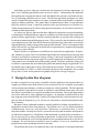
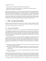
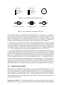
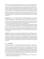
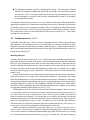
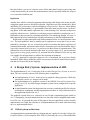
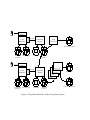
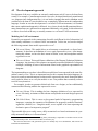
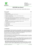
ADL: A Graphical Design Language
for Real-time Parallel Applications
Maarten VAN STEEN
Erasmus University Rotterdam, Department of Computer Science
POB 1738, 3000 DR, Rotterdam
Teus VOGEL, Armand TEN DAM
TNO Institute of Applied Physics, POB 155, 2600 AD, Delft
Abstract. Designing parallel applications is generally experienced as a tedious and difficult task, especially when hard real-time performance requirements have to be met. This
paper discusses on-going work concerning the construction of a Design Entry System
which supports the design phase of parallel real-time industrial application development.
In particular, in this paper we pay attention to the development and implementation of a
graphical Application Design Language. The work is part of the ESPRIT project Hamlet which focuses on industrial application of transputer-based systems for commercial
strategic real-time applications.
1 Introduction
Over the last twenty-five years concurrency has become one of the most active areas of research in computer science. Concurrent models have been widely applied in the design of operating systems and databases, and as efficient implementations of high-level concurrent languages became available, software that was originally coded in an assembly language could
now be developed using high-level language constructs yielding well-structured, efficient, and
portable implementations. As insight in the behavior of concurrent models grew, focus has
gradually shifted from the problem of developing programs that behave in a well-defined manner to that of developing programs that exploit parallelism to improve overall efficiency. This
shift of focus has brought us, somewhat surprisingly, to a stage comparable to the first stages of
research in concurrency issues. At the moment, parallel applications are generally written in
a highly machine-dependent manner and often violate basic rules of well-structured software
in order to retain efficiency [13].
And indeed, developing parallel programs is generally experienced as a difficult and tedious task in comparison to the development of sequential programs. This is not too surprising if one considers the additional requirements that are currently demanded from a parallel
application developer. In the first place, he or she must concentrate on the specification of an
algorithm such that parallelism can be exploited to a maximum extent. This requires a priori
insight in the parallel aspects of the problem to be solved. More serious, however, is the fact
that deriving an actual implementation requires that the developer also has knowledge concerning the semantics of communication and synchronization mechanisms, as well as knowledge concerning the target parallel computer on which the algorithm is to be executed [1].
And things get worse when one considers the development of real-time applications. In
these cases, exploiting parallelism seems an obvious choice. Unfortunately, the additional
hard performance requirements that are often demanded in the real-time world make the process of exploiting parallelism no less easier. Besides that application developers are often
forced to exploit the target machine to its edges, communication itself should be completely
subject to timing constraints. This means that if communication within a certain timespan
failed for whatever reason, it should be possible to take special measures in a flexible way.
Timed communication and its effects on program development is an issue that is obsolete in
scientific parallel applications.
As it turns out, practice indicates that these additional requirements are quite demanding.
Considering the fact that hardly any support is available to assist the structured development of
parallel real-time applications, it is not too surprising that there is currently still a strong need
for advanced monitoring and debugging systems. This is caused by the fact that the results of
a development process can often only be measured in the final stage when a first version of the
implementation is actually running on the target parallel machine. This is not an approach that
can be followed for very long and as such has been recognized by the companies participating
in the ESPRIT project Hamlet.
Hamlet focuses on exploitation of parallelism for hard real-time applications. In particular, attention is paid to industrial embedded applications for transputer-based systems and
which are developed for commercial strategic reasons. It has been recognized by the Hamlet
consortium that advanced practical support for parallel application development is necessary
if the partners are to maintain their strong market position. Therefore, attention is being paid
to software components that assist during the global and detailed design of applications. It is
beyond the scope of this paper to discuss the Hamlet project in detail. To that aim, we refer the
interested reader to [8]. Here, we shall concentrate on just one such component: the so-called
Design Entry System, and in particular its graphical Application Design Language.
2 Design by data flow diagrams
In order to support the design phase of parallel real-time application development there are
roughly two extremes that can be followed: one can choose to devise a complete new method
with accompanying techniques, or otherwise simply use existing methods. The first approach
not only requires a great deal of research, it can also be expected that at best many years will
pass before a new method is accepted in an industrial environment. The second approach has
so far been followed by many application developers. In particular, methods based on data
flow diagrams such as introduced by Yourdon [22] and specifically extensions thereof to support real-time development (e.g. [10, 19]) are now often used as common development methods in industry.
But none of these traditional methods is actually suitable for dealing with parallelism, although their inventors often claim otherwise. The problem, as we see it, is that no distinction
is made between concurrency and parallelism. Concurrency, as viewed by us here, is a technique that enables a developer to model a system in such a way that its structure and dynamics
are reflected in a natural way. Parallelism, on the other hand, is considered by us a means to exploit a target machine to meet performance requirements. In other words, where concurrency
focuses on modeling the real world, parallelism focuses on implementation for a specific environment. The two need not necessarily be easy to combine. As we see it, concurrency and
parallelism are often mistakenly taken to be the same.
The problem that needs to be addressed then is the development of a design method and
supporting tools which:
are familiar to developers of industrial real-time applications,
are based on methods that have proved to be applicable in an industrial context,
deal with concurrency and parallelism.
Based on these requirements, we have chosen to support parallel real-time application development based on data flow diagrams (DFDs). However, where DFDs are generally used in the
analysis and architectural design phase of a development project, we have adapted them in
such a way that they are more suitable for physical and detailed design [6, 7]. In particular,
emphasis has been put on the support for design of different communication structures, grouping of activities into processes, and integration of data and control transformations. This has
resulted in a first version of an Application Design Language, referred to as ADL/1.
3 ADL: Concepts and notations
In this section we discuss the main concepts of ADL: processes, activities, and how communication is dealt with. In addition, we present features which are still under development but
which will be incorporated in a next version of ADL.
3.1 Processes and activities
A key concept of ADL is that of activities. An activity is used to model a logical entity capable
of transforming incoming data which can then be passed on to another activity. Similar to the
approach followed in Mascot [16], the interface of each activity is entirely specified by means
of a collection of gates. Gates specify explicit access points to communicate data or tokens to
or from an activity, and as such provide the essential means to connect activities to each other
in a structured manner.
From the activity’s point of view, data or tokens can either be sent to the outside world
by means of an output gate, or, conversely, can be received through a so-called input gate. In
order to separate the concerns of how and when communication should take place, gates are
subject to timed communication. Timed communication is used to specify when communication through a gate should take place. Three types of timed communication are available in
ADL:
blocked communication, meaning that an activity cannot proceed until data or token
transfer has actually taken place;
non-blocked communication, meaning that if communication could not take place immediately the activity will proceed without further delay and without transferring any
data or tokens;
delayed communication, in which case communication should start within a specified
amount of time units.
Blocked and non-blocked communication are in fact special cases of delayed communication. If ∆t denotes the specified time an activity is willing to wait before communication takes
place, then clearly the case ∆t = 0 corresponds to non-blocked communication whereas the
case ∆t = ∞ is the same as blocked communication. For practical reasons, we have chosen
to incorporate all three communication types. Also note that these forms of communication
input gates:
output gates:
blocked
non-blocked
delayed
blocked
non-blocked
delayed
Figure 1:
ADL
synchronous channel
Figure 2:
ADL
activity
notations for gates and activities.
message queue
semaphore
notations for communication media.
relate to the moment when communication should take place as required by the communicator and if this requirement could not be met communication is cancelled all together. This is
different from (a)synchronous communication which involves all communicating parties, and
which is, in principle, never cancelled. In the next subsection we shall discuss a number of
examples in which timed and synchronous forms of communication are combined.
Activities are represented as circles with input and output gates drawn as respectively small
circles and black boxes, as shown in Figure 1 (the blocked, non-blocked, and delayed gates
are explained shortly). Although the current implementation of ADL supports a simple means
of hierarchical design, it has not been formally incorporated into the language definition of
ADL/1. This omission has been corrected in the updated version of ADL (see [17]).
Activities are appropriate for logical design decisions: they represent logical entities that
act concurrently. In practice, the number of activities that act concurrently may not correspond
to what is desired from an implementation point of view. To that aim, activities can be grouped
into processes, intended to be the actual units of parallel behavior in the final implementation.
From a conceptual point of view, a process is just another activity, i.e., it models a transformation entity which communicates with other processes by means of gates. The main difference
between an activity and a process is that the latter constitutes inherent sequential behavior,
despite the number of activities it may contain. In other words, processes form the means to
add sequential behavior in order to fit the logical design in an implementation environment.
3.2 Communication media
Where gates in ADL designs are used to specify when communication should take place, communication media specify how communication should proceed. ADL/1 supports three types of
communication media: synchronous channels and message queues for communicating data,
and semaphores for communicating tokens. Communicating tokens effectively establishes
synchronization between a collection of activities. Figure 2 shows the notations for the various communication media.
Synchronous channels. A synchronous channel is used to model point-to-point communication between two activities and corresponds to the standard synchronous communication
means in most message-based programming languages [4]. A synchronous channel is modeled as a directed edge between the output gate of a sending activity, and an input gate of a
receiving activity. The important thing to note about synchronous channels is that their functionality is primarily determined by the lack of buffering capabilities. In other words, if two
activities communicate data through a synchronous channel, both sender and receiver will
have to synchronize. When communication may take place is determined by the gates of the
respective activities. For example, imagine a scenario in which a sender wants non-blocked
synchronous communication, while the receiver has chosen for blocked (synchronous) communication. In this case, the sender will only transmit data whenever the receiver is capable
of accepting that data. On the other hand, the receiver will block until the data is actually
transmitted.
Message queues. ADL/1 also provides support for modeling asynchronous communication
by means of message queues. Message queues in ADL/1 are buffers that act on a first-come
first-serve basis and may have either an infinite or finite capacity. Several activities may be
connected to a message queue, in particular, an activity that wants to put data into a queue has
an arc between one of its output gates and the tail of the queue, while a reading activity will
have an arc between the head of the queue and one of its input gates.
Again, note how the gates determine the conditions under which communication can take
place. For example, imagine a message queue Q with finite capacity connected to an output
gate of an activity A. Suppose that at time t0 activity A wants to append data to Q according to
a delayed communication protocol such that communication should take place before ∆t time
units have elapsed. If at time t0 the queue was full, then this form of timed communication
specifies that if A cannot append its data before t0 + ∆t, it will simply cancel the communication all together.
Semaphores. Finally, ADL/1 also supports (counting) semaphores. Obviously, our concept
of gates enhances the traditional semantics of semaphores. For example, a conditional waitoperation [2] is modeled as a combination of a non-blocking input gate and an ordinary waitoperation: if the requesting activity cannot retrieve a semaphore token immediately (normally
implying that it should wait), it simply continues without further delay. Conditional semaphores
are typically used in time-critical applications: a simple trade-off is made between entering a
critical region (for which the activity should acquire the token), or otherwise to continue with
other tasks.
3.3 An example
To illustrate the use of ADL, consider the following problem inspired by a description discussed in [5]. Envisage a system for monitoring temperatures consisting of a single sensor.
The sensor distinguishes a number of different states (e.g., enabled/disabled) and can be tuned
by setting a number of attributes (e.g., temperature range, sampling frequency, etc.). In the
event of an out-of-limits value, the system will immediately post an alarm condition. Additionally, the status of the sensor should be recorded every fifteen mintes (indicated through a
timer). If the sensor does not respond within five seconds after this time, it is assumed it is
broken and another alarm condition is posted. Finally, it is assumed that operators may pass
commands to the system for setting the attributes of the sensor.
Using the current implementation of ADL, we can design the system as shown in Figure 3.
The following activities are distinguished:
Figure 3: An example of an ADL design as constructed with the current implementation.
The Sensor activity represents the actual sensor. We assume that it periodically appends the registered temperature into a message queue for further analysis. Also, using
non-blocked communication, the sensor is assumed to periodically check if any of its
attributes should be set. Note how the communication with activity Monitor has been
modeled: if Monitor is not sending any attribute information through the synchronous
channel sensor attribute, the sensor will immediately continue without further delay.
The Temperature Logging activity removes registered values from the message queue
through which it communicates with the sensor. If values are out of limit, it posts an
alarm, modeled by means of the semaphore out-of-limit.
The Monitor activity is at the heart of the system. Note the delayed communication modeled with resepct to the synchronous channel sensor status. In this way, we model the
fact that if a sensor does not respond within five seconds when Monitor is requesting
the status of the sensor, it cancels the communication and concludes that the sensor is
broken. Furthermore, we assume that Monitor periodically checks if there are any outstanding commands from an operator. Again, we have chosen to use non-blocked communication with message queue command for this purpose.
The Timer activity models the system clock. The non-blocked form of communication
with semaphore time represents the fact that at no cause the system clock should be delayed. It has been assumed that the Monitor activity will eventually synchronize on the
time semaphore.
The Operator and Alarm activities complement the design. The interaction of Alarm
with the two semaphores defect and out-of-limit is intended to be modeled by means of
an alternative choice: at any time, Alarm will be waiting for synchronization by any of
the two semaphores. In practice, this would be implemented by means of, for example,
an alt-statement in occam.
The example illustrates that activities in ADL are considered somewhat different from those
appearing in standard DFDs. Rather than considering an activity as a function to be performed
(reflected by using verbs as a naming convention), they are considered as independent objects
in ADL. For this reason, we feel it to be more appropriate to identify them by means of nouns.
The example also reveals several shortcomings of the current version of ADL. These shortcomings are discussed next.
3.4 Enhancements to ADL/1
It should be clear that ADL/1 lacks at least two important features: behavioral specification
and replication. We shall discuss these two issues briefly here, but note that behavior modeling and replication are still subject to debate within the project. Actual implementation of
these concepts has been deliberately deferred to a later stage; initial definitions have, however,
already been proposed [17].
Modeling behavior
Activities form the units of behavior in ADL/1, and obviously there should be a means for supporting the description of behavioral aspects. In most methods based on data flow diagrams,
there is a strict distinction between data activities and control activities. Data activities are
used for modeling data transformations, whereas control activities describe the system’s flow
of control. In order to describe data transformations, pseudo-code, or sometimes even a highlevel procedural language is used. Control flow is described by means of state-transition diagrams (STDs).
A major drawback of DFDs (or function/data models in general) is that a strict distinction is
made between data objects, and functions that transform that data. Consequently, any change
in the data definition may severely affect the definition of functions. Furthermore, when separating control and data transformations, the process of integrating them (which is required for
an implementation) may turn to be less straightforward than one would expect. These considerations have led us to integrate data and control transformations into a single activity, making
our approach essentially object-based (see also [12, 21]).
Modeling behavior in ADL is done by means of state-transition diagrams. However, where
STDs normally consist of a single notion of a state, and transitions between states can only occur as the result of an event, we have chosen to use a form of STDs by which a developer can
focus on communication entirely. This means that we are initially not interested in data and
control transformations which do not immediately relate to communication. This perspective
has led us to distinguish two types of states. Communication states describe the situation in
which an activity is involved in communicating data or tokens through one of its gates; processing states are used for modeling data transformations exclusively.
In order to model state transitions, a gate raises either a success event or a timeout event. A
success event is raised whenever a datum or token passes through the gate, whereas a timeout
event is raised whenever communication through the gate failed. When an activity is residing
in a communication state associated with, say, gate g, it can only leave this state after gate g
has raised either a success or a timeout event. On the other hand, leaving a processing state
is fully determined by the actual data transformation (which is specified outside the scope of
STDs) associated with that state.
Replication
Another issue which is extremely important when dealing with design is the means for indicating that certain processes should be replicated. Replication was also introduced by Ward
and Mellor [20] as a means to indicate multiplicity of functionality. However, when dealing
with specifying functionality it is questionable what replication actually means. In the design phase, on the other hand, replication has a clear meaning if we associate each process
explicitly with an instance. And this is exactly how processes should be considered in ADL/1.
Replication is thus a means for exploiting parallelism. The underlying thought, of course, is
that replicated processes indeed return as replicated instances in the final implementation.
Replication is a subject that stills needs further attention before we can incorporate it into
ADL. The main problem is how to actually specify replication in a way that is easy to comprehend by a developer. As ADL is based on a model of execution that makes explicit use of
communication media, replication cannot only be restricted to processes but should be able to
cope with communication structures, i.e. processes and their means of communication. This
problem has received much attention in the form of graph grammars [14], and in particular
aggregated rewriting graph grammars [3], and turns out to be difficult to solve in a way that
is acceptable for incorporation in a software development environment.
In [17] a proposal for replication support in ADL is formulated, but as we have already
mentioned, further debate within the project is necessary to decide the actual form of replication that is to be provided by the language.
4 A Design Entry System: implementation of ADL
The implementation of ADL/1 forms part of the so-called Design Entry System, or
short. The DES basically consists of the following three components:
DES
for
An implementation of ADL/1 in the form of a graphical editing system by which only
syntactically correct ADL designs can be made.
An implementation of a graphical version of the INMOS Network Description Language (NDL) [11], by which a target transputer system can be configured for a specific
application.
A transformation system which generates the necessary configuration files for software
and hardware components, and the mapping between them, as well as skeletal code for
the application described in ADL/1.
The graphical version of the NDL, referred to as NDL/Graph is implemented quite similar to
ADL. Conceptually, it is much simpler than the ADL due to the relative straightforward semantics of the NDL. It is beyond the scope of this paper to discuss in detail how we have actually
implemented NDL/Graph, but reference to its implementation will be made when discussing
the ADL implementation below.
4.1 Global system architecture
A component that is paramount in the DES from an end user’s point of view is the Configurable
Graphical Editor (CGE) developed at TNO-TPD [18]. Basically, the CGE is a 2D customizable
CGE
KERNEL
Access
interface
Window
manager
TCP/IP
SD-3
SD-2
SD-1
S1.3
S1.2
S1.1
Diagram
definitions
Diagrams
Figure 4: Global architecture of a customized version of the CGE.
multi-window graphical editor that can be adapted for a wide range of diagram techniques.
The CGE customizes itself after it has been provided with a correct diagram technique definition file. This file contains a description of all symbols and rules associated with a specific diagram technique, using a special definition language, the Diagram Technique Definition Language (DTDL). A diagram technique is defined by describing the graphical symbols, the possible manipulations on these symbols, the possible interconnections between the symbols and
the constraints with respect to the structure of a diagram. All these aspects are integrated into
the DTDL. In the case of our DES, two diagram techniques will be supported: one for ADL,
and one for NDL/Graph. The architecture of a customized CGE is depicted in Figure 4.
When customized for a specific application, the CGE assists the user in constructing diagrams in such a way that only syntactically correct diagrams can be constructed. Semantics
associated with a diagram technique are to be verified by additional tools that communicate
with the CGE through a TCP / IP interface. To this aim, a datastructure capturing the same information as the original diagram should be constructed, but which can now be accessed by
external applications. This datastructure is generated automatically by what we refer to as an
Abstract Data Type (ADT) builder.
In our case, the ADT builder actually creates instances of an abstract data type describing
ADL. In other words, this abstract data type is yet another definition of ADL. This definition
itself is also generated in an automated fashion by the CGE, as will be further explained below.
Returning to the Design Entry System, we are now able to expose its entire global architecture. Two main subarchitectures can be distinguished as depicted in Figure 5: one that
deals with graphically configuring a target transputer system, and one that handles the design of applications using ADL. Similar to the ADL subsystem, the NDL subsystem generates instances of the so-called NDL Abstract Data Type. These datastructures are used by the
ADL / ADT builder to relate processes as described in an ADL design to transputers, and to add
this mapping information in an ADT instance. Mapping information is assumed to be provided
manually when designing an application in ADL, given a description of the target hardware
expressed in NDL/Graph. Using the ADL / ADT instances as input, several additional tools are
invoked that eventually produce a set of configuration files by which the application can be
loaded onto the target network, as well as a set of files containing skeletal code for each of the
processes to be executed.
CGE
KERNEL
Access
interface
Window
manager
TCP/IP
NDL/ADT
Builder
NDL.3
NDL.2
NDL.1
NDL
Generator
Network descriptions
SD-3
SD-2
SD-1
S1.3
S1.2
S1.1
ADT.3
ADT.2
ADT.1
NDL
ADT
NDL/DTDL NDL Diagrams
definitions
NDL/ADT
NDL/ADT
Instances
Window
manager
CGE
KERNEL
SD-3
SD-2
SD-1
ADL/DTDL
definitions
Access
interface
C.3
C.2
C.1
TCP/IP
ADL/ADT
Builder
S1.3
S1.2
S1.1
ADL
ADT
ADL diagrams
ADL/ADT
Source Code
Generator
Configuration
Generator
Semantic
Checker
Syntax
Checker
Source codes
SDL.3
SDL.2
SDL.1
ADT.3
ADT.2
ADT.1
ADL/ADT
Instances
Software descriptions
Figure 5: The global architecture of the Design Entry System.
4.2 The development approach
Development of the DES would be an extremely cumbersome task if it was to be done from
scratch. For example, if transformation tools were to be developed that directly transformed
ADL diagrams into configuration files, it is not hard to imagine that much redundant work
would need to be done if it was decided to use a completely different network configuration
language. In order to ease the development of CGE-based CASE environments, it is essential
that a more sophisticated approach is followed. As we have already briefly mentioned above,
many datastructures are generated in an automated fashion by our system. In this subsection
we take a closer look at the way we actually construct a CGE-based CASE environment.
Modeling the CASE environment.
Essential in our approach is the construction of models (at different levels of abstraction) of
what actually constitutes a CGE-based CASE environment. To this aim, we have developed
the following semantic data models expressed in NIAM1 .
The NIAM Schema. This model allows us to bootstrap a customized CGE-based environment. It describes our definition of NIAM, again expressed in NIAM. After instantiating this schema, we have the basic means to define, create, and manipulate models
expressed in NIAM.
The DTDL Schema. This model forms a definition of the Diagram Technique Definition
Language. Any instance of this schema corresponds to an actual definition of a diagram
technique, including all sorts of information related to the graphical representation of
diagrams.
The important thing to note here is that all these models have been expressed in the same formalism, namely NIAM. This is an important issue for this common description language allows us to construct transformations to other models expressed in the same formalism rather
easily, and also allows us to verify the models we use. Our problem thus essentially reduces
to model transformations.
For example, in order to generate skeletal code from ADL designs, we have additionally
constructed the following models also expressed in NIAM:
The
Schema. This is nothing else but a language definition of ADL expressed in
NIAM. Obviously, an instance of this schema corresponds to an actual design expressed
in ADL.
ADL
The Code Schema. This is a more or less general model of imperative programming
languages, capturing the semantics of declarations for programs, modules, functions,
arguments, variables, etc. Using this model, we are capable of at least expressing the
declarative parts of an imperative program2 .
These models allow us to easily create a fully customized CGE-based environment in a partially automated fashion, as is discussed next.
1 NIAM
is a formal method based on modeling binary relationships, comparable to extended versions of the
Entity-Relationship model. The interested reader is referred to [15].
2 We note here that source code generation by the DES initially only covers declarations, and sections for
initialization and finalization.
Semi-automated construction of the DES.
Concentrating on the construction of the DES subarchitecture that supports development of
ADL designs, we have implemented ADL/1 by proceeding according to the following steps.
Step 1. We start by defining the concepts of ADL using the DTDL. This step results in a
textual description of ADL expressed in DTDL. This description of ADL is needed only to customize the CGE so that we can actually draw diagrams. Not surprisingly, this description is
entirely aimed at the concrete graphical syntax of ADL.
Step 2. The second step is entirely automated by means of the ADT builder. It involves the
following activities:
2a. The builder starts with instantiating a NIAM model of NIAM resulting in an internal
datastructure that allows us to define, create, and subsequently manipulate models expressed in NIAM.
2b. It then continues with loading our NIAM model of the DTDL definition, or, in other words,
instantiating the previously generated datastructure for NIAM models. At this point we
are now capable of creating and manipulating diagram technique definitions expressed
in DTDL.
2c. Finally, our textual description of ADL from the first step is parsed by the generator and
created as an instance of our NIAM model of the DTDL. In other words, the ADT generator fills in the datastructure that resulted from Step 2b with the specific ADL diagram
technique definition, now allowing us to actually create and manipulate ADL diagrams.
The result is what we have previously referred to as the ADL/ADT.
Note how Steps 2a and 2b correspond to generating a database for storing and manipulating
models expressed in some general model definition language (in our case DTDL). Step 2c then
corresponds to customizing such a database so that models expressed in a specific formalism
can be created and manipulated (in our case ADL). Returning to the previously mentioned
interface layer of the CGE, we can now state that this is, in fact, nothing but a data definition
and manipulation language for model bases, albeit rather primitive.
Step 3. This step involves explicitly relating the ADL description expressed in DTDL to the
one expressed in NIAM and consists of two activities. In the first place, we load the NIAM
model of ADL (i.e. the ADL Schema) into the system, or, in other words, we instantiate yet
another NIAM model of NIAM similar to what was done in Step 2b. Furthermore, we develop
a parser that transforms any ADL diagram description in terms of DTDL to one expressed in
NIAM according to ADL Schema.
Step 4. The fourth step consists of loading the Code Model (which was also expressed in
NIAM) into the system.
Step 5. Finally, we concentrate on the development of a component which transforms an
ADL diagram expressed as an instance of a NIAM model of ADL, into an instance of the Code
Schema. This step, so far, is the most time-consuming in the construction of a CGE-based
CASE environment. Also, this fifth step deals with developing the actual source code generators for C, occam, or NDL.
Our development process is depicted in Figure 6. Summarizing, by using a common description language (in our case NIAM), we have been able to actually reduce the effort of developing
a CGE-based CASE environment to the development of a transformation system that acts on
instances of the ADL/ADT, and to construct code generators for the actual target languages C,
occam, and NDL.
5 Current results and future work
Due to the fact that the application developers in the Hamlet project are in need of any support they can get during the design phase of their applications, we have decided to follow an
incremental approach with respect to developing the DES. At present, a graphical editor for
ADL (as well as NDL/Graph) has been completed and has been released to the application developers. The editor allows to attach code to an activity using an ordinary text editor. This
code describes the behavior of an activity.
We have completed a preliminary version of a source code generator which generates a
parallel version of C based on Parsytec’s RTSM communication library [9]. At the moment,
we are able to transform a complete design expressed in ADL (and augmented with code describing the behavior of activities as mentioned above) into C code. The resulting program
is then compiled and linked with a simulator to obtain a preliminary evaluation of the performance. Also, graphical descriptions of transputer networks can be built and transformed
into NDL code. When considering the fact that our actual implementation work started in the
beginning of this year with a team consisting of one senior and one junior software engineer,
we feel confident that our development approach as sketched above is indeed a feasible one
for rapidly developing a customized CASE environment. It is also clear that this approach allows us to concentrate on the essence: the transformation of ADL designs to source code and
configuration files.
Acknowledgements
We thank Jaap Gordijn (TNO-TPD) for carefully reading the initial version of the manuscript,
as well as the two anonymous referees who have suggested several improvements. Special
thanks also goes to Reino de Boer and Eelco van Asperen for their comments and assistance
in preparing the final version. This work has been conducted as part of the ESPRIT project
Hamlet (P6290) and is partially funded by the Commission of the European Communities.
References
[1] G.R. Andrews. Paradigms for Process Interaction in Distributed Programs. Computing Surveys,
23(1):49–90, 1991.
[2] M.J. Bach and S.J. Buroff. Multiprocessor UNIX Operating Systems. AT&T Technical Journal,
63(8, part 2):1733–1749, October 1984.
[3] D.A. Bailey and J.E. Cuny. An Approach to Programming Process Interconnnection Structures:
Aggregate Rewriting Graph Grammars. In J.W. de Bakker and A.J. Nijman and P.C. Treleaven,
editor, PARLE: Parallel Architectures and Languages Europe, volume 2 of Lecture Notes in Computer Science 259, pages 112–123. Springer-Verlag, Berlin, 1987.
CONSTRUCT
DIAGRAM WITH
CGE
DEFINE ADL
IN DTDL
ADL DEFINITION
IN DTDL
DEVELOP
PARSER
ADL DIAGRAM
PARSER
ADL/ADT
ADL/ADT
INSTANCE
ADL
SCHEMA
DEVELOP
MODEL
TRANSFORMER
TRANSFORMER
CODE
SCHEMA
DEVELOP
CODE GENERATOR
CODE
INSTANCE
GENERATOR
SOURCE
CODE
MANUALLY
CONSTRUCTED
DATASTRUCTURE
GENERATED
DATASTRUCTURE
DEPENDENCY
RELATIONSHIP
RESULT OF MANUAL
CONSTRUCTION
MANUALLY
CONSTRUCTED
COMPONENT
MANUAL ACTIVITY
DATAFLOW
Figure 6: The DES development process.
[4] H.E. Bal, J.G. Steiner, and A.S. Tanenbaum. Programming Languages for Distributed Computing
Systems. Computing Surveys, 21(3):261–322, 1989.
[5] G. Booch. Software Engineering with Ada. Benjamin/Cummings, Menlo Park, Calif., 1983.
[6] J.E. Cooling. Software Design for Real-time Systems. Chapman & Hall, London, 1991.
[7] R.E. Fairley. Software Engineering Concepts. McGraw-Hill, 1985.
[8] HAMLET. Application Requirements. HAMLET Technical Report, AEG Electrocom, Konstanz,
Germany, September 1992.
[9] HAMLET. RTSM Description and Preliminary User Manual. HAMLET Technical Report,
Parsytec Industriesysteme, Aachen, Germany, January 1993.
[10] D.J. Hatley and I.A. Pirbhai. Strategies for Real-Time Specifications. Dorset House, New York,
1987.
[11] N. Haydock. NDL Hardware Configuration Language Reference Manual. Internal Technical
Report SW-0308-10, INMOS Limited, June 1992.
[12] I. Jacobson. Object-Oriented Software Engineering, A Use Case Driven Approach. AddisonWesley, 1992.
[13] A.H. Karp. Programming for Parallelism. Computer, pages 43–57, May 1987.
[14] M. Nagl. Graph-Grammatiken, Theorie, Implementierung, Anwendungen. Vieweg, Braunschweig, 1979.
[15] G.M. Nijssen and T.A. Halpin. Conceptual Schema and Relational Database Design, A Fact
Oriented Approach. Prentice-Hall, 1989.
[16] H.R. Simpson. The Mascot Method. IEE Software Engineering Journal, 1(3):103–120, May
1986.
[17] M.R. van Steen. An Introduction to the Hamlet Application Design Language, version 1.0. Hamlet Technical Report, Erasmus University Rotterdam, Department of Computer Science, 1993. In
preparation.
[18] T. Vogel. Configurable Graphical Editor, Users Guide. Technical Report 91 ITI 382, TNO Institute of Applied Computer Science, Delft, February 1991.
[19] P.T. Ward. The Transformation Schema: An Extension of the Data Flow Diagram to Represent
Control and Timing. IEEE Transactions on Software Engineering, SE-12(2):198–210, 1986.
[20] P.T. Ward and S.J. Mellor. Structured Development for Real-Time Systems. Yourdon Press, Englewood Cliffs, N.J., 1985.
[21] P. Wegner. Concepts and Paradigms of Object-Oriented Programming. OOPS Messenger, 1(1):7–
87, 1990.
[22] E. Yourdon and L.L. Constatine. Structured Design: Fundamentals of a Discipline of Computer
Program and System Design. Prentice-Hall, Englewood Cliffs, N.J., 1979.