1
2235
ADJUSTMENT MANUAL
This Adjustment Manual is valid for machines
from the following serial numbers onwards:
# 2 799 145
296-12-19 218/002
Justieranleitung engl. 09.12
The reprinting, copying or translation of PFAFF Adjustment Manuals, whether in whole or
in part, is only permitted with our previous authorization and with written reference to the
source.
PFAFF Industriesysteme
und Maschinen AG
Hans-Geiger-Str. 12 - IG Nord
D-67661 Kaiserslautern
Index
Contents ................................................................................ Page
1
1.01
Adjustment ........................................................................................................................... 4
Notes on adjustment ............................................................................................................. 4
1.02
1.03
1.04
1.05
1.05.01
1.05.02
1.05.03
1.05.04
1.05.05
1.05.06
1.05.07
1.05.08
1.05.09
1.05.10
1.05.11
1.05.12
1.05.12.01
1.05.12.02
1.05.13
1.05.13.01
1.05.13.02
1.05.13.03
1.05.13.04
1.05.14
1.05.15
1.05.16
1.05.17
1.05.18
1.06
1.06.01
1.06.02
1.06.03
1.06.04
1.06.05
Tools, gauges and other accessories for adjusting .......................................................... 4
Abbreviations ......................................................................................................................... 4
Explanation of the symbols .................................................................................................... 4
Adjusting the basic machine .................................................................................................. 5
Basic position of the balance wheel (adjustment aid) ............................................................ 5
Balance weight ...................................................................................................................... 6
Zero position of the unison feed ........................................................................................... 7
2
2.01
2.02
2.03
Feeding motion of the unison feed ....................................................................................... 8
Lifting motion of the bottom feed dog ................................................................................... 9
Height of the bottom feed dog ............................................................................................ 11
Feeding stroke difference .................................................................................................... 12
Preliminary adjustment of the needle height ....................................................................... 13
Needle rise, hook clearance and needle height ................................................................... 14
Top feed stroke .................................................................................................................... 15
Top-feed lifting motion ......................................................................................................... 16
Adjusting the potentiometer for speed reduction ................................................................ 17
On machines with drive P45 PD2-L and P74 ED-L.............................................................. 17
On machines with drive PF 321 ........................................................................................... 17
Machine drive home position ............................................................................................... 18
On machines with drive P45 PD2-L ..................................................................................... 18
On machines with drive P74 ED-L ....................................................................................... 18
On machines with drive AB 321 .......................................................................................... 19
On machines with drive PF 321 ........................................................................................... 19
Bobbin winder ...................................................................................................................... 20
Thread check spring and thread regulator ............................................................................ 21
Sewing foot pressure........................................................................................................... 22
Lubrication ........................................................................................................................... 23
Limiting the stitch length ..................................................................................................... 24
Adjusting the thread trimmer -900/91 .................................................................................. 25
Basic position of the thread trimmer ................................................................................... 25
Control cam to roller lever clearance (resting position) ........................................................ 26
Adjusting the control cam .................................................................................................... 27
Knife pressure ...................................................................................................................... 28
Manual cutting test .............................................................................................................. 29
Circuit diagrams ................................................................................................................. 30
Block diagram PFAFF 2235 PLUS with control pack P45 PD-L ............................................ 30
Block diagram PFAFF 2235 PLUS with AB 321 ................................................................... 31
Circuit diagrams ................................................................................................................... 32
Adjustment
1
Adjustment
Please observe all notes from Chapter 1 Safety of the instruction manual!
In particular care must be taken to see that all protective devices are refitted
properly after adjustment, see Chapter 1.06 Danger warnings of the instruction manual!
If not otherwise stated, the machine must be disconnected from the electrical
power supply. Danger of injury due to unintentional starting of the machine!
1.01
Notes on adjustment
All following adjustments are based on a fully assembled machine and may only be carried
out by expert staff trained for this purpose.
Machine covers, which have to be removed and replaced to carry out checks and adjustments, are not mentioned in the text.
The order of the following chapters corresponds to the most logical work sequence for
machines which have to be completely adjusted. If only specific individual work steps are
carried out, both the preceding and following chapters must be observed.
Screws, nuts indicated in brackets ( ) are fastenings for machine parts, which must be
loosened before adjustment and tightened again afterwards.
1.02
Tools, gauges and other accessories for adjusting
● Screwdrivers with blade width from 2 to 10 mm
● Spanners (wrenches) with jaw width from 7 to 14 mm
● 1 set Allen keys from 1.5 to 6 mm
● 1 gauge for the top feed stroke 5.0 mm (Part No. 61-111 633-60)
● 1 feed dog adjustment gauge, Part No. 61-111 689-04
● Metal rule (part No. 08-880 218-00)
● Sewing thread and test materials
1.03
Abbreviations
t.d.c. = top dead centre
b.d.c. = bottom dead centre
1.04
Explanation of the symbols
In this adjustment manual, symbols emphasize operations to be carried out or important information. The symbols used have the following meaning:
Note, information
Service, repair, adjustment, maintenance
(work to be carried out by qualified staff only)
4
Adjustment
1.05
Adjusting the basic machine
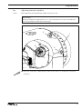
1.05.01
Basic position of the balance wheel (adjustment aid)
Requirement
When the needle bar is positioned at t.d.c., the marking "0" on the scale should be level
with the top edge of the belt guard (see arrow).
2
1
3
2
3
Fig. 1 - 01
● Adjust the scale dial 1 ( depending on model screws 2 or 3 ) in accordance with the requirement.
5
Adjustment
1.05.02
Balance weight
Requirement
When the needle bar is positioned at b.d.c. (balance wheel position 180°) the largest eccentricity of the balance weight 1 should be at the top.
1
2
2
1
Fig. 1 - 02
● Adjust balance weight 1 (screw 2) in accordance with the requirement.
6
Adjustment
1.05.03
Zero position of the unison feed
Requirement
When the stitch length is set at "0", the top and bottom feed dogs and the needle bar
should not make any feeding motion when the balance wheel is turned.
2
1
3
Fig. 1 - 03
● Remove spring 1.
● Adjust crank 2 (screw 3) in accordance with the requirement.
● Replace the spring 1.
7
Adjustment
1.05.04
Feeding motion of the unison feed
Requirement
When the needle bar is positioned at b.d.c. (balance wheel position 180°), and the maximum stitch length is set, the top and bottom feed dogs and the needle bar should not
make any feeding motion when the reverse-feed lever is pressed.
2
1
Fig. 1 - 04
● Adjust eccentric 1 (screws 2) in accordance with the requirement. Make sure that the
cut-out (see arrow) is visible.
8
Adjustment
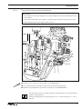
1.05.05
Lifting motion of the bottom feed dog
Requirement
When the balance wheel is positioned at 180°, the feed dog should be at t.d.c.
3
6
5
4
7
2
1
Fig. 1 - 05
● Adjust eccentric 1 (screws 2) in accordance with the requirement.
Use the kit with the Order No. 91-501 398-90 to deactivate the transporter lifting movement.
● Install assembly and adjust
● Remove collar 3 (screws 4) and crank 5 (screw 6, snap-ring 7).
● Mount the preassembled parts of the kit as shown in figures 1 - 05a.
● Adjust bottom transporter height and stroke movement where required.
9
Adjustment
8
10
9
11
8
Fig. 1 - 05a
Activate lifting movement
● Lifting movement is activated if connection part 8 is swiveled in as shon in
figures 1 - 05a, and screws 9 (M6 x 16) and 10 (M5 x 16) have been attached.
Deactivate lifting movement
● Remove screws 9 and 10 and swivel connection part 8 (screw 11) towards the right.
● Replace screw 9 with a screw M6 x 25.
● Replace screw 10 with a threaded pin M5 x 25 and tighten to stop.
Adjust transporter height with deactivated stroke movement so that the upper
edge of the transporte is at the height of the upper edge of the needle plate.
Adjust the transporter height once again with the stroke movement activated,
as described in chapter 1.05.06.
10
Adjustment
Height of the bottom feed dog
Requirement
1. When the stitch length is set at "0" and the needle bar is positioned at b.d.c. (balance
wheel position 180°), the bottom feed dog should be positioned 0.5 mm horizontally
above the top edge of the needle plate.
2. In the direction of sewing, the bottom feed dog should be positioned in the centre of
the needle plate slot.
2
2
1
0,5 mm
1.05.06
3
5
4
Fig. 1 - 06
4
● Turn lifting crank 1 (screws 2) and eccentric sleeve 3 (screws 4) in accordance with
requirement 1.
● Adjust feed bar 5 (screws 4) in accordance with requirement 2.
11
Adjustment
1.05.07
Feeding stroke difference
Requirement
With the maximum stitch length set, when the balance wheel is turned the feeding strokes of the needle and the bottom feed dog should be the same.
1
2
-
+
Fig. 1 - 07
● With connecting rod 1 (nut 2) increase ("+") or reduce (-) the needle feed stroke in
accordance with the requirement.
12
Adjustment
Preliminary adjustment of the needle height
Requirement
When the needle bar is positioned at t.d.c. (balance wheel position 0°), the clearance
between the needle point and the needle plate should be 22 mm.
1
3
22 mm
1.05.08
2
1
Fig. 1 - 08
● Without turning it, re-position needle bar 1 (screw 2) in accordance with the
requirement.
Make sure that needle bar 1 and foot 3 do not collide.
13
Adjustment
1.05.09
Needle rise, hook clearance and needle height
Requirement
With the stitch length set at "4.5" and in the needle rise position (see table)
1. The hook point 5 should be positioned at "needle centre" with a hook-to-needle clearance of 0.05 – 0.10 mm.
2. The top of the needle eye should be positioned 0.8 mm below hook point 5.
Needle rise position
Model C:
Balance wheel position 202° / 2.0 mm
Model C/D: Balance wheel position 204° / 2.4 mm
4
0,05 - 0,10 mm
2
5
3
1
2
0,8 mm
5
Fig. 1 - 09
● Set stitch length "4.5" and bring the balance wheel into the needle rise position.
● Adjust hook 1 (screws 2) in accordance with requirement 1.
● Bring oil distributor ring 3 (screw 4) into contact with hook 1.
● Without turning it, re-position the needle bar in accordance with the requirement 2.
14
Adjustment
Top feed stroke
Requirement
With adjustment wheel 1 set at "5", the top feed dog 7 and presser foot 4 should each
rise by 5.0 mm.
5
6
2
3
5 mm
4
1
7
5 mm
1.05.10
Fig. 1 - 10
● Remove the bottom feed dog and set adjustment wheel 1 at "5".
● Loosen the screws of the needle plate, place the metal gauge over the opening of the
needle plate slot so that both sewing feet can be lowered onto the metal gauge.
● For the preliminary adjustment, adjust crank 2 (screw 3) so that there is a clearance of 5
mm between presser foot 4 and the needle plate.
● Adjust crank 5 (screw 6) so that top feed dog 7 and presser foot 4 have the same stroke.
● Check the adjustment in accordance with the requirement, and correct if necessary.
15
Adjustment
1.05.11
Top-feed lifting motion
Requirement
The top feed dog should just have reached the needle plate when the presser foot lift is
set at 5 mm and the needle descending from above is 2 mm above the needle plate.
1
2 mm
2
Fig. 1 - 11
● Turn eccentric 1 (screw 2) in accordance with the requirement.
16
Adjustment
1.05.12
Adjusting the potentiometer for speed reduction
1.05.12.01
On machines with drive P45 PD2-L and P74 ED-L
● Switch on the machine
● Set the smallest stroke "0".
● Using the stroke adjustment function, call up the smallest stroke (LED off), see the Control Panel Instruction Manual.
● Call up parameter "501" and press key "C+" to save the bottom value.
● Set the inner adjustment wheel at maximum stroke "9".
● Using the stroke adjustment function, call up the largest stroke (LED on), see the Control
Panel Instruction Manual.
● Call up parameter "502" and press key "C+" to save the top value.
The speed is adjusted in accordance with Chapter 3.03 Maximum Speed in
the Instruction Manual.
1.05.12.02
On machines with drive PF 321
● Press "P" on the control panel, while simultaneously switching the machine on.
● Enter the code 3112 via the numbered keys and confirm by pressing "E".
● Select parameter 501 via the numbered keys and confirm by pressing "E".
● Set the smallest stroke "0".
● Using the stroke adjustment function, call up the small stroke (LED off), see instruction
manual.
● Take over the value displayed under parameter 501 by pressing "+".
● Select parameter 502 via the numbered keys.
● Set the largest stroke "0".
● Using the stroke adjustment function, call up the large stroke (LED on).
● Take over the value displayed under parameter 502 by pressing "+".
● Press "P" twice to quit the input level
● The new values are taken over when sewing is started, and these are maintained
evenafter the machine is switched off.
The speed is adjusted in accordance with Chapter 3.03 Maximum Speed
in the instruction manual.
Under parameter 117 the speed at max. stroke adjustment can be reduced
again.
17
Adjustment
1.05.13
Machine drive home position
1.05.13.01
On machines with drive P45 PD2-L
● Switch on the machine.
● When the machine is commissioned, "Pulley" appears on the display.
● Call up the parameter input by pressing the scroll key.
● Press the TE key to switch the function keys to input function (LED in the TE key is
illuminated).
● Press the corresponding +/- keys to select parameter "798" and select the service level
C, see chapter Selecting the User Level in the separate instruction manual for the control
panel.
● Select parameter "800" by pressing the corresponding +/- keys.
● Check whether the value is set at "1" (balance wheel turns towards operator) and alter if
necessary.
● Press the scroll key until "Pulley" appears on the display.
● If the pedal is operated, the control unit carries out a teach-in operation.
● The machine runs at low speed until the teach-in operation is completed.
● This operation cannot be interrupted.
● After the teach-in operation, the "Pulley" disappears from the screen - display returns to
standard.
● Select parameter "700" by pressing the +/- keys.
● Sew one stitch by operating the pedal.
● Turn the balance wheel in the direction of rotation until the needle point, descending
from above, is flush with the top edge of the needle plate.
● Conclude the adjustment of the sewing motor by pressing the scroll key.
1.05.13.02
On machines with drive P74 ED-L
On machines with EcoDrive P74 ED-L it is not necessary to check the basic
position of the machine drive unit.
These machines are equipped with an automatic sewing head recognition
function.
18
Adjustment
1.05.13.03
On machines with drive AB 321
● Press button "P" on the control panel, while simultaneously switching the machine on.
● Enter code 3112 via the numbered keys and confirm by pressing "E".
● Enter parameter 290 via the numbered keys and confirm by pressing "E".
● Select mode 42 by pressing the +/- buttons.
● Press "P" twice to quit the input level.
● The new values are taken over when sewing is started, and these are maintained even
after the machine is switched off.
1.05.13.04
On machines with drive PF 321
● Press button "P" on the control panel, while simultaneously switching the machine on.
● Enter code 3112 via the numbered keys and confirm by pressing "E".
● Enter parameter 290 via the numbered keys and confirm by pressing "E".
● Select mode 00 by pressing the +/- buttons.
● Press "P" twice to quit the input level.
● The new values are taken over when sewing is started, and these are maintained even
after the machine is switched off.
19
Adjustment
1.05.14
Bobbin winder
Requirement
1. When the bobbin winder is engaged, the winding spindle must be driven reliably.
When it is disengaged, friction wheel 3 should not be touching drive wheel 1.
2. When it is switched off, the bobbin winder must click securely into its end position
(knife raised).
1
2
3
Fig. 1 - 12
● Adjust drive wheel 1 (screw 2) in accordance with the requirement.
20
Adjustment
1.05.15
Thread check spring and thread regulator
Requirement
1. The movement of thread regulator 3 must be completed when the needle point enters
the material.
2. When the thread loop is at its largest while being passed around the hook, the check
thread spring 3 should rise slightly from the rest 1.
6
5
4
2
3
1
Fig. 1 - 13
● Position rest 1 (screw 2) in accordance with requirement 1.
● Turn sleeve 4 (screw 2) to adjust the tension of thread check spring 3.
● Position thread regulator 5 (screw 6) in accordance with requirement 2.
For technical reasons it may be necessary to deviate from the indicated spring
stroke or spring tension.
Move thread regulator 5 (screw 6) towards ("+") (= more thread) or ("-") (= less
thread).
21
Adjustment
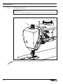
1.05.16
Sewing foot pressure
Requirement
The material should be fed properly even at maximum speed and with the smallest stroke.
1
Fig. 1 - 14
● Turn adjustment wheel 1 in accordance with the requirement.
22
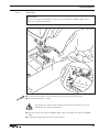
Adjustment
1.05.17
Lubrication
Requirement
After a running time of 10 seconds a thin film of oil should be visible on paper strip 1
when this is held over the hook.
1
2
Fig. 1 - 15
● Check that the machine is filled with oil and that the oil lines are free of air.
● Run the machine for 2 – 3 min.
Do not put your hands into the needle area when the machine is running!
Danger of injury from moving parts!
● With the machine running, hold paper strip 1 against the hook and check the requirement.
● If necessary, regulate amount of oil with screw 2.
23
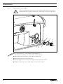
Adjustment
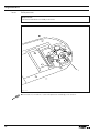
1.05.18
Limiting the stitch length
When exchanging the parts kit with stitch lengths differing from the as-delivered state of the machine, limit the max. stitch length using stitch adjuster 4.
4
7
6
5
Fig. 1 - 16
● Set the desired max. stitch length at control button 1
(on model CN = 6.0 mm, on model CN9 + C/DN9 = 9 mm)
● Remove adjustment knob 1 (screws 2) and scale dial 3.
● Remove adjustment unit 4 (screws 5).
● Bring lineal 6 (screw 7) to the unit using stitch adjuster 4 (see arrow).
● Replace adjustment unit 4, scale dial 3 and adjustment knob 1.
24
3
2
1
Adjustment
1.06
Adjusting the thread trimmer -900/91
1.06.01
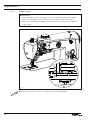
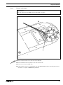
Basic position of the thread trimmer
Requirement
1. When the thread trimmer is in its resting position (cylinder extended), the point of
thread catcher 6 should be flush with the cutting edge of knife 7 (see arrow).
2. The roller lever 3 should have a clearance of 1 mm to the connecting piece.
1 mm
1
5
2
4
2
3
6
7
Fig. 1 - 17
● Adjust thread trimmer 1 (screws 2) in accordance with requirement 1.
● Adjust roller lever 3 (only screw 4) in accordance with requirement 2.
25
Adjustment
1.06.02
Control cam to roller lever clearance (resting position)
Requirement
When the thread trimmer is in its resting position (balance wheel position 270°) there
should be a clearance of 0.1 mm between the roller lever 5 and the outside edge of control cam 1.
2
5
4
3
1
0,1 mm
Fig. 1 - 18
● Adjust control cam 1 (screw 2) together with retaining collar 3 (screw 4) in accordance
with the requirement.
26
Adjustment
1.06.03
Adjusting the control cam
Requirement
When the take-up lever is at the top of its stroke (balance wheel position 70°), the cutting
operation should just have been completed.
1
2
Fig. 1 - 19
● Adjust control cam 1 (screw 2) in accordance with the requirement.
27
Adjustment
1.06.04
Knife pressure
Requirement
The thread should be cut reliably at all times.
+
-
1
Fig. 1 - 20
● Increase ("+") or reduce ("-") the knife pressure accordingly with screw 1.
28
Adjustment
1.06.05
Manual cutting test
Requirement
Both the needle and the bobbin thread should be cut neatly.
1
Fig. 1 - 21
● Bring thread catcher 1 by hand to its front position.
● Take a double thread and place it into the catcher slot.
● Carry out a manual cutting test.
● If the thread is not cut in accordance with the requirement, adjust the knife pressure as
described in Chapter 1.06.04 Knife pressure.
29
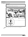
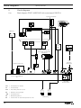
Block diagram
Version 29.03.07
2
Circuit diagrams
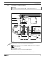
2.01
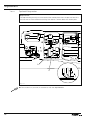
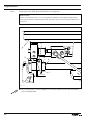
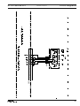
Block diagram PFAFF 2235 PLUS with control pack P45 PD-L
Synchronizer PD 6
Optional
Light
barrier
LED
LED
power
supply
Netzteil
unit
PC
Ministop drive unit
(long) with incremental
transducer
for
software
download
Speed control unit
Control unit QA40 PD
A1
Q1; HQ1
Power switch
FSL
= Thread tension release
FK
= Thread clamp
PFA
= Automatic presser foot lift
ML
= Machine running signal
-900 = Thread trimmer
30
VR
= Backtacking device
KS
= Knee switch for automatic presser foot lift
Mains plug
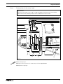
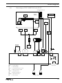
Block diagram
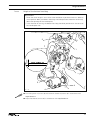
2.02
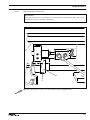
Block diagram PFAFF 2235 PLUS with AB 321
Synchronizer PD 6
PD 6
2235
FSL
BDF
PFA
FK
LS
(Option)
ML
-900
SWG
VR
KS
Adapter
X5
B 80
ST 2
Adapter
1113229
B2
B 41
B 18
B 776
USB
FSL
for Software
download
= Thread tension release
BDF = Control panel
FK
= Thread clamp
PFA
= Automatic presser foot lift
ML
= Machine running signal
-900 = Thread trimmer
VR
= Backtacking device
SWG = Speedcontrolunit
KS
= Knee switch
Mains plug
31
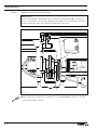
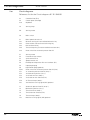
Circuit diagrams
2.03
Version 28.03.07
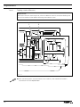
Circuit diagrams
Reference list for the Circuit diagrams 91-191 520-95
32
A1
A2
A16
Controller P45 PD-L
Control panel (PicoTop)
Keyboard
H1
Sewing lamp
M1
Sewing motor
Q1
Main switch
S1
S41
S42
S43
S44
S25
Pedal speed control unit
Reverse sewing or intermediate backtacks key
Raise needle without thread trimming key
Presser foot lift key
Thread clamp key (increase needle thread tension)
Knee switch for automatic presser foot lift
X1
X2
X7
X3
X4
X5
X8
XS25
XY1
XY2
XY3
XY4
XY6
X15
Sewing motor
Incremental transmitter
Synchronizer PD 6
Speed control unit
PicoTop control panel or RS 232 interface (PC)
Input/output plug
Light barrier plug (optional)
Knee switch for automatic presser foot lift (S25)
Y1 automatic presser foot lift (-910/..)
Y2 backtacking device (-911/..)
Y3 thread trimmer (-900/..)
Y4 thread tension release (FSL)
Y5 Thread clamp (-909/..)
Y15 Machine running signal (ML) optional
Y1
Y2
Y3
Y4
Y6
Y15
Automatic presser foot lift (-910/..)
Backtacking device (-911/..)
Thread trimmer (-900/..)
Thread tension release (FSL)
Thread clamp (-909/..)
Machine running signal (ML) optional
91-191 520-95 Part 1
Version 28.03.07
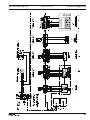
Circuit diagrams
33
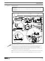
Circuit diagrams
34
Version 28.03.07
91-191 520-95 Part 2
91-191 520-95 Part 3
Version 28.03.07
Circuit diagrams
35
Hans-Geiger-Str. 12 - IG Nord
D-67661 Kaiserslautern
Phone:
Fax:
E-mail:
+49 - 6301 3205 - 0
+49 - 6301 3205 1386
[email protected]
Hotlines:
Technical service:
Application consultance:
Spare-parts hotline:
Printed in Germany
+49 - 175/2243-101
+49 - 175/2243-102
+49 - 175/2243-103
© PFAFF Industriesysteme und Maschinen AG 2009, PFAFF is the exclusive trademark of VSM Group AB.PFAFF Industriesysteme und Maschinen AG is an authorized licensee of the PFAFF trademark.
PFAFF Industriesysteme
und Maschinen AG