1
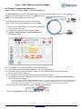
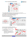
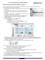
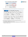
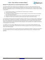
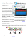
EvSuite – Basic Software User Manual For EvSuite version 1.49 This document provides a basic installation and commissioning instruction for the Batrium Battery TM Angel EvSuite software. It steps through the initial operations required in order to start and connect the EvSuite application. Individual sections are provided to be able to commission particular items depending on the application. It is recommended to set up a single battery PacMon system first (see PacMon section). However, for low level diagnostics (and if a UMon is available), the most basic form of BlockMons/LongMons, IsoMon and UMon hardware (wired up as shown below) can be used, together with the section in the appendix “Basic Commissioning (PC only)”. This manual is broken up into individual sections depending on the application that is being implemented (most common uses PacMon). This manual is not meant to be an exhaustive documentation for the EvSuite software; it provides the initial steps in a more simplified form. It should also be understood that the software is being continually enhanced as new hardware and features are added. This manual particularly applies to EvSuite version 1.49. There are many other more complex features that may only be introduced in this manual. Further details about particular parameters can be found in the individual device data sheets on the web site www.batrium.com. Simple Hardware Installation The following diagram provides the simplest configuration that will allow EvSuite to diagnose and display the status of each of the cells (PcMaster). It is detailed in the appendix of this document. A UMon is required, otherwise use to the PacMon sections of this document. UMon IsoMon NC USB to PC BatteryAngelTM is an international trade mark www.batrium.com © 2010-2014 Ver 1.4 Jan 2014, Page 1 of 16 EvSuite – Basic Software Installation Manual Software Installation Install Version 1.49 or later from the following privileged location:http://www.batrium.com/sw This includes the installation of the USB Drivers. Note: If an earlier version is already installed, then use the Menu: Support => Check for Software Updates. It is recommended that EvSuite/ServiceCentre software is installed on Windows 7 or later with all the latest updates applied. Batrium may not be able to provide detailed support for older operating systems such as Windows XP. It is usually required to also install the Microsoft “Dot Net Framework”. The EvSuite installer will examine your system and prompt you to also install Microsoft “Dot Net Framework” at the appropriate point. This will link you to the web address for the download and install. Installing/Checking the USB Drivers (PacMon or UMon) The software automatically adds the required PacMon/UMon USB drivers for Windows 64 bit or 32 bit systems. Complete the following steps in order to check that the required USB connections are operational before commissioning the system. 1) After installing the software, connect the PC to PacMon/UMon using a USB cable (note that +12V Drive and +12V Charge is OFF). PacMon is connected to the back middle USB connector (labelled: “From System”). UMon is plugged directly into the PC USB port (or using a male-to-female extension cable) Note that +12V is only applied to operate PacMon and it is not applied when configuring PacMon. 2) Check that the USB device(s) are installed OK. It may take a few minutes to install the drivers. The normal USB “acknowledge” sound will be heard from the PC. 3) Once installed the red USB LED(s) will be ON. For PacMon there are two red LEDs (labelled “USB”) inside PacMon. They are visible through the top cover of PacMon. For UMon, the red LED is clearly visible through the plastic cover. 4) If the driver is not automatically installed, it can be manually installed from the:Start Menu => Batrium Pty Ltd => EvSuite => Tools => Driver Installer. 5) The USB devices must be operational (red LEDs) before continuing. 6) It is sometimes necessary to unplug and re-plug the USB device if the connection is lost because of a large power transient or when the USB devices have changed configuration. BatteryAngelTM is an international trade mark www.batrium.com © 2010-20134 Ver 1.4 Jan 2014, Page 2 of 16 EvSuite – Basic Software Installation Manual PacMon Commissioning Sequence (normal PacMon as controller option). The following steps provide the commissioning sequence with a PacMon installed (PC is “Slave”). PacMon is the controller and the TC/Elcon CAN charger is used. PacMon contains an internal SiMon and an internal SiCan (referred to as “PacMon SiMon” and “PacMon SiCan”). 1) Connect PacMon as shown in the PacMon data sheet. In particular the diagram: Application Diagram/Connections - One battery pack and Elcon/TC “CAN” charger. The connection of the external LEDs (and Fuel Door) are optional (as long as the LEDs are visible for the front panel, or internal LEDs are visible). 2) Connect the PC to PacMon using the USB cable (note that +12V Drive and +12V Charge is OFF). Note that +12V is only applied to operate PacMon and it is not applied when configuring PacMon. 3) Once the USB device is installed the two Red LEDs (labelled “USB”) inside PacMon will be ON. They are visible through the top cover of PacMon (see installing drivers above). 4) Run the EvSuite ServiceCentre software from the start menu:Start Menu => Batrium Pty Ltd => EvSuite => ServiceCentre. 5) Select OK for the “No ‘USB Supervisor Host’ was found….” question (with “AutoStart of Host” checked). If not prompted at the start (no UsbHost Settings), locate the Commissioning menu => Host control "Start" button to manually start the UsbHost. It may also be useful to set the AutoStart USB Host options under User Preferences or “Reset” all the preferences to default (always press “Save” after making changes). 6) Use the blue “Previous” button to locate the Commissioning => FindPort (UMon) menu. 7) Follow the sequence 1 through 6 in the diagram above. First Collect (1) to refresh the screen, choose the UMon Serial Names (2) with the left (<) and right (>) arrow buttons. In this PacMon case the UMon Serial Names (2) are (select using the arrows <, >): “PACMON_SIMON” as Ch1 “PACMON_SICAN” as Ch2 8) Enter the First and Last (3) cell number for Ch1 (PACMON_SIMON). The first will always be “1” and the last is the quantity of cells that are in series (number of BlockMons/LongMons in the chain). 9) Remove any previously allocated UMons with the “X” button. Ch7-Chgr must be removed if used previously. 10) Press Send (4) to store the settings, and in most cases it is useful to Stop (5) and Start (6) the Host Control to cause it to refresh the settings. BatteryAngelTM is an international trade mark www.batrium.com © 2010-20134 Ver 1.4 Jan 2014, Page 3 of 16 EvSuite – Basic Software Installation Manual 11) Connect the yellow and blue twisted pair two pin connectors in a daisy chain format (out-to-in, out-to-in). See diagrams in the document “Connecting BlockMon Battery Chain” (from the website). 12) Terminate the last two connections to an IsoMon (4 pin connectors and 2 pin connectors). The extra spare power leads on the IsoMon (red/black) are not needed. They can be cut off or at least insulated (also in the diagram). 13) Connect the IsoMon to the PacMon (using a USB male to female extension cable). Use the “To Battery (IsoMon)” connector on the back of PacMon. 14) Cross-check this set up with the diagrams. 15) Ensure that the +12V connection to PacMon is OFF (PacMon configuration mode). 16) Go to Commissioning menu and press PcSlave. This is because PacMon SiMon will be master. “PcSlave” is always used with PacMon. 17) Set the number sequence in the BlockMons/LongMons using: Commissioning => Node Renumbering menu. 18) Press Send, and observe First ID and Last ID for the number of cells is correct for Channel1. Note that this step also automatically populates values in the FindPort (UMon) settings above (it may be useful to re-check these as well). If the last ID result is 0, then the cell daisy chain network is broken (not continuous). Observe the BlockMon LEDs to locate the break and/or use the Commissioning => Network Tester menu. The Channel2 result does not matter (used for the PacMon SiCan charger channel). 19) Any break in the network must first be located before continuing (Channel1 Last ID result must be correct). Without this the cells numbers cannot be addressed correctly and PacMon will result in critical fault. 20) Set the default “Node Operating Parameters” in the BlockMons/LongMons (cell monitoring units). Use Commissioning => Node Operating Parameters menu. Choose “LiFePO4” defaults. Press “Send”. The values can be checked that they were stored correctly by pressing “Collect”. 21) Still without +12V applied, go to Commission => PacMon SiMon menu. Note this is not the “SiMon Setup” menu option. “PacMon SiMon” menu is available in SW version 1.49 or later. Set Channel ID = 1 (item 1 below). Press Default (2) to set the “normal” parameters for LiFePO4. Set the first and last cell number range parameters (3). Normally first =1 and last = number of cells. Other parameters (4, & 5) are described in the SiMon datasheet. Chose Options (5) tab, and turn OFF the “Requires Upstream SiMon” option. Press Send (6) to send/save them in PacMon SiMon. BatteryAngelTM is an international trade mark www.batrium.com © 2010-20134 Ver 1.4 Jan 2014, Page 4 of 16 EvSuite – Basic Software Installation Manual 22) After “Default” (for LiFePO4 cells), it is usually only required to set the last cell number (3) and the option (5) “Requires Upstream SiMon” to OFF. All other defaults are normally sufficient for LiFePO4. 23) The only time when “Requires Upstream SiMon” is required (set to ON) is when there is a second battery pack (upstream SiMon to PacMon). This setup requires the more advanced use of a second extension SiMon (not covered in this document). 24) The Charging Temperature Control => Critical Relay (RLY1) State (4) option is normally left ON. It is only set to OFF for the more complex case of non-CAN controlled chargers (i.e. only for enabled on/off voltage controlled chargers). When OFF the critical relay (RLY1) will de-energise (open/fail) when an over temperature event occurs. With the CAN chargers (ON) the system will only pause charging until the over temperature has recovered. 25) The operator may wish to later trim the Critical Low Cell Volt alarm threshold and the Warning Low Cell Volt alarm threshold. These are best adjusted after loaded and cell dependant voltages are better understood in the specific application (after significant use). The critical (red) and warning (yellow) voltage threshold alarms are only useful as a last resort to determine if a cell is depleted. The cell voltage is not a predictable indicator of remaining charge for lithium cells (the voltage does not change until depleted). With some carful trimming, the warning alarm threshold can be used to indicate too much current is being taken from the cells (yellow LED) for a specific length of time (typical 3000ms). This is dependent upon the internal resistance of the cells. 26) The correct data can be checked by pressing “Collect” to read all the data from PacMon SiMon. If the data is all “0”, then the battery daisy chain network is broken (discontinuous). 27) The following steps are used to commission the charger options (PacMon SiCan). This is done after setting the parameters for PacMon SiMon (above). 28) Do not apply +12V to PacMon (remain in configuration mode). 29) Check that the “PACMON_SICAN” UMon is allocated to Ch 2 in the Commissioning => Find Ports screen. Remember to press Send. There is no need to allocate any cell numbers (First and Last) for SiCan. 30) Choose Commissioning => PacMon SiCan (see diagram below). This is different to the “SiCan Setup” page (don’t confuse the two pages). 31) Check that the Channel ID = 2 (item 1 above). 32) Press Default (2). 33) The target voltages (3) should be set automatically. The default targets are 3.75V per cell. Note this is approximately 0.1V above the bypass threshold voltage of 3.65V for the cells (default for LiFePO4). If they are not automatically set correctly, these can be manually set: Target Voltage of 3.75V per cell (i.e. for 10 cells use 37.5V) for LiFePO4. High Level Current is the maximum charge current required. Low Level Current is the maximum bypass current. Start at 0.5A for low PCB heating at BlockMon/LongMon. 34) Press “Send” (4) to store the parameters in PacMon SiCan. 35) The correct data can be checked by pressing “Collect” to read all the data from PacMon SiCan. If the data is all “0”, then the data was not stored correctly. BatteryAngelTM is an international trade mark www.batrium.com © 2010-20134 Ver 1.4 Jan 2014, Page 5 of 16 EvSuite – Basic Software Installation Manual Using PacMon “Drive” Mode - PacMon as monitor The following steps provide a basic operating (drive) sequence for PacMon use (also applies to stand alone SiMon). PacMon is the controller and the TC/Elcon CAN charger is used. 1) Complete PacMon Commissioning Sequence (above), and ensure the PacMon wiring is complete. 2) Apply +12V Drive to PacMon (front panel “+12V Drive” and “GND” on the right hand side). 3) The red and yellow LEDs (front of PacMon) will initially be ON at start up (+12V Drive). If the PacMon has been commissioned correctly and the cells are in normal voltage range, the red and yellow LED will go OFF. The green (OK) LED will go ON (see PacMon data sheet for LED details). 4) Also the green LED on the cells (BlockMon/LongMon) will be flashing (in order) at approximately once a second (see BlockMon data sheet for LED details). 5) Go to the Node Chart page and observe the blue bar chart updating. Possible problems: A) Commissioning has not been completed. B) “+12V Drive” is less than 9V. C) Find Port (UMon) is not setup correctly (also try replugging the PC USB port). The top line of the PC should contain text “…. Ch1 OK Ch2 OK ….” D) Cell daisy chain is broken (incomplete). E) Check the red (TX) and green (RX) LED at PacMon connector and on the IsoMon. F) A cell is beyond the operating voltage range. G) Renumbering did not succeed/complete correctly. H) Wrong cell number ranges in Find Port (UMon). I) Wrong cell number ranges in (PacMon SiMon). J) Not in “PcSlave” mode (see Commissioning menu). K) The “USB Supervisor Host” must be running in the PC system tray. There must not be any other PCs on the network with a “USB Supervisor Host” running. 6) Click on the graph to reveal the axis and key. Note the high speed updating Cell Min Voltage, Cell Max Voltage. 7) Go to the User Preferences menu to choose the Node Chart options (auto hide axis, bypass, colours, etc…) and also the Application Options (auto start/auto stop etc…) or Reset all settings to default. Press Save after making changes. 8) Navigate to the Telemetry => SiMon/SiCan Menu. 9) The telemetry response should be populated with the present PacMon SiMon status on Ch1. Initially only Ch1 will be visible. The PacMon SiCan status on Ch2 will only be populated if “+12V Charge” is applied (when charging). 10) Note the flags on the right hand side indicate particular errors that have been detected. 11) Note the Signal In and Signal Out states. This screen allows diagnostics of the PacMon SiMon and PacMon SiCan states (including Signal In and Out connections). 12) Further details about SiMon/SiCan setup parameters are in the SiMon/SiCan datasheet on the Batrium website. BatteryAngelTM is an international trade mark www.batrium.com © 2010-20134 Ver 1.4 Jan 2014, Page 6 of 16 EvSuite – Basic Software Installation Manual Using PacMon “Charge” Mode - PacMon as charger The following steps provide a basic charge sequence for PacMon (also applies to stand alone SiMon and SiCan). PacMon is the controller and the TC/Elcon CAN charger is used. 1) Complete “PacMon Commissioning Sequence” and “PacMon Drive sequence” (above). Ensure the PacMon wiring is complete. 2) The TC/Elcon CAN charger must be connected to PacMon using the CMon cable. It must be mains powered. 3) Apply +12V Charge to PacMon (front panel “+12V Charge” and “GND” on the right hand side). 4) The red, yellow, and blue LEDs (front of PacMon) will initially be ON at start up (+12V Charge). If the PacMon has been commissioned correctly and the cells are in normal voltage range the red and yellow LED will go OFF. The green (OK) LED will go ON (see PacMon data sheet for LED details). 5) The blue charge LED will indicate the PacMon SiCan charge state (see PacMon data sheet for LED details). 6) Also the green LED on the cells (BlockMon/LongMon) will be flashing (in order) at approximately once a second (see BlockMon data sheet). 7) Go to the Node Chart page and observe the blue bar chart updating. If the charger is found, the yellow top right charger readings will also be visible. The second “Bypass” chart will be visible near end of charge (i.e. when bypassing/balancing). Possible problems (in addition to those in the “Drive Mode” list above): A) “Drive Mode” chart was not working first before trying to charge. B) “+12V Charge” is not applied or is less than 9V. C) PacMon SiCan commissioning has not been completed. D) Ch2 UMon is not setup correctly Find Port (UMon). The top line of the PC should contain text “…. Ch1 OK Ch2 OK ….”. Also try re-plugging the PC USB port. E) Not in “PcSlave” mode (see Commissioning menu). F) Charger is not connected (via CMon cable). G) Charger is not powered. 8) To read the PacMon SiCan state, Navigate to the Telemetry => SiMon/SiCan Menu. 9) The telemetry response should be populated with both the present PacMon SiMon status on Ch1 and PacMon SiCan status on Ch2. 10) Note the flags on the right hand side indicate particular errors that have been detected. 11) This screen allows diagnostics of the PacMon SiMon and PacMon SiCan states. 12) SiMon (Ch1) will determine SiCan (Ch2) state through Signal Out and Signal In. SiMon may determine a fault (see Flags) and stop the charge process (SiCan Ch2). First check the Ch1 “Signal Out” state (e.g. “HighPower”), and the Ch1 Flags. 13) Ch2 (SiCan) indicates the “Target Volts and Amp” and the “Actual Volts and Amp”. 14) When the first cell reaches bypass, Ch1 will indicate the number of cells “InBypass” and the “Target Amp” will drop to the “LowPower” setting in PacMon SiCan (Ch2). It may move in and out of HighPower a number of times before stabilising. BatteryAngelTM is an international trade mark www.batrium.com © 2010-20134 Ver 1.4 Jan 2014, Page 7 of 16 EvSuite – Basic Software Installation Manual APPENDIX (for less common configurations) - Advanced Users Only. Basic Commissioning Sequence (PC Only). The following steps provide the most basic commissioning sequence without PacMon or SiMon installed and the PC as “Master”. A UMon must be available. This is useful as a test only (the operator has never used any of Batrium’s products before). This uses the simplest setup as shown in the diagram on the first page. It allows the new operator to become familiar with the simplest setup. The usual system setup is covered in the section about PacMon. 1) Ensure that the EvSuite software has been successfully installed (see above). 2) Connect UMon (red USB device) to the PC and ensure the red LED is ON (see installing USB Drivers above). 3) Initially connect a few batteries to BlockMons (negative to large silver terminal). For LongMons connect a few devices to your cells (via the red and black cables). Once the small 4 pin connector is placed and the positive red wire (also the -ve Black wire for LongMon), the BlockMon/LongMon green LED should stay on (waiting for communications), the red LED will flash once at reset (when power applied). 4) There is no need to connect the batteries in series yet. Be careful not to flex the BlockMon PCB too much when pushing in the small connectors (see BlockMon mechanical details). 5) Connect the yellow and blue twisted pair two pin connectors in a daisy chain format (out-to-in, out-to-in). See diagrams in the document “Connecting XXXXMons Battery Chain” (from the website). 6) Terminate the last two connections to an IsoMon (4 pin connectors and 2 pin connectors). The extra spare power leads on the IsoMon (red and black) are not needed (see basic diagram above). They can be cut off or at least insulated. 7) Connect the IsoMon to the UMon (either using a USB male to female extension cable or directly). 8) Cross-check this set up with the basic installation diagram on the first page. 9) Run the EvSuite ServiceCentre software from the start menu:Start Menu => Batrium Pty Ltd => EvSuite => ServiceCentre. 10) Select OK for the “No ‘USB Supervisor Host’ was….” question (with “AutoStart of Host” checked). If not prompted at the start (with the UsbHost Settings), locate the Commissioning menu => Host control "start" button to manually start the UsbHost. It may also be useful to change the AutoStart USB Host options under User Preferences or simply Reset all the preferences to default (always press “Save” after making changes). 11) Ensure that the UMon (USB device) is plugged (Red LED is ON). 12) Use the blue “Previous” button to locate the Commissioning => FindPort (UMon) menu. BatteryAngelTM is an international trade mark www.batrium.com © 2010-20134 Ver 1.4 Jan 2014, Page 8 of 16 EvSuite – Basic Software Installation Manual 13) Then follow the sequence 1 through 6 in the diagram above. First Collect(1) to refresh the screen, choose the UMon Serial Name(2) with the left (<) and right (>) arrows, enter the First and Last(3) cell for that channel,. If there are no items available under UMon Serial Name choices, then check that the UMon USB device is correctly installed (red LED is on). Check the USB Host is running (see above). There must not be more than one USB host running on your network. You may also need to install the Windows 64bit patch from the install website. Also see the diagnostic guides in the UMon Datasheet. 14) It is important to remove any previously allocated UMons with the “X” button. 15) Press Send(4) to store the settings, and in most cases it is useful to Stop(5) and Start(6) the Host Control to cause it to refresh the settings 16) Select “Previous” for the Commissioning Menu Options and change the System Mode to PcMaster. 17) Check that the top menu bar indicates "Ch1:OK" - EvSuite xxxxxxxx Ch1:OK xxxxxxxx 18) Allocate numbers for your batteries (Commissioning => Node Renumbering). 19) Press Send, and observe First ID and Last ID for the number of cells. Note that this step also automatically populates values in the FindPort (UMon) settings above. Set “1” for the first and the number of cells for the last. 20) Go to the Node Chart page and observe the blue bar chart updating. 21) Click on the graph to reveal the Axis and Key. 22) Note the high speed updating Cell Min Voltage, Cell Max Voltage. 23) Go to the User Preferences menu to select the graphing options (auto hide, colours, etc…) and also the Application Options (auto start/auto stop etc…) or simply Reset all settings to default. Prese Save after making changes. BatteryAngelTM is an international trade mark www.batrium.com © 2010-20134 Ver 1.4 Jan 2014, Page 9 of 16 EvSuite – Basic Software Installation Manual PC Charger Commissioning Sequence (not relevant to PacMon, SiMon, or SiCan installations). The PC charger option is used when the system does not contain a PacMon, SiMon, or SiCan. In this case the PC is master and Elcon/TC charger is connected via a CMon cable and UMon. It is not normally the recommended option. The following steps provide the most basic commissioning sequence with a PC charger installed and the PC as “Master”. 1) Ensure that the basic software commissioning sequence has been completed (see above). 2) Connect the charger via the CMon cable and UMon. 3) Access the Commissioning => FindPort (UMon) menu (See diagram below). 4) 5) 6) 7) 8) 9) Press Collect (1) to refresh the settings from the USB UMon host. Check the cell number range (First and Last) for Ch1 in the diagram above. Choose the UMon (2) that is connected to CMon (Elcon/TC Charger) using the left and right arrows. Enter the total number of Nodes (3). It is important to remove any previously allocated UMons with the “X” button. Press Send (4) to store the settings and in most cases it is useful to Stop (5) and Start (6) the Host Control to cause it to refresh the settings. If there are no items available under UMon Serial Name choices, then check that the UMon USB device is correctly installed (red LED is on). Check the USB Host is running (see above). There must not be more than one USB host running on your network. You may also need to install the Windows 64bit patch from the install website. Also, see the diagnostic guides in the UMon Datasheet. 10) Check that the Windows status bar shows “…Ch7:OK” as shown below. 11) Go to the Commission => PC Charging Setup menu. BatteryAngelTM is an international trade mark www.batrium.com © 2010-20134 Ver 1.4 Jan 2014, Page 10 of 16 EvSuite – Basic Software Installation Manual 12) Choose Collect or Default (1) (depending if the system was previously setup or it is a new system). The default parameters are normally sufficient for most charging conditions and should be used for first-time users. 13) Choose Stage 4 (2) tab “Equalise stage (CV) at least one cell in bypass”. 14) Enter the number of cells in your battery at Nodes in Bypass (3). 15) Press Send (4) to save the data to the host. 16) Apply mains power to the charger connected to the CMon cable. 17) Navigate Home => PC Charging Control Menu. 18) Check that the status indicates Paused (1 - diagram above). 19) Check that the charger is reading the actual total battery Voltage (2). 20) Turn the AutoMode (3) to ON to start the charger. 21) The Charging Stages (2) and Status (3) will change (see diagram on the right). 22) The Target Voltage and Current (4) will be shown. If the target voltage is 0V, then it is likely that the Commissioning => FindPort (UMon) number of cells at Ch7 has not been assigned. See step ”3)” at the beginning of this chapter. BatteryAngelTM is an international trade mark www.batrium.com © 2010-20134 Ver 1.4 Jan 2014, Page 11 of 16 EvSuite – Basic Software Installation Manual 23) Navigate to the Node Chart to observe the charging process. If the blue bargraph data is not updating check the Commissioning => FindPort (UMon) number of cells allocated at Ch1. See step “3)” at the beginning of this chapter. Also check that the PC is set to “Master”. 24) Once charge is complete the value shown at “Actual Charger A” will show 0A. 25) The charger can be set to AutoStart when the software is started in the “PC Charging Setup” menu by changing the switch to ON at Stage 1. Remember to Press “Send”. BatteryAngelTM is an international trade mark www.batrium.com © 2010-20134 Ver 1.4 Jan 2014, Page 12 of 16 EvSuite – Basic Software Installation Manual SiMon Commissioning Sequence (SiMon standalone). The following steps provide the most basic commissioning sequence with a SiMon installed and the PC as “Slave”. Do not use this sequence for PacMon installations. 1) Ensure that the basic software commissioning sequence has been complete (see above). 2) Connect SiMon to SiLed PCB or wire it manually to the dash LEDs etc… 3) Place SiMon in-between UMon and IsoMon (see SiMon Datasheet for diagrams). 4) Do not apply +12V to SiMon (it is initially powered by the USB +5V) to allow configuration with SiMon Slave and PC Master. 5) The UMon must have first been selected using the Commissioning => FindPort (UMon) menu (see Basic Commissioning Sequence). 6) Without +12V applied:go to Commission menu and the SiMon SetUp Set Channel ID = 1 (item 1 below). Press Default (2) to show a set of normal parameters. Set the parameters (3, 4, & 5) as described in the SiMon Datasheet. Press Send (6) to save them in SiMon. 7) Each parameter is detailed in the SiMon Datasheet. However note that the Charging Temperature Control => Critic Relay (RLY1) State (4) option must only be set to OFF for the more difficult case of non-CAN controlled chargers (i.e. enabled on/off voltage controlled chargers). 8) Go to Commissioning menu and press PcSlave. This is because SiMon will be master. 9) If a SiLed PCB is available (SiLed has all the interface wiring and LEDs included): Connect a SiLed PCB to the SiMon 8 pin (white) connector. Apply power to the +12V Drive pin and GND on SiLed. 10) If SiMon is manually wired (not using a SiLed PCB): Wire up the green, yellow, and red LEDs as per the SiMon Datasheet (for your application). Apply +12V between the red and black wires on SiMon. Connect the white SigIn wire to +12V. 11) The green LEDs on the BlockMons/LongMons and IsoMon will start to flash. Also observe the LEDs on SiMon and IsoMon (both IsoMon green Transmit LED and the red Receive LED will flash). 12) Go to the Node Chart and observe the blue bargraph updating. 13) Remember to remove the +12V (+12V Drive) when changing the SiMon parameters. BatteryAngelTM is an international trade mark www.batrium.com © 2010-20134 Ver 1.4 Jan 2014, Page 13 of 16 EvSuite – Basic Software Installation Manual SiCan Commissioning Sequence (SiMon/SiCan Standalone) (only applies to CAN-enabled Chargers). The following steps provide the most basic commissioning sequence with a SiMon and SiCan installed and the PC as “Slave”. Note that this sequence does not apply to enable on/off or voltage controlled chargers without a SiCan. Do not use this sequence for PacMon installations. 1) Ensure that the basic software commissioning sequence has been completed (see above). 2) Ensure that the SiMon commissioning sequence has been completed (see above). 3) Connect SiCan to SiLed PCB or wire it manually to the blue LEDs etc… 4) Place SiCan in-between UMon and CMon (connected to the CAN enabled charger). See SiMon Datasheet for diagrams. 5) Do not apply +12V to SiMon (it is powered off USB +5V) to allow configuration. 6) For non-SiLed installations (with manual wiring), connect the green SigOut wire from SiMon to the white wire SigIn at SiCan (see SiCan Datasheet application diagrams). The green SigOut wire from SiCan is not connected. 7) Allocate the SiCan UMon to Ch 2 in the Commissioning - Find Ports screen. Remember to press Send. There is no need to allocate any cell numbers (First and Last) for SiCan. 8) Check that the PC is set to PcSlave under Commissioning => System Mode (see diagram on the right). 9) Choose Commissioning - SiCan Setup (see diagram below). 10) Check that the Channel ID = 2 is selected (item 1 above). 11) Press Default (2). The target voltages (3) should be set automatically. The default targets are 3.75V per cell. Note this is approximately 0.1V above the end (bypass) threshold voltage of 3.65V (default). If they are not set automatically then check the Node Renumbering. Also check the Find Port (UMon) => First and Last cell number allocations and set them manually. See details at steps in the Basic Commissioning Sequence in the section above. 12) Press Send. 13) Apply +12V Charge to SiLed and GND (or directly to SiMon and SiCan if manually wired) to begin the charge sequence. 14) Observe the node chart bargraph. 15) Navigate to the Telemetry => SiMon/SiCan Menu. BatteryAngelTM is an international trade mark www.batrium.com © 2010-20134 Ver 1.4 Jan 2014, Page 14 of 16 EvSuite – Basic Software Installation Manual 16) The telemetry response should be populated with both SiMon status on Ch1 and SiCan status on Ch2. 17) Note the flags on the right hand side indicate particular errors that have been detected. 18) Note the Signal In and Signal Out states. This screen allows diagnostics of the PacMon SiMon and PacMon SiCan states (including Signal In and Out connections). 19) Further details about SiCan setup parameters and particular debugging sequences are detailed in the SiCan Datasheet on the Batrium website. BatteryAngelTM is an international trade mark www.batrium.com © 2010-20134 Ver 1.4 Jan 2014, Page 15 of 16 EvSuite – Basic Software Installation Manual Multiple PCs (ServiceCentre) connected by Ethernet or WiFi. The EvSuite software allows multiple ServiceCentre applications to be run at once. Each additional ServiceCentre application running is able to monitor and display the bargraph for the battery system that is connected via the PC with the UMon host application running on it. This means that you can use a second computer to remotely monitor the status of your system. 1) Install the EvSuite software on a second PC that is connected via Wi-Fi or Ethernet. 2) Run the ServiceCentre software. 3) If prompted, do not start the second host on the remote computer. The host must be running on the computer that is connected to the batteries. 4) Observe the window bar at the top of the screen. It should indicate that the appropriate channels are “OK”. 5) Navigate to the node chart and observe the same screen that is visible on the remote computer. It is important to understand some of the background methods to achieve this, as it is possible to create a situation that will no longer allow your batteries to be monitored. The computer that is connected to the batteries has the USB UMon host running. This application transmits (broadcasts) all the information about your system over the Ethernet (Wi-Fi) network. The ServiceCentre actually just listens to these messages. Thus it is possible to have multiple ServiceCentres running anywhere on your network. The problem occurs when multiple USB UMon hosts are running on the same network. Each USB UMon host will transmit resulting in conflicting data. In this situation the data will be corrupted. In order to proceed, the second USB Host must be closed (stopped). The use of a remote ServiceCentre is a powerful option once it is mastered by the operator. It opens many new options for operators. Batrium will soon be releasing further significant enhancements to the “Wi-Fi” linked electric vehicle application. BatteryAngelTM is an international trade mark www.batrium.com © 2010-20134 Ver 1.4 Jan 2014, Page 16 of 16