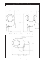
1
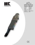
DiamondBack ™
Orbital Weldhead
Owner’s Manual
Product:
DiamondBack
Manual:
091-0511
Serial:
02100001
Voltage Rating: N/A
Revision:
June 2009 Rev C
Model Number: 5006
Table of Contents
Safety Guidelines..............................................................................i - iii
Installation................................................................................ Section A
Technical Specifications............................................................................................................... 1
Electrical................................................................................................................................ 1
Mechanical............................................................................................................................ 1
Weldhead Connections................................................................................................................ 1
Collet Selection & Adjustment...................................................................................................... 2
Tungsten Electrode Properties..................................................................................................... 2
Gas Flow Rates........................................................................................................................... 4
Operations................................................................................Section B
Weldhead Calibration................................................................................................................... 5
Accessories..............................................................................Section C
Benchmount................................................................................................................................. 5
Extension Cable........................................................................................................................... 5
Collets.......................................................................................................................................... 6
Maintenance.............................................................................Section D
Preventative Maintenance........................................................................................................... 6
Rotor Accuracy............................................................................................................................. 6
Cable Assembly........................................................................................................................... 6
Troubleshooting........................................................................Section E
Arc Start Troubleshooting............................................................................................................ 7
Operational Troubleshooting........................................................................................................ 7
Appendices...............................................................................Section F
Diagram/Parts List....................................................................................................................... 9
Appendix A: Collets.................................................................................................................... 15
Appendix B: Pre-Ground Tungsten Electrodes.......................................................................... 15
Appendix C: Overall Dimenisonal Drawings.............................................................................. 16
Warranty
Declaration of Conformity for
European Community (CE) Products
Note
This information is provided for units with CE certification (see rating label on unit).
Manufacturer’s Name:
MK Products, Inc.
16882 Armstrong Ave.
Irvine, CA 92606
Declares that the product:
DiamondBack
™
conforms to the following Directives and Standards:
Directives
Low Voltage Directive: 73/23/EEC
Electromagnetic Compatibility (EMC) Directive: 89/336/EEC
Standards
Arc Welding Equipment Part I: Welding Power Sources: IEC 60974-1
(September 1998 - Second Edition)
Arc Welding Equipment: Wirefeed Systems: IEC 974-5
(September 1997 - Draft Revision)
Degrees of Protection Provided by Enclosures (IP Code): IEC 529:1989
(November 1989 - First Edition)
Insulation Coordination For Equipment With Low-Voltage Systems:
Part I: Principles, Requirements and Tests: IEC 664-1: 1992
(October 1992 - First Edition)
Electromagnetic Compatibility, (EMC): EN 50199
(August 1995)
Torches And Guns For Arc Welding, EN 50078
SAFETY CONSIDERATIONS
ELECTRIC ARC WELDING EQUIPMENT
CAUTION : READ BEFORE ATTEMPTING INSTALLATION, OPERATION
OR MAINTENANCE OF THIS EQUIPMENT
1-1 INTRODUCTION
This equipment is intended for ultimate
application by commercial/industrial
users and for operation by persons
trained and experienced in the use and
maintenance of welding equipment.
Operation should not be undertaken
without adequate training in the use of
such equipment. Training is available
from many public and private schools or
similar facilities.
Safe practices in the installation,
operation and maintenance of this
equipment requires proper training in
the art, a careful study of the information
provided with the equipment, and the
use of common sense. Rules for safe
use are generally provided by suppliers
of welding power sources, compressed
gas suppliers, and electrode suppliers.
Careful compliance with these rules will
promote safe use of this equipment.
The following Safety Rules cover some
of the more generally found situations.
READ THEM CAREFULLY. In case of
any doubt, obtain qualified help before
proceeding.
1-2 GENERAL PRECAUTIONS
A. Burn Prevention
ELECTRIC ARC WELDING PRODUCES
H I G H I N T E N S I T Y H E AT A N D
ULTRAVIOLET RADIANT ENERGY
WHICH MAY CAUSE SERIOUS AND
PERMANENT EYE DAMAGE AND
WHICH MAY DAMAGE ANY EXPOSED
SKIN AREAS.
Wear helmet with safety goggles or
glasses with side shields underneath,
appropriate filter lenses or plates
(protected by clear cover glass). This is a
must for welding or cutting (and chipping)
to protect the eyes from radiant energy
and flying metal. Replace cover glass
when broken, pitted, or spattered.
Medical first aid and eye treatment.
First aid facilities and a qualified first aid
person should be available for each shift
unless medical facilities are close by for
immediate treatment of flash burns of the
eyes and skin burns.
Wear protective clothing - leather (or
asbestos) gauntlet gloves, hat, and high
safety-toe shoes. Button shirt collar and
pocket flaps, and wear cuffless trousers
to avoid entry of sparks and slag.
Avoid oily or greasy clothing. A spark
may ignite them.
Flammable hair preparations should not
be used by persons intending to weld
or cut.
Hot metal such as electrode stubs and work
pieces should never be handled without
gloves.
Ear plugs should be worn when working
on overhead or in a confined space. A
hard hat should be worn when others work
overhead.
B. Toxic Fume Prevention
WARNING: The use of this product may
result in exposure to chemicals known to
the State of California to cause cancer and
birth defects or other reproductive harm.
Adequate ventilation. Severe discomfort,
illness or death can result from fumes,
vapors, heat, or oxygen enrichment or
depletion that welding (or cutting) may
produce. Prevent them with adequate
ventilation. NEVER ventilate with oxygen.
C. Fire and Explosion Prevention
Causes of fire and explosion are:
combustibles reached by the arc,
flame, flying sparks, hot slag, or heated
material, misuse of compressed gases
and cylinders, and short circuits.
BE AWARE THAT flying sparks or falling
slag can pass through cracks, along
pipes, through windows or doors, and
through wall or floor openings, out of
sight of the goggled operator. Sparks
can fly many feet.
To prevent fires and explosion:
Keep equipment clean and operable,
free of oil, grease, and (in electrical parts)
of metallic particles that can cause short
circuits.
Lead-, cadmium-, zinc-, mercury-, berylliumbearing and similar materials, when welded
or cut, may produce harmful concentrations
of toxic fumes. Adequate local exhaust
ventilation must be used, or each person in
the area, as well as the operator, must wear
an air-supplied respirator. For beryllium,
both must be used.
If combustibles are in area, do NOT weld
or cut. Move the work if practicable, to
an area free of combustibles. Avoid paint
spray rooms, dip tanks, storage areas,
ventilators. If the work cannot be moved,
move combustibles at least 35 feet away,
out of reach of sparks and heat; or protect
against ignition with suitable and snugfitting, fire-resistant covers or shields.
Metals coated with or containing materials
that emit toxic fumes should not be heated
unless coating is removed form the work
surface, the area is well ventilated, or the
operator wears an air-supplied respirator.
Walls touching combustibles on opposite
sides should not be welded on (or cut).
Walls, ceilings, and floor near work
should be protected by heat-resistant
covers or shields.
Work in a confined space only while it is
being ventilated and, if necessary, while
wearing an air-supplied respirator.
Fire watcher must be standing by with
suitable fire extinguishing equipment
during and for some time after welding
or cutting if:
Gas leaks in a confined space should be
avoided. Leaked gas in large quantities can
change oxygen concentration dangerously.
Do not bring gas cylinders into a confined
space.
Leaving confined space, shut OFF gas
supply at source to prevent possible
accumulation of gases in the space if
downstream valves have been accidentally
opened or left open. Check to be sure that
the space is safe before reentering it.
Vapors from chlorinated solvents can
be decomposed by the heat of the
arc (or flame) to form PHOSGENE, a
highly toxic gas, and other lung and eye
irritating products. The ultraviolet (radiant)
energy of the arc can also decompose
trichloroethylene and perchloroethylene
vapors to form phosgene. DO NOT
WELD or cut where solvent vapors can
be drawn into the welding or cutting
atmosphere or where the radiant energy
can penetrate to atmospheres containing
even minute amounts of trichloroethylene
or perchloroethylene.
DiamondBack™ Owner’s Manual - Page i
1.Appreciable combustibles (including
building construction) are within 35 feet.
2.Appreciable combustibles are further
than 35 feet, but can be ignited by sparks.
3.Openings (concealed or visible) in
floors or walls within 35 feet may expose
combustibles to sparks.
4.Combustibles adjacent to walls,
ceilings, roofs, or metal partitions can be
ignited by radiant or conducted heat.
Hot work permit should be obtained
before operation to ensure supervisor’s
approval that adequate precautions have
been taken.
After work is done, check that area is free
of sparks, glowing embers, and flames.
An empty container that held
combustibles, or that can produce
flammable or toxic vapors when heated,
must never be welded on or cut, unless
container has first been cleaned in
accordance with industry standards.
This includes: a thorough steam or
caustic cleaning (or a solvent of water
washing, depending on the combustible’s
solubility), followed by purging and
inerting with nitrogen or carbon dioxide,
and using protective equipment.
Water-filling just below working level may
substitute for inerting.
A container with unknown contents
should be cleaned (see paragraph
above). Do NOT depend on sense of
smell or sight to determine if it is safe to
weld or cut.
Hollow castings or containers must be
vented before welding or cutting. They
can explode.
Explosive atmospheres. NEVER weld or
cut where the air may contain flammable
dust, gas, or liquid vapors (such as
gasoline).
D. Compressed Gas Equipment
The safe handling of compressed gas
equipment is detailed in numerous
industry publications. The following
general rules cover many of the most
common situations.
1. Pressure Regulators
Regulator relief valve is designed
to protect only the regulator from
overpressure; it is not intended to protect
any downstream equipment. Provide
such protection with one or more relief
devices.
illegal and hazardous.
Empties: Keep valves closed, replace caps
securely; mark MT; keep them separate
from FULLS, and return promptly.
Prohibited use. Never use a cylinder or its
contents for other than its intended use,
NEVER as a support or roller.
Locate or secure cylinders so they cannot
be knocked over.
Passageways and work areas. Keep
cylinders clear of areas where they may
be stuck.
Transporting cylinders. With a crane, use
a secure support such as a platform or
cradle. Do NOT lift cylinders off the ground
by their valves or caps, or by chains, slings,
or magnets.
Do NOT expose cylinders to excessive
heat, sparks, slag, and flame, etc. that may
cause rupture. Do not allow contents to
exceed 55° C (130° F.) Cool with water
spray where such exposure exists.
Protect cylinders, particularly valves from
bumps, falls, falling objects, and weather.
Replace caps securely when moving
cylinders.
Stuck valve. Do NOT use a hammer
or wrench to open a cylinder valve that
cannot be opened by hand. Notify your
supplier.
sources of ignition. Wipe with a clean,
lintless cloth.
Match regulator to cylinder. Before
connecting, check that the regulator label
and cylinder marking agree, and that the
regulator inlet and cylinder outlet match.
NEVER Connect a regulator designed
for a particular gas or gases to a cylinder
containing any other gas.
Tighten connections. When assembling
threaded connections, clean and smooth
seats where necessary. Tighten. If
connection leaks, disassemble, clean,
and retighten, using properly fitting
wrench.
Adapters. Use a CGA adapter (available
from your supplier) between cylinder
and regulator, if one is required. Use
two wrenches to tighten adapter marked
RIGHT and LEFT HAND threads.
Regulator outlet (or hose) connections
may be identified by right hand threads
for oxygen and left hand threads (with
grooved hex on nut or shank) for fuel gas.
5. Pressurizing Steps:
Drain regulator of residual gas through
suitable vent before opening cylinder
(or manifold valve) by turning adjusting
screw in (clockwise). Draining prevents
excessive compression heat at high
pressure seat by allowing seat to open
on pressurization. Leave adjusting
screw engaged slightly on single-stage
regulators.
Never connect a regulator to a cylinder
containing gas other than that for which
the regulator was designed.
Mixing gases. NEVER try to mix any gases
in a cylinder.
Remove faulty regulator from service
immediately for repair (first close cylinder
valve). The following symptoms indicate
a faulty regulator:
Cylinder fittings should never be modified
or exchanged.
Stand to side of regulator while opening
cylinder valve.
Excessive Creep - if delivery pressure
continues to rise with downstream valve
closed.
3. Hose
Prohibited use. Never use hose other
than that designed for the specified gas.
A general hose identification rule is: red
for fuel gas, green for oxygen, and black
for inert gases.
Faulty Gauge - if gauge pointer does not
move off stop pin when pressurized, nor
returns to stop pin after pressure release.
Use ferrules or clamps designed for the
hose (not ordinary wire or other substitute)
as a binding to connect hoses to fittings.
Open cylinder valve slowly so that
regulator pressure increases slowly.
When gauge is pressurized (gauge
reaches regulator maximum) leave
cylinder valve in following position: for
oxygen and inert gases, open fully to
seal stem against possible leak; for fuel
gas, open to less than one turn to permit
quick emergency shut-off.
Repair. Do NOT attempt repair.
Send faulty regulators for repair to
manufacturer’s designated repair center,
where special techniques and tools are
used by trained personnel.
No copper tubing splices. Use only
standard brass fittings to splice hose.
Leaks - if gas leaks externally.
2. Cylinders
Cylinders must be handled carefully to
prevent leaks and damage to their walls,
valves, or safety devices:
Avoid electrical circuit contact with
cylinders including third rails, electrical
wires, or welding circuits. They can
produced short circuit arcs that may lead
to a serious accident. (See 1-3C)
ICC or DOT marking must be on each
cylinder. It is an assurance of safety
when the cylinder is properly handled.
Identifying gas content. Use only
cylinders with name of gas marked on
them; do not rely on color to identify gas
content. Notify supplier if unmarked.
NEVER DEFACE or alter name, number,
or other markings on a cylinder. It is
NEVER refill any cylinder.
Avoid long runs to prevent kinks and
abuse. Suspend hose off ground to keep
it from being run over, stepped on, or
otherwise damaged.
Coil excess hose to prevent kinks and
tangles.
Protect hose from damage by sharp
edges, and by sparks, slag, and open
flame.
Examine hose regularly for leaks,
wear, and loose connections. Immerse
pressured hose in water; bubbles indicate
leaks
Repair leaky or worn hose by cutting area
out and splicing. Do NOT use tape.
4. Proper Connections
Clean cylinder valve outlet of impurities
that may clog orifices and damage seats
before connecting regulator. Except
for hydrogen, crack valve momentarily,
pointing outlet away from people and
DiamondBack™ Owner’s Manual - Page ii
Use pressure charts (available from
your supplier) for safe and efficient
recommended pressure settings on
regulators.
Check for leaks on first pressurization
and regularly thereafter. Brush with soap
solution. Bubbles indicate leaks. Clean
off soapy water after test; dried soap is
combustible.
E. User Responsibilities
Follow all Safety Rules.
Remove leaky or defective equipment
from service immediately for repair. Read
and follow user manual instructions.
F. Leaving Equipment Unattended
Close gas supply at source and drain
gas.
G. Rope Staging-Support
Rope staging-support should not be
used for welding or cutting operation;
rope may burn.
1-3 ARC WELDING
Comply with precautions in 1-1, 1-2, and
this section. Arc Welding, properly done,
is a safe process, but a careless operator
invites trouble. The equipment carries
high currents at significant voltages.
The arc is very bright and hot. Sparks
fly, fumes rise, ultraviolet and infrared
energy radiates, weldments are hot,
and compressed gases may be used.
The wise operator avoids unnecessary
risks and protects himself and others
from accidents.
A. Burn Protection
Comply with precautions in 1-2.
The welding arc is intense and visibly
bright. Its radiation can damage eyes,
penetrate lightweight clothing, reflect
from light-colored surfaces, and burn
the skin and eyes. Skin burns resemble
acute sunburn; those from gas-shielded
arcs are more severe and painful.
DON’T GET BURNED; COMPLY WITH
PRECAUTIONS.
1. Protective Clothing
Wear long-sleeve clothing in addition to
gloves, hat, and shoes. As necessary,
use additional protective clothing such
as leather jacket or sleeves, flameproof
apron, and fire-resistant leggings. Avoid
outer garments of untreated cotton.
Bare skin protection. Wear dark,
substantial clothing. Button collar to
protect chest and neck, and button
pockets to prevent entry of sparks.
2. Eye and Head Protection
Protect eyes from exposure to arc. Eyes
may be damaged by radiant energy
when exposed to the electric arc, even
when not looking in the direction of the
arc. Never look at an electric arc without
protection.
Welding helmet or shield containing a
filter plate shade no. 12 or denser must
be used when welding. Place over face
before striking arc.
Protect filter plate with a clear cover plate.
Cracked or broken helmet or shield
should NOT be worn; radiation can be
passed through to cause burns.
Cracked, broken, or loose filter plates
must be replaced IMMEDIATELY.
Replace clear cover plate when broken,
pitted, or spattered.
Flash goggles with side shields MUST
be worn under the helmet to give some
protection to the eyes should the helmet
not be lowered over the face before an arc
is struck. Looking at an arc momentarily
with unprotected eyes (particularly a high
intensity gas-shielded arc) can cause a
retinal burn that may leave a permanent
dark area in the field of vision.
3. Protection of Nearby Personnel
Enclose the welding area. For production
welding, a separate room or enclosed
bay is best. In open areas, surround
the operation with low-reflective,
noncombustible screens or panels.
Allow for free air circulation, particularly
at floor level.
Viewing the weld. Provide face shields
for all persons who will be looking directly
at the weld.
at connections.
Others working in area. See that all
persons are wearing flash goggles.
If a line cord with a ground lead is provided
with the equipment for connection to a
switch box, connect the ground lead to
the grounded switch box. If a threeprong plug is added for connection to a
grounded mating receptacle, the ground
lead must be connected to the ground
prong only. If the line cord comes with a
three-prong plug, connect to a grounded
mating receptacle. Never remove the
ground prong from a plug, or use a plug
with a broken ground prong.
Before starting to weld, make sure that
screen flaps or bay doors are closed.
B. Toxic Fume Prevention
Comply with precautions in 1-2B.
Generator engine exhaust must be
vented to the outside air. Carbon
monoxide can kill.
C. Fire and Explosion Prevention
Comply with precautions in 1-2C.
Equipment’s rated capacity. Do not
overload arc welding equipment. It may
overheat cables and cause a fire.
Loose cable connections may overheat
or flash and cause afire.
Never strike an arc on a cylinder or
other pressure vessel. It creates a brittle
area that can cause a violent rupture or
lead to such a rupture later under rough
handling.
D. Compressed Gas Equipment
Comply with precautions in 1-2D.
E. Shock Prevention
Exposed electrically hot conductors or
other bare metal in the welding circuit,
or in ungrounded, electrically-HOT
equipment can fatally shock a person
whose body becomes a conductor. DO
NOT STAND, SIT, LIE, LEAN ON, OR
TOUCH a wet surface when welding
without suitable protection.
To protect against shock:
Keep body and clothing dry. Never
work in damp area without adequate
insulation against electrical shock. Stay
on a dry duckboard, or rubber mat when
dampness or sweat cannot be avoided.
Sweat, sea water, or moisture between
body and an electrically HOT part - or
grounded metal - reduces the body
surface electrical resistance, enabling
dangerous and possibly lethal currents
to flow through the body.
1. Grounding the Equipment
When installing, connect the frames of
each unit such as welding power source,
control, work table, and water circulator
to the building ground. Conductors must
be adequate to carry ground currents
safely. Equipment made electrically HOT
by stray currents may shock, possibly
fatally. Do NOT GROUND to electrical
conduit, or to a pipe carrying ANY gas
or a flammable liquid such as oil or fuel.
Three-phase connection. Check phase
requirement of equipment before
installing. If only three-phase power
is available, connect single-phase
equipment to only two wires of the
three-phase line. Do NOT connect
the equipment ground lead to the third
(live) wire, or the equipment will become
electrically HOT - a dangerous condition
that can shock, possibly fatally.
Before welding, check ground for
continuity. Be sure conductors are
touching bare metal of equipment frames
DiamondBack™ Owner’s Manual - Page iii
2. Connectors
Fully insulated lock-type connectors
should be used to join welding cable
lengths.
3. Cables
Frequently inspect cables for wear,
cracks, and damage. IMMEDIATELY
REPLACE those with excessively worn
or damaged insulation to avoid possibly
lethal shock from bared cable. Cables
with damaged areas may be taped to give
resistance equivalent to original cable.
Keep cable dry, free of oil and grease,
and protected from hot metal and sparks.
4. Terminals and Other Exposed
Parts
Terminals and other exposed parts of
electrical units should have insulating
covers secured before operation.
5. Electrode Wire
Electrode wire becomes electrically
HOT when the power switch of gas
metal-arc welding equipment is ON
and welding gun trigger is pressed.
Keep hands and body clear of wire
and other HOT parts.
6. Safety Devices
Safety devices such as interlocks
and circuit breakers should not be
disconnected or shunted out.
Before installation, inspection, or service
of equipment, shut OFF all power, and
remove line fuses (or lock or red-tag
switches) to prevent accidental turning
ON of power. Disconnect all cables from
welding power source, and pull all 115
volts line-cord plugs.
Do not open power circuit or change
polarity while welding. If, in an emergency,
it must be disconnected, guard against
shock burns or flash from switch arcing.
Leaving equipment unattended. Always
shut OFF, and disconnect all power to
equipment.
Power disconnect switch must be
available near the welding power source.
Thank You
For selecting a quality product. We want you to take
pride in operating this product...as much pride as we
have in bringing the product to you!
Please Examine Carton and Equipment For Damage Immediately
When this equipment is shipped, title passes to the purchaser upon receipt by the
carrier. Consequently, claims for material damaged in shipment must be made by the
purchaser against the transportation company at the time the shipment is received.
Please record your equipment identification information below for future reference. This
information can be found on your machine nameplate.
Model Name & Number
_____________________
Code & Serial Number
_____________________
Date of Purchase
_____________________
Whenever you request replacements parts for, or information on this equipment always
supply the information you have recorded above.
Read this Owner’s Manual completely before attempting to use this equipment. Save this manual
and keep it handy for quick reference. Pay particular attention to the safety instructions we
have provided for your protection.
Section A
Installation
Technical Specifications
The DiamondBack™ weldhead was designed for process piping and
manufacturing work-cell applications. The DiamondBack™ weldhead is
capable of welding 2” Tube OD to 6” Nominal Pipe and associated fittings.
Electrical
The DiamondBack™ uses a 24VDC motor with TACH feedback. It is
controlled by an orbital power-supply motor-control circuit to turn the rotor at
the precise speed to create a near perfect weld.
Mechanical
Power Cable Size:������������������ #6, 75A, 600V.
Twist-lock cable-end connectors.
Gas/Water Hose Size:������������ Nylon Tube, ¼” OD x 0.17 ID
Double-end shut-off coupler
Control Cable Specification:��� 20AWG, 12 conductor
Weldhead Connections
The DiamondBack™ comes equipped with an integrated 25 foot cable, which
connects to the CobraTig® 150 orbital power-supply. The cable assembly
provides a path for weld power, operator control and motor signals and inert
gas flow (see Figure 1).
Figure 1
®
Connecting to the CobraTig 150
The DiamondBack™ connects directly to the CobraTig® 150 orbital power
supply.
Welding Leads
The two welding Power Leads use a twist-lock type of power connector.
These are designed to attach directly to the rear panel of the CobraTig® 150.
The male connector connects to the receptacle labeled “ELECTRODE”. The
female connector connects to the receptacle labeled “GROUND”.
Control Cable
The 24 MS-type pin connector attaches to the mating
receptacle on the rear panel of the orbital welding powersupply. All of the Control, Feedback and Welding functions
of the weldhead transfer through this connector.
The operator controls are on the weldhead handle. They
include: JOG, GAS/NEXT LEVEL, FINAL SLOPE and
START/STOP (Figure 2).
Figure 2
Gas Hose
The gas connector is a double-end shut-off type valve that prevents flow or
leakage out of either the unit or the gas hose if the connection is broken.
The gas hose connector from the weldhead plugs into the “GAS OUT”
receptacle.
DiamondBack™ Owner’s Manual - Page 1
Collet Selection
The three-piece collet assembly mounts to both the jaws and the bottom face
plate of the weldhead and maintains the weld joint alignment of the parts
to be welded. The collets are manufactured to correspond with the outside
diameter of the material to be welded. Each set of collets has three pieces;
two sides and one bottom. Two sets of collets are needed to weld two tubes
together. Appendix A lists collet part numbers for tube and pipe.
Collet Adjustment
The parts to be welded are held in place by the Collets. The tolerance of the
outside diameter of tubes and pipes vary, so these variations are handled
through the use of brass-tipped setscrews, referred to as plungers, in the
top Collet halves. These plungers not only make up the diameter difference
between the Collet and the part to be welded, but they also act as an aid in
the grounding path between the weldhead and the tube or pipe to be welded.
The tube or pipe is forced down into the bottom third of the collets, which are
screwed to a line-bored concentric face in the weldhead side-plates.
The plungers are adjusted as follows:
1. Back the plungers out until the brass tip is flush or below the surface of
the bored Collet surface.
2. Place the parts to be welded into the Collets and clamp down the latches.
Adjust the latching mechanism of the weldhead to ensure a tight, but not
overly-tight clamping of the Side Plate Jaws.
3. Alternately adjust the plungers on one side of the weldhead until contact
is made, and then add about 1/4 turn more.
4. At this point the tube should be firmly held in place. The tube should not
turn if attempting to rotate it by hand.
5. Repeat the process for the opposite side of the weldhead.
6. Once completed, check the alignment of the parts. A misalignment may
be corrected by moving the left or right plunger in or out by a fraction of
a turn and then repeating the opposite action to the opposing plunger on
the same Collet.
Tungsten Electrode Properties
The recommended tungsten type to be used in the DiamondBack™ and the
MK Orbital Welding System is 2% Ceriated, 3/32 inch diameter. 1/16 inch
diameter tungsten is also available for the DiamondBack™ orbital weldhead.
Appendix B gives the MK part numbers for pre-ground tungsten electrodes
and an illustrated formula to determine the length of tungsten electrode
required using a given weldhead size with a specified tube or pipe diameter.
These lengths of tungsten are long enough to allow the setscrew to securely
hold the tungsten while maintaining a relatively close arc gap, and keep the
tungsten from sticking out the back of the rotor while using a large arc gap.
Tungsten Geometry
The recommended grind angle and shape for tungsten is 18° included angle
and a .015 inch flat (Figure 3). Regardless of the electrode tip geometry
selected; it is important that consistent electrode geometry be used once a
welding procedure is established.
Figure 3
DiamondBack™ Owner’s Manual - Page 2
Changes in electrode geometry can significantly influence the weld bead
shape and size; therefore, electrode tip configuration is a welding variable
that should be defined during procedure development.
Tungsten Preparation
Tungsten electrodes should be properly ground for consistent results. If
the electrode is to be hand ground, use a dedicated diamond wheel. The
grinding marks should be perpendicular to the tungsten electrode or poor arc
starts, arc wander and inclusions may occur (See Figure 4). No other parts
should be ground with these wheels, since contamination of the electrode
could result and create problems with arc initiation, arc wander during the
weld and tungsten inclusions in the weld bead.
All tungsten supplied by MK Products, Inc. is prepared using the latest
manufacturing techniques in order to meet the geometry specifications as
described above.
Figure 4
Installing the Tungsten Electrode
The electrode is mounted in the rotor and held in place with a setscrew.
To insert the electrode, jog the rotor around until the setscrew is exposed
(approximately at the twelve-o’clock position), and loosen the setscrew.
Insert a properly prepared electrode from the top of the rotor and tighten the
setscrew. Be sure to set the appropriate arc gap prior to welding.
Setting the Arc Gap
1. Place the part to be welded on the lower Collets with the clamps in the
upright open position.
2. Jog the rotor until the tungsten hole in the rotor is sitting directly over
the part with access to the tungsten set screw, approximately at twelveo’clock.
3. Prepare the tungsten electrode with the right length and shape as
explained in the Tungsten Geometry and Tungsten Preparation sections.
4. Put the tungsten electrode through the appropriate hole on the top of the
rotor.
5. Place the appropriate thickness gauge between the tungsten electrode
and the part to be welded so that the tungsten electrode is at the correct
gap.
Be certain the thickness gauge is perpendicular to the tungsten
electrode.
6. Tighten the setscrew to secure the tungsten electrode in the rotor.
DiamondBack™ Owner’s Manual - Page 3
Recommended Arc Gap
The proper arc gap is an important part of the proper use of your orbital
welding equipment. Improper arc gap can cause arc strikes to occur to your
Collets.
Be sure the arc gap is as short as possible, consistent with the process and
weld current level, but not so short as to ‘crash’ or touch the weld being
made.
If no arc gap is known when designing a weld procedure a good rule-ofthumb is as follows:
Work Cell Apps: (Wall Thickness x 0.5) + 0.010”.
Field Apps: Match Arc Gap to Wall Thickness, up to max. gap of .070”*
* Some applications may require variance on this dimension depending
on pipe concentricity and ovality.
CAUTION
Do not over-tighten the tungsten set screw. Over-tightening the setscrew can
crack and splinter the tungsten causing errant starts and arc wander.
Be sure that the tungsten does not extend into the rotor teeth and that both
setscrews are flush with the rotors surface.
Any length of tungsten that is protruding out the back of the rotor will jam
with the meshing gears inside the weldhead. This will push the tungsten into
the weld being made and inevitably cause either an ARC FAULT or MOTOR
FAULT, or worse.
If the weldhead becomes jammed, a “Motor Stall” will result. Usually, some
foreign matter, or a piece of tungsten electrode has fallen within the gear
mechanism of the weldhead, hindering the rotation of the gears.
Clearing a Jammed Weldhead
In order to clear the jam, turn the weldhead upside-down and vigorously
shake the weldhead. Another way to attempt removal of the foreign matter is
to jog the rotor in the reverse direction.
This is accomplished by depressing the reverse direction button. Locate the
red button through the hole in the bottom of the handle. This is a momentary
reverse switch, which means the rotor will reverse momentarily when the
JOG button is pressed while holding the red button down.
Before turning the weldhead right side up, attempt to locate the foreign
object. If the jam cannot be cleared in this manner, the weldhead must be
returned to MK for disassembly to have the objects removed.
Gas Flow Rates
Recommended arc gas flow rate is 35 CFH at 50 PSI using the CobraTig®
150 . Flow rates higher than 35 CFH can create turbulence within the
weldhead chamber and blow the arc about. If more gas coverage is
required, increase the pre-purge time on the CobraTig™.
®
Back-up gas flow rates are typically between 5 and 20 CFH, depending
on internal volume and component configuration. Typically, when welding
components with relatively large internal volumes, a separate source for
backup purge gas is recommended.
NOTE: Disassembly of weldhead will void the warranty.
DiamondBack™ Owner’s Manual - Page 4
Section B
Operation
Weldhead Calibration
The software program in the orbital welding power-supply provides for
weldhead rotor speed and motor controller calibration. This calibration
program consists of driving the rotor at two predetermined speeds: 1.0 and
0.5 RPM. The start and end of each rotation are detected by the passage of
the reed switch or “home” sensor in the weldhead. The rotation is clocked by
the computer and, by process of adjusting and recalculating, provides very
accurate and consistent speeds.
NOTE: IT IS MANDATORY THAT THE WELDHEAD BE
CALIBRATED EACH TIME THE SYSTEM IS TURNED ‘ON’.
FAILURE TO CALIBRATE THE WELDHEAD MAY RESULT IN THE
WELDHEAD OPERATING AT A “ROUGH” ADJUSTMENT THAT
MAY NOT PROVIDE CORRECT ROTOR SPEED AGAINST THE
CONTROLLERS’ DEMAND SPEED.
CobraTig® 150
The report generated by this unit is not as elaborate as the report from the
ACL, however; it does show some very important information. It shows both
the MOTOR and TACH gain values. The calibration and adjustment is still
the same. The Zero Offset for both the MOTOR and TACH is also shown:
MOTOR Calibration report
MOTOR gain:
TACH gain:
-4.6% Zero offset: 0.30 RPM
1.9% Zero offset: 0.02 RPM
Should these MOTOR & TACH gain values return with number of 0.00% and
0.00 RPM, the calibration was invalid and should be re-run.
Results containing all zeros are an indication that the weldhead is in need of
service:
MOTOR Calibration report
MOTOR gain:
TACH gain:
0.0% Zero offset: 0.00 RPM
0.0% Zero offset: 0.00 RPM
NOTE: If all values for MOTOR or WELDER calibration are zeros, it means
that weldhead calibration did not complete successfully and is not valid.
A recalibration is highly reccomended at this time.
Section C
Accessories
Table Edge Benchmount
The DiamondBack™ weldhead can be used while held in the operator’s
hand. However, due the weight and size of the weldhead, at times it
may be necessary for the operator to use both hands to manipulate parts
within the weldhead and which requires the use of a Table Edge Weldhead
Benchmount. This Table Edge Benchmount, P/N 005-0680, can be affixed
to any table or counter edge and can hold the DiamondBack™ Model 5006
orbital weldhead.
Extension Cable
When longer weldhead cables are needed, a weldhead extension cable is
also available in a 25’ length. The extension cable (P/N 005-0635) has all
the connections needed to connect the DiamondBack™ to the CobraTig 150:
welding leads, gas, and control interface.
®
DiamondBack™ Owner’s Manual - Page 5
Collets
A set of Collets is defined as 3 each 120° segments for each side of the
weldhead. Typically, 2 sets are required per each weldhead (See Appendix A
for Part Numbers.
Section D
Maintenance
Due to the complexity of the DiamondBack™ ; there is no maintenance
permitted for the DiamondBack™ with the exception of preventive
maintenance, adjustments and replacement of consumables.
NOTE: Disassembly of weldhead will void the warranty.
Preventative Maintenance
Prior to performing any maintenance, the weldhead should be tested to
“benchmark” its performance. A normal calibration should be run and the
required correction noted. If the weldhead is running slowly or sluggishly,
this usually indicates that there is an excessive load on the drive motor, and
that maintenance is required.
Rotor Accuracy
Weld uniformity depends on the accuracy of the position of the rotor during
welding. Rotor rotation should be circular in motion in a plane at right angles
to the tube and concentric with the center of the tube to be welded. Any
deviation from the proper tracking or discontinuity in the rotor will appear in
the weld.
Problems in the plane of rotation are usually associated with Collets and can
be corrected by Collet modification. Discontinuities with rotor motion are
more serious and may require replacement of the rotor, the race, or both.
Proper replacement requires factory tooling and is not a field repair.
Cable Assembly
An electrical measurement should be made to determine continuity from the
positive cable connector to the rotor and from the negative cable connector
to the jaws on the weldhead.
Resistance measurements should be less than 0.1 ohms.
A measurement should also be made to verify that no conductivity exists
between the positive and negative power cables. Any measurable
conductivity through the weldhead will severely reduce arc start reliability.
The resistance measurement must be greater than 20 MΩ when measured
between the tungsten and the jaws.
A visual inspection should be made to determine the condition of the
weldhead and the cable assembly. If there are damaged or worn items, the
weldhead should be returned for factory service.
DiamondBack™ Owner’s Manual - Page 6
Section E
Troubleshooting
Arc Start Troubleshooting
If you experience intermittent arc start problems or strikes to the Collet or
Side Plate Clamp instead of the part to be welded, check for the following:
1. The proper arc gap is an important part of the proper use of your MK
Orbital equipment. Improper arc gap can cause arc strikes to occur to
your Side Plate Clamp or Collets.
2. Be sure that the tungsten is ground properly, (18° included angle
and a .015” - .017” flat at the end of the tip). Sharpening should be
accomplished with the grind marks parallel to the longitudinal axis of the
tungsten, not around the tungsten (reference Figure 3).
3. Parts must be clean with no oxidation, oils, solvents or other insulating
surface contaminant.
4. If the tungsten is contaminated at any time, it should be replaced. Dirty
tungsten can cause poor arc starts and tungsten inclusions.
5. Make sure that the part to be welded is tight in the Collets, or a loose
ground will result. If the part to be welded can be turned in a latched
Collet, tighten the Collet plungers.
6. Avoid any tooling that might have sharp edges or points or this will cause
an arc strike to the Collets or the Side Plate Clamp.
7. To insure reliable arc starting and extended tungsten life, the pre-purge
settings should be determined by the size of the tube and weldhead size:
the smaller the tube in a given size weldhead; the longer the pre-purge
time.
8. If an arc strike occurs to the Collet or Side Plate Clamp, the resulting arc
spot may induce future arc strikes. Be sure to smooth out any arc spots
with a fine abrasive pad or cover it with appropriate insulating tape.
9. Be sure that there is a tube in the weldhead before trying to make a weld.
Operational Troubleshooting
If the weldhead does not return to the ‘Home’ position, but continues to rotate
when the ‘Home’ switch is pressed; the Reed Switch is most likely defective.
The DiamondBack™ weldhead must be returned to the
factory for any and all repairs.
NOTE: Disassembly of weldhead will void the warranty.
DiamondBack™ Owner’s Manual - Page 7
THIS PAGE INTENTIONALLY BLANK
Section F
Appendices
Exploded View...........................................................................11
Bill of Material.............................................................................11
Assembly Motor Mount..............................................................13
Assembly Leads.........................................................................14
Appendix A: Collets....................................................................15
Appendix B: Pre-Ground Tungsten Electrodes..........................15
Appendix C: Overall Dimensional Drawings..............................16
DiamondBack™ Owner’s Manual - Page 9
THIS PAGE INTENTIONALLY BLANK
DiamondBack™ Weldhead Exploded View
Exploded View
No. Qty. Part No.
Description
1
1 002-0650 Assy Brush Plate
2
1 003-2142 Assy PCB DiamondBack
3
1 003-2162 Assy Rotor
4
1 003-2163 Assy Clamp Right
5
1 003-2164 Assy Clamp Left
6
1 003-2165 Assy Motor Mount
7
1 003-2166 Assy Gear Spur Bevel
8
1 003-2167 Assy Reed Swx
9
1 003-2169 Assy Lead DiamondBack
10
2 003-2171 Assy Gear 48T
11
2 003-2172 Assy Gear 84T
12
1 003-2173 Assy Hub Gear Bevel
13 19 318-0004 Scr F Slot 4-40 x 1/4 82° NYL
14
2 319-0019 Scr F SK 82D 8-32 x 3/4
15
4 319-0024 Scr F SK 82D 10-24 x 3/4
16 20 319-0025 Scr F SK 82D 10-24 x 1.0
17
4 319-0038 Scr F SK 82D 1/4-20 x 3/4
18
6 338-0020 Scr SHC 6-32 x 1/4 SST
19
2 328-0026 Scr SHC 8-32 x 5/8
20
4 328-0036 Scr SHC 10-24 x 1/2 ST
21
6 328-0043 Scr SHC 10-24 x 1 3/4
22
2 328-0237 Scr SHC 4-40 x 1/4 SST
23
2 330-0005 Scr SHDR 10-24 x 1/4 x 1
24
3 331-0036 Wshr Flat 0.310 x 0.19 x 0.032
25
2 333-0045 Washer LK Star-IN #10
26
3 336-0027 Scr PN P 8-32 x 1/4 ST
27
2 336-0155 Scr PN P 10-32 x 0.375 SST
28
1 341-0072 Nut Hex 10-32 SST
29
1 405-0958 Switch Membrane Panel Assy
30
9 419-0063 SPG Comp 1/8 OD x 17/64 LG SST
31
2 419-0097 SPG Comp 0.36 OD x 0.29 ID
32
4 421-0714 Pin Dowel 1/8 x 5/16 SST
4 421-0730 Pin Dowel 3/16 x 5/8 SST
33
34
1 421-0733 Pin Dowel 3/16 x 1 1/8 SST
35
1 421-0742 Pin Detent
36
4 421-3111 Pin Dowel 3/16 x 7/8 SST
37
1 431-1670 Base Gear G10 5006
38
1 431-1671 Cover Gear 6 IN
39
1 431-1672 Sideplate Right
40
1 431-1673 Sideplate Left
41
2 431-1676 Clamp Bottom
42
1 431-1681 Pivot Mount
43
1 431-1682 Housing Control Right
44
1 431-1683 Housing Control Left
45
1 431-1684 Strain Relief Clamp Base
46
1 431-1685 Strain Relief Clamp Bar
47
2 431-1693 Bezel Weld Lens
48
1 431-1694 Race Teflon
49
3 431-1698 Bshg FLG 5/16-18 SS DBack
50
3 431-1699 Bshg FLG PVT SS DBack
51
1 431-1701 Strap Ground DiamondBack
52
1 431-1704 Fitting Gas Barbed DBack
53
3 431-1705 Scr Sldr Mod 0.375 x 2.5
54
8 435-1201 Shim 1.25 OD x 0.391 ID x 0.01
55
1 435-1202 Clamp Reed Swx
56
5 435-1203 Shim 1.25 OD x 0.193 ID x 0.01
57
1 435-1204 Shim 1.25 OD x 0.250 ID x 0.01
58
2 435-1205 Window Weld View
DiamondBack™ Owner’s Manual - Page 11
THIS PAGE INTENTIONALLY BLANK
DiamondBack™ Owner’s Manual - Page 12
DiamondBack™ Assembly Motor Mount
P/N 003-2165
Assembly Motor Mount
No.
Qty.
Part No.
1
4
153-0853
Pin Crimp
2
1
153-0902
Conn Single Row 4P
3
1
211-0078
Motor Pittman Gear 581:1
4
3
328-0003
Scr Shc 4-40 x 1/2
5
2
421-0129
Pin Spring 0.063 x 0.437
6
2
421-0426
Pin Dowel 1/4 x 7/8 SST
7
1
431-1690
Block Motor Mount
8
1
431-1702
Coupler Motor Gear
9
1
431-1708
Mod Gear Pinion 30T
10
1
431-1709
Spacer Motor Mount
Description
DiamondBack™ Owner’s Manual - Page 13
DiamondBack™ Assembly Lead
P/N 003-2169
After installing leads, secure snakeskin cover with tie wraps
Assembly Lead
No.
Qty.
Part No.
1
1
552-0221
Gas Hose
2
1
843-0692
Cable Ground 25 ft
3
1
843-0691
Cable Electrode 25 ft
4
1
301-0225
Snake Skin Cover
5
1
843-0564
Cable Controller DiamondBack
6
2
411-0202
Tie Wrap
Description
DiamondBack™ Owner’s Manual - Page 14
Appendix A Collets
Diameter - Tube OD
2”
2-1/2”
3”
3-1/2”
4”
4-1/2”
5”
5-1/2”
6”
Diameter - NPS
2”
2-1/2”
3”
3-1/2”
4”
5”
5-1/2"
6”
Diameter - Metric Tube
114.0
115.0
60.0
72.0
78.8
Description
COL 5006 FLS 2 IN OD
COL 5006 FLS 2-1/2 IN OD
COL 5006 FLS 3 IN OD
COL 5006 FLS 3-1/2 IN OD
COL 5006 FLS 4 IN OD
COL 5006 FLS 4-1/2 IN OD
COL 5006 FLS 5 IN OD
COL 5006 FLS 5-1/2 IN OD
COL 5006 FLS 6 IN OD
Description
COL 5006 FLS 2 IN NP
COL 5006 FLS 2-1/2 IN NP
COL 5006 FLS 3 IN NP
COL 5006 FLS 3-1/2 IN NP
COL 5006 FLS 4 IN NP
COL 5006 FLS 5 IN NP
COL 5006 FLS 5-1/2 IN NP
COL 5006 FLS 6 IN NP
Description
COL 5006 FLS 114.0MM OD
COL 5006 FLS 115.0MM OD
COL 5006 FLS 60.0MM OD
COL 5006 FLS 72.0MM OD
COL 5006 FLS 78.8MM OD
Part Number
623-5006-2.000
623-5006-2.500
623-5006-3.000
623-5006-3.500
623-5006-4.000
623-5006-4.500
623-5006-5.000
623-5006-5.500
623-5006-6.000
Part Number
623-5006-2NP
623-5006-2-1/2NP
623-5006-3NP
623-5006-3-1/2NP
623-5006-4NP
623-5006-5NP
623-5006-5-1/2NP
623-5006-6NP
Part Number
623-5006-114.0MM
623-5006-115.0MM
623-5006-60.0MM
623-5006-72.0MM
623-5006-78.8MM
Collets screws (reference #18 in previous drawing) = 338-0020
Collets requiring sizes other then those listed above, are considered ‘Custom Collets’.
Please consult factory for part number and pricing of ‘Custom Collets’.
Blank collets for the 5006 DiamondBack™ weldhead are not available.
Appendix B Pre-Ground Tungsten Electrodes
Tungsten set screw = 321-1264
Diameter - Tube OD
2”
21/2”
3”
3-1/2”
4”
4-1/2”
5”
5-1/2”
6”
Diameter - NPS
2”
2-1/2”
3”
3-1/2”
4”
5”
6”
Diameter - Metric Tube
60.0
72.0
78.8
114.0
115.0
Description
TUNG 3/32 5006 2 OD
TUNG 3/32 5006 2-1/2 OD
TUNG 3/32 5006 3 OD
TUNG 3/32 5006 3-1/2 OD
TUNG 3/32 5006 4 OD
TUNG 3/32 5006 4-1/2 OD
TUNG 3/32 5006 5 OD
TUNG 3/32 5006 5-1/2 OD
TUNG 3/32 5006 6 OD
Description
TUNG 3/32 5006 2 NP
TUNG 3/32 5006 2-1/2 NP
TUNG 3/32 5006 3 NP
TUNG 3/32 5006 3-1/2 NP
TUNG 3/32 5006 4 NP
TUNG 3/32 5006 5 NP
TUNG 3/32 5006 6 NP
Description
TUNG 3/32 5006 60.0 MM OD
TUNG 3/32 5006 72.0 MM OD
TUNG 3/32 5006 78.8 MM OD
TUNG 3/32 5006 114.0 MM OD
TUNG 3/32 5006 115.0 MM OD
DiamondBack™ Owner’s Manual - Page 15
Part Number
635-093-3.339
635-093-3.089
635-093-2.828
635-093-2.578
635-093-2.328
635-093-2.086
635-093-1.828
635-093-1.578
635-093-1.332
Part Number
635-093-3.147
635-093-2.890
635-093-2.578
635-093-2.328
635-093-2.067
635-093-1.531
635-093-1.000
Part Number
635-093-3.147
635-093-2.890
635-093-2.781
635-093-2.086
635-093-2.067
Appendix C Overall Dimensional Drawings
Side View - Closed
Side View - Open
Side View - 90° Tilted
DiamondBack™ Owner’s Manual - Page 16
Appendix C Overall Dimensional Drawings
Profile - without Collets
Profile - with Collets
Specifications subject to change without notice.
Dimensions provided are for reference only.
DiamondBack™ Owner’s Manual - Page 17
DiamondBack™ Owner’s Manual - Page 18
DiamondBack™ Owner’s Manual - Page 19
LIMITED WARRANTY
Effective August 1, 2008
This warranty supersedes all previous MK Products warranties and is
exclusive, with no other guarantees or warranties expressed or implied.
LIMITED WARRANTY - MK Products Inc., Irvine, California warrants
that all new and unused equipment furnished by MK Products is free
from defects in workmanship and material as of the time and place of
delivery by MK Products. No warranty is made by MK Products with
respect to trade accessories or other items manufactured by others.
Such trade accessories and other items are sold subject to the warranties of their respective manufacturers, if any.
MK Products’ warranty does not apply to components having normal
useful life of less than one (1) year, such as relay points, wire conduit,
tungsten, and welding gun parts that come in contact with the welding
wire, including gas cups, gas cup insulators, and contact tips where
failure does not result from defect in workmanship or material.
MK Products shall, exclusively remedy the limited warranty or any
duties with respect to the quality of goods, based upon the following
options:
(1) repair
(2) replacement
(3) where authorized in writing by MK Products, the reasonable cost
of repair or replacement at our Irvine, California plant.
As a matter of general policy only, MK Products may honor an original
user’s warranty claims on warranted equipment in the event of failure
resulting from a defect within the following periods from the date of
delivery of equipment to the original user:
1. Power Supplies and Wire Feed Cabinets ..................3 years
2. Weldheads, CobraCooler, Positioners, Prince XL and
Prince XL Spool Guns, Python, CobraMAX, Cobra SX,
Cobra MX ....................................................................1 year
3. Sidewinder Spool Gun, Prince SG Spool Guns, Modules ......
............................................................................... 180 days
4. Repairs/Exchanges/Parts/Accessories .................. 90 days
16882 Armstrong Ave.
Irvine, CA 92606
Tel (949) 863-1234
Fax (949) 474-1428
www.mkproducts.com
16882 Armstrong Ave.
Irvine, CA 92606
Tel (949)863-1234
Fax (949)474-1428
www.mkproducts.com
Classification of any item into the foregoing categories shall be at the
sole discretion of MK Products. Notification of any failure must be made
in writing within 30 days of such failure.
A copy of the invoice showing the date of sale must accompany products
returned for warranty repair or replacement.
All equipment returned to MK Products for service must be properly
packaged to guard against damage from shipping. MK Products will
not be responsible for any damages resulting from shipping.
Normal surface transportation charges (one way) for products returned
for warranty repair or replacement will be borne by MK Products, except
for products sold to foreign markets.
ANY EXPRESS WARRANTY NOT PROVIDED HEREIN AND ANY IMPLIED
WARRANTY, GUARANTY, OR REPRESENTATION AS TO PERFORMANCE,
AND ANY REMEDY FOR BREACH OF CONTRACT WHICH, BUT FOR
THIS PROVISION, MIGHT ARISE BY IMPLICATION, OPERATION OF
LAW, CUSTOM OF TRADE, OR COURSE OF DEALING, INCLUDING ANY
IMPLIED WARRANTY OF MERCHANTABILITY OR OF FITNESS FOR
PARTICULAR PURPOSE, WITH RESPECT TO ANY AND ALL EQUIPMENT
FURNISHED BY MK PRODUCTS, IS EXCLUDED AND DISCLAIMED BY
MK PRODUCTS.
EXCEPT AS EXPRESSLY PROVIDED BY MK PRODUCTS IN WRITING,
MK’s PRODUCTS ARE INTENDED FOR ULTIMATE PURCHASE BY COMMERCIAL/INDUSTRIAL USERS AND FOR OPERATION BY PERSONS
TRAINED AND EXPERIENCED IN THE USE AND MAINTENANCE OF
WELDING EQUIPMENT AND NOT FOR CONSUMERS OR CONSUMER
USE. MK PRODUCTS’ WARRANTIES DO NOT EXTEND TO, AND NO
RE-SELLER IS AUTHORIZED TO EXTEND MK PRODUCTS’ WARRANTIES
TO ANY CONSUMER.
USE OF OTHER THAN GENUINE MK PRODUCTS’
CONSUMABLES, PARTS, AND ACCESSORIES MAY INVALIDATE YOUR
PRODUCT WARRANTY.
August 1, 2008
Rev. A
August 1, 2008
Rev. A
THIS PAGE INTENTIONALLY BLANK
www.mkproducts.com
16882 Armstrong Ave.
Irvine, California 92606
TEL (949) 863-1234 • FAX (949) 474-1428