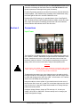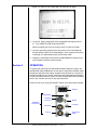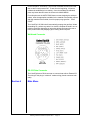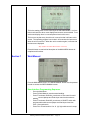
1
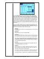
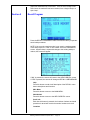
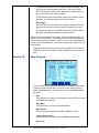
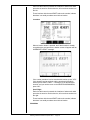
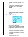
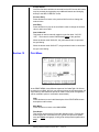
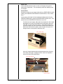
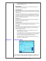
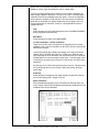
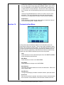
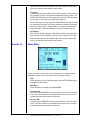
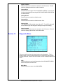
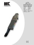
CobraTig® 150 XM
Owner’s Manual
Product:
CobraTig®
Manual:
091-0541
Serial:
03010001
Voltage Rating: 100/120/208/
240VAC
Revision:
Jan 2003
Model Number: 254-151
SAFETY CONSIDERATIONS
ELECTRIC ARC WELDING EQUIPMENT
CAUTION : READ BEFORE ATTEMPTING INSTALLATION, OPERATION
OR MAINTENANCE OF THIS EQUIPMENT
1-1 INTRODUCTION
This equipment is intended for ultimate
application by commercial/industrial users
and for operation by persons trained and
experienced in the use and maintenance
of welding equipment. Operation should
not be undertaken without adequate training in the use of such equipment. Training
is available from many public and private
schools or similar facilities.
Safe practices in the installation, operation and maintenance of this equipment
requires proper training in the art, a careful study of the information provided with
the equipment, and the use of common
sense. Rules for safe use are generally
provided by suppliers of welding power
sources, compressed gas suppliers, and
electrode suppliers. Careful compliance
with these rules will promote safe use of
this equipment.
The following Safety Rules cover some
of the more generally found situations.
READ THEM CAREFULLY. In case of
any doubt, obtain qualified help before
proceeding.
1-2 GENERAL PRECAUTIONS
A. Burn Prevention
ELECTRIC ARC WELDING PRODUCES
HIGH INTENSITY HEAT AND ULTRAVIOLET RADIANT ENERGY WHICH MAY
CAUSE SERIOUS AND PERMANENT
EYE DAMAGE AND WHICH MAY DAMAGE ANY EXPOSED SKIN AREAS.
Wear helmet with safety goggles or
glasses with side shields underneath,
appropriate filter lenses or plates (protected by clear cover glass). This is a
must for welding or cutting (and chipping)
to protect the eyes from radiant energy
and flying metal. Replace cover glass
when broken, pitted, or spattered.
Medical first aid and eye treatment.
First aid facilities and a qualified first aid
person should be available for each shift
unless medical facilities are close by for
immediate treatment of flash burns of the
eyes and skin burns.
Wear protective clothing - leather (or
asbestos) gauntlet gloves, hat, and high
safety-toe shoes. Button shirt collar and
pocket flaps, and wear cuffless trousers
to avoid entry of sparks and slag.
Avoid oily or greasy clothing. A spark
may ignite them.
Flammable hair preparations should not
be used by persons intending to weld
or cut.
Hot metal such as electrode stubs and
work pieces should never be handled
without gloves.
Ear plugs should be worn when working
on overhead or in a confined space. A
hard hat should be worn when others work
overhead.
B. Toxic Fume Prevention
WARNING: The use of this product may result in exposure to chemicals known to the
State of California to cause cancer and birth
defects or other reproductive harm.
Adequate ventilation. Severe discomfort, illness or death can result from fumes, vapors,
heat, or oxygen enrichment or depletion that
welding (or cutting) may produce. Prevent
them with adequate ventilation. NEVER
ventilate with oxygen.
Lead-, cadmium-, zinc-, mercury-, berylliumbearing and similar materials, when welded
or cut, may produce harmful concentrations
of toxic fumes. Adequate local exhaust ventilation must be used, or each person in the
area, as well as the operator, must wear an
air-supplied respirator. For beryllium, both
must be used.
Metals coated with or containing materials
that emit toxic fumes should not be heated
unless coating is removed form the work
surface, the area is well ventilated, or the
operator wears an air-supplied respirator.
Work in a confined space only while it is
being ventilated and, if necessary, while
wearing an air-supplied respirator.
Gas leaks in a confined space should be
avoided. Leaked gas in large quantities can
change oxygen concentration dangerously.
Do not bring gas cylinders into a confined
space.
Leaving confined space, shut OFF gas supply at source to prevent possible accumulation of gases in the space if downstream
valves have been accidentally opened or
left open. Check to be sure that the space
is safe before reentering it.
Vapors from chlorinated solvents can be decomposed by the heat of the arc (or flame)
to form PHOSGENE, a highly toxic gas,
and other lung and eye irritating products.
The ultraviolet (radiant) energy of the arc
can also decompose trichloroethylene and
perchloroethylene vapors to form phosgene.
DO NOT WELD or cut where solvent vapors
can be drawn into the welding or cutting
atmosphere or where the radiant energy
can penetrate to atmospheres containing
even minute amounts of trichloroethylene
or perchloroethylene.
C. Fire and Explosion Prevention
Causes of fire and explosion are: combus-
tibles reached by the arc, flame, flying
sparks, hot slag, or heated material, misuse of compressed gases and cylinders,
and short circuits.
BE AWARE THAT flying sparks or falling slag can pass through cracks, along
pipes, through windows or doors, and
through wall or floor openings, out of
sight of the goggled operator. Sparks
can fly many feet.
To prevent fires and explosion:
Keep equipment clean and operable, free
of oil, grease, and (in electrical parts) of
metallic particles that can cause short
circuits.
If combustibles are in area, do NOT weld
or cut. Move the work if practicable, to
an area free of combustibles. Avoid paint
spray rooms, dip tanks, storage areas,
ventilators. If the work cannot be moved,
move combustibles at least 35 feet away,
out of reach of sparks and heat; or protect
against ignition with suitable and snug-fitting, fire-resistant covers or shields.
Walls touching combustibles on opposite
sides should not be welded on (or cut).
Walls, ceilings, and floor near work
should be protected by heat-resistant
covers or shields.
Fire watcher must be standing by with
suitable fire extinguishing equipment
during and for some time after welding
or cutting if:
1. Appreciable combustibles (including building construction) are within
35 feet.
2. Appreciable combustibles are further than 35 feet, but can be ignited by
sparks.
3. Openings (concealed or visible) in
floors or walls within 35 feet may expose
combustibles to sparks.
4. Combustibles adjacent to walls, ceilings, roofs, or metal partitions can be
ignited by radiant or conducted heat.
Hot work permit should be obtained
before operation to ensure supervisor’s
approval that adequate precautions have
been taken.
After work is done, check that area is free
of sparks, glowing embers, and flames.
An empty container that held combustibles, or that can produce flammable or
toxic vapors when heated, must never
be welded on or cut, unless container
has first been cleaned in accordance with
industry standards.
This includes: a thorough steam or
caustic cleaning (or a solvent of water
washing, depending on the combustible’s
solubility), followed by purging and inerting with nitrogen or carbon dioxide, and
using protective equipment.
hazardous.
Water-filling just below working level may
substitute for inerting.
Prohibited use. Never use a cylinder or its
contents for other than its intended use,
NEVER as a support or roller.
A container with unknown contents
should be cleaned (see paragraph
above). Do NOT depend on sense of
smell or sight to determine if it is safe to
weld or cut.
Hollow castings or containers must be
vented before welding or cutting. They
can explode.
Explosive atmospheres. NEVER weld
or cut where the air may contain flammable dust, gas, or liquid vapors (such
as gasoline).
D. Compressed Gas Equipment
The safe handling of compressed gas
equipment is detailed in numerous
industry publications. The following
general rules cover many of the most
common situations.
1. Pressure Regulators
Regulator relief valve is designed to protect only the regulator from overpressure;
it is not intended to protect any downstream equipment. Provide such protection with one or more relief devices.
Never connect a regulator to a cylinder
containing gas other than that for which
the regulator was designed.
Remove faulty regulator from service immediately for repair (first close cylinder
valve). The following symptoms indicate
a faulty regulator:
Leaks - if gas leaks externally.
Excessive Creep - if delivery pressure
continues to rise with downstream valve
closed.
Faulty Gauge - if gauge pointer does
not move off stop pin when pressurized,
nor returns to stop pin after pressure
release.
Repair. Do NOT attempt repair. Send
faulty regulators for repair to manufacturer’s designated repair center, where
special techniques and tools are used by
trained personnel.
Empties: Keep valves closed, replace caps
securely; mark MT; keep them separate
from FULLS, and return promptly.
Locate or secure cylinders so they cannot
be knocked over.
Passageways and work areas. Keep cylinders clear of areas where they may be
stuck.
Transporting cylinders. With a crane, use
a secure support such as a platform or
cradle. Do NOT lift cylinders off the ground
by their valves or caps, or by chains, slings,
or magnets.
Do NOT expose cylinders to excessive heat,
sparks, slag, and flame, etc. that may cause
rupture. Do not allow contents to exceed 55
degrees C (130 degrees F.) Cool with water
spray where such exposure exists.
Protect cylinders, particularly valves from
bumps, falls, falling objects, and weather.
Replace caps securely when moving cylinders.
Stuck valve. Do NOT use a hammer or
wrench to open a cylinder valve that cannot
be opened by hand. Notify your supplier.
Mixing gases. NEVER try to mix any gases
in a cylinder.
NEVER refill any cylinder.
Cylinder fittings should never be modified
or exchanged.
3. Hose
Prohibited use. Never use hose other
than that designed for the specified gas. A
general hose identification rule is: red for
fuel gas, green for oxygen, and black for
inert gases.
Use ferrules or clamps designed for the
hose (not ordinary wire or other substitute)
as a binding to connect hoses to fittings.
No copper tubing splices. Use only standard brass fittings to splice hose.
Avoid long runs to prevent kinks and abuse.
Suspend hose off ground to keep it from
being run over, stepped on, or otherwise
damaged.
2. Cylinders
Cylinders must be handled carefully to
prevent leaks and damage to their walls,
valves, or safety devices:
Coil excess hose to prevent kinks and
tangles.
Avoid electrical circuit contact with cylinders including third rails, electrical wires,
or welding circuits. They can produced
short circuit arcs that may lead to a serious accident. (See 1-3C)
Examine hose regularly for leaks, wear,
and loose connections. Immerse pressured
hose in water; bubbles indicate leaks
ICC or DOT marking must be on each cylinder. It is an assurance of safety when
the cylinder is properly handled.
4. Proper Connections
Clean cylinder valve outlet of impurities that
may clog orifices and damage seats before
connecting regulator. Except for hydrogen,
crack valve momentarily, pointing outlet
away from people and sources of ignition.
Wipe with a clean, lintless cloth.
Identifying gas content. Use only cylinders with name of gas marked on them;
do not rely on color to identify gas content. Notify supplier if unmarked. NEVER
DEFACE or alter name, number, or other
markings on a cylinder. It is illegal and
Protect hose from damage by sharp edges,
and by sparks, slag, and open flame.
Repair leaky or worn hose by cutting area
out and splicing. Do NOT use tape.
Match regulator to cylinder. Before connecting, check that the regulator label and
cylinder marking agree, and that the
regulator inlet and cylinder outlet match.
NEVER Connect a regulator designed
for a particular gas or gases to a cylinder
containing any other gas.
Tighten connections. When assembling
threaded connections, clean and smooth
seats where necessary. Tighten. If connection leaks, disassemble, clean, and
retighten, using properly fitting wrench.
Adapters. Use a CGA adapter (available
from your supplier) between cylinder and
regulator, if one is required. Use two
wrenches to tighten adapter marked
RIGHT and LEFT HAND threads.
Regulator outlet (or hose) connections
may be identified by right hand threads
for oxygen and left hand threads (with
grooved hex on nut or shank) for fuel
gas.
5. Pressurizing Steps:
Drain regulator of residual gas through
suitable vent before opening cylinder
(or manifold valve) by turning adjusting
screw in (clockwise). Draining prevents excessive compression heat at
high pressure seat by allowing seat to
open on pressurization. Leave adjusting
screw engaged slightly on single-stage
regulators.
Stand to side of regulator while opening
cylinder valve.
Open cylinder valve slowly so that regulator pressure increases slowly. When
gauge is pressurized (gauge reaches
regulator maximum) leave cylinder
valve in following position: for oxygen
and inert gases, open fully to seal stem
against possible leak; for fuel gas, open
to less than one turn to permit quick
emergency shut-off.
Use pressure charts (available from
your supplier) for safe and efficient
recommended pressure settings on
regulators.
Check for leaks on first pressurization
and regularly thereafter. Brush with soap
solution. Bubbles indicate leaks. Clean
off soapy water after test; dried soap is
combustible.
E. User Responsibilities
Follow all Safety Rules.
Remove leaky or defective equipment
from service immediately for repair.
Read and follow user manual instructions.
F. Leaving Equipment Unattended
Close gas supply at source and drain
gas.
G. Rope Staging-Support
Rope staging-support should not be
used for welding or cutting operation;
rope may burn.
1-3 ARC WELDING
Comply with precautions in 1-1, 1-2,
and this section. Arc Welding, properly
done, is a safe process, but a careless
operator invites trouble. The equipment
carries high currents at significant voltages. The arc is very bright and hot.
Sparks fly, fumes rise, ultraviolet and
infrared energy radiates, weldments are
hot, and compressed gases may be used.
The wise operator avoids unnecessary
risks and protects himself and others
from accidents.
A. Burn Protection
Comply with precautions in 1-2.
The welding arc is intense and visibly
bright. Its radiation can damage eyes,
penetrate lightweight clothing, reflect
from light-colored surfaces, and burn
the skin and eyes. Skin burns resemble
acute sunburn; those from gas-shielded
arcs are more severe and painful.
DON’T GET BURNED; COMPLY WITH
PRECAUTIONS.
1. Protective Clothing
Wear long-sleeve clothing in addition to
gloves, hat, and shoes. As necessary,
use additional protective clothing such
as leather jacket or sleeves, flameproof
apron, and fire-resistant leggings. Avoid
outer garments of untreated cotton.
Bare skin protection. Wear dark, substantial clothing. Button collar to protect
chest and neck, and button pockets to
prevent entry of sparks.
2. Eye and Head Protection
Protect eyes from exposure to arc. Eyes
may be damaged by radiant energy when
exposed to the electric arc, even when
not looking in the direction of the arc.
Never look at an electric arc without
protection.
Welding helmet or shield containing a
filter plate shade no. 12 or denser must
be used when welding. Place over face
before striking arc.
Protect filter plate with a clear cover
plate.
Cracked or broken helmet or shield
should NOT be worn; radiation can be
passed through to cause burns.
Cracked, broken, or loose filter plates
must be replaced IMMEDIATELY. Replace clear cover plate when broken,
pitted, or spattered.
Flash goggles with side shields MUST be
worn under the helmet to give some protection to the eyes should the helmet not
be lowered over the face before an arc
is struck. Looking at an arc momentarily
with unprotected eyes (particularly a high
intensity gas-shielded arc) can cause a
retinal burn that may leave a permanent
dark area in the field of vision.
3. Protection of Nearby Personnel
Enclose the welding area. For production
welding, a separate room or enclosed bay
is best. In open areas, surround the operation with low-reflective, noncombustible screens or panels. Allow for free air
circulation, particularly at floor level.
Viewing the weld. Provide face shields
for all persons who will be looking directly
at the weld.
Others working in area. See that all persons
are wearing flash goggles.
Before starting to weld, make sure that
screen flaps or bay doors are closed.
B. Toxic Fume Prevention
Comply with precautions in 1-2B.
Generator engine exhaust must be vented
to the outside air. Carbon monoxide can
kill.
C. Fire and Explosion Prevention
Comply with precautions in 1-2C.
Equipment’s rated capacity. Do not overload arc welding equipment. It may overheat cables and cause a fire.
Loose cable connections may overheat or
flash and cause afire.
Never strike an arc on a cylinder or other
pressure vessel. It creates a brittle area that
can cause a violent rupture or lead to such a
rupture later under rough handling.
D. Compressed Gas Equipment
Comply with precautions in 1-2D.
E. Shock Prevention
Exposed electrically hot conductors or
other bare metal in the welding circuit, or
in ungrounded, electrically-HOT
equipment can fatally shock a person whose
body becomes a conductor. DO NOT
STAND, SIT, LIE, LEAN ON, OR TOUCH a
wet surface when welding without suitable
protection.
To protect against shock:
Keep body and clothing dry. Never work
in damp area without adequate insulation
against electrical shock. Stay on a dry
duckboard, or rubber mat when dampness
or sweat cannot be avoided. Sweat, sea
water, or moisture between body and an
electrically HOT part - or grounded metal
- reduces the body surface electrical resistance, enabling dangerous and possibly
lethal currents to flow through the body.
1. Grounding the Equipment
When installing, connect the frames of
each unit such as welding power source,
control, work table, and water circulator to
the building ground. Conductors must be
adequate to carry ground currents safely.
Equipment made electrically HOT by stray
currents may shock, possibly fatally. Do
NOT GROUND to electrical conduit, or to a
pipe carrying ANY gas or a flammable liquid
such as oil or fuel.
Three-phase connection. Check phase
requirement of equipment before installing. If only three-phase power is available,
connect single-phase equipment to only two
wires of the three-phase line. Do NOT connect the equipment ground lead to the third
(live) wire, or the equipment will become
electrically HOT - a dangerous condition
that can shock, possibly fatally.
Before welding, check ground for continuity.
Be sure conductors are touching bare metal
of equipment frames at connections.
If a line cord with a ground lead is provided
with the equipment for connection to a
switch box, connect the ground lead to the
grounded switch box. If a three-prong plug
is added for connection to a grounded
mating receptacle, the ground lead must
be connected to the ground prong only.
If the line cord comes with a three-prong
plug, connect to a grounded mating receptacle. Never remove the ground
prong from a plug, or use a plug with a
broken ground prong.
2. Connectors
Fully insulated lock-type connectors
should be used to join welding cable
lengths.
3. Cables
Frequently inspect cables for wear,
cracks, and damage. IMMEDIATELY
REPLACE those with excessively worn
or damaged insulation to avoid possibly
lethal shock from bared cable. Cables
with damaged areas may be taped to
give resistance equivalent to original
cable.
Keep cable dry, free of oil and grease,
and protected from hot metal and
sparks.
4. Terminals and Other Exposed
Parts
Terminals and other exposed parts of
electrical units should have insulating
covers secured before operation.
5. Electrode Wire
Electrode wire becomes electrically
HOT when the power switch of gas
metal-arc welding equipment is ON and
welding gun trigger is pressed. Keep
hands and body clear of wire and other
HOT parts.
6. Safety Devices
Safety devices such as interlocks and
circuit breakers should not be disconnected or shunted out.
Before installation, inspection, or service
of equipment, shut OFF all power, and
remove line fuses (or lock or red-tag
switches) to prevent accidental turning
ON of power. Disconnect all cables from
welding power source, and pull all 115
volts line-cord plugs.
Do not open power circuit or change
polarity while welding. If, in an emergency, it must be disconnected, guard
against shock burns or flash from switch
arcing.
Leaving equipment unattended. Always
shut OFF, and disconnect all power to
equipment.
Power disconnect switch must be available near the welding power source.
THIS PAGE INTENTIONALLY BLANK
CobraTig 150 Owner's Manual P/N 091-0541
Table of Contents
INTRODUCTION........................................................................8
Section 1
Technical Information............................................9
Section 2
Mechanical Information.........................................9
Section 3
Weldhead and Torches..........................................9
Section 4
Connections.......................................................10
Section 5
Operation...........................................................12
Section 6
Main Menu ........................................................14
Section 7
Weld Manual .....................................................14
Section 8
Weld Orbital.......................................................16
Section 9
Recall Program...................................................17
Section 10
Save Program.....................................................18
Section 11
Auto Program Generator......................................20
Section 12
Print Menu ........................................................21
Section 13
Calibration Menu.................................................23
Section 14
Communication Menu..........................................26
Section 15
Setup Menu........................................................27
Section 16
Diagnostic Menu ................................................28
CobraTig 150 Owner's Manual P/N 091-0541
THIS PAGE INTENTIONALLY BLANK
CobraTig 150 Owner's Manual P/N 091-0541
INTRODUCTION
The portable, lightweight CobraTig® 150 XM with SmartArc®
provides the automatic control you need to deliver repeatability,
verification and traceability in high-integrity orbital and manual
welding.
SmartArc® software develops a near ideal weld procedure
through the use of our Automatic Procedure Generator. Just
enter the tube outside diameter and wall thickness... The rest is
automatic.
This version of CobraTig®Software and Hardware has the latest
in Micro-Tig Technology. The system is now capable of going
down to 0.1 amps. High Voltage Pulse automatic arc starting
from 0.5 to 25 amps.
Make the most of your offsite and onsite welding operations.
With the CobraTig® 150 XM, you’ll weld circles around the competition.
CobraTig 150 Owner's Manual P/N 091-0541 - Page Section 1
Technical Information
Line Power:
(+/- 10%)
Output Current:
Minimum Arc Starting:
Pulse Rate:
Arc Voltage:
Loop Response:
Current Regulator Freq:
Motor Control:
Memory Storage:
Section 2
Mechanical Information
Section 3
100VAC 50/60 Hz Single Phase, 15A
120VAC 50/60 Hz Single Phase, 15A
208VAC 50/60 Hz Single or Three Phase, 30A
230VAC 50/60 Hz Single or Three Phase, 30A
0.1~150A (+/- 1%), Constant or Pulsed
0.5 to 25 Amps
0.01 to 2.25 Seconds Per Pulse
65VDC Open Circuit, up to 26 welding VDC
1.5 KHz
30 KHz
24VDC, 2A min., DC Tachometer Feedback.
25 Weld Procedures
Weight:
Height:
Width:
Length:
42 lbs / 19.1 Kg
14 in. / 35.6 cm
8.5 in. / 21.6 cm
19 in. / 48.3 cm
Weldhead and Torches
For robust solutions for orbital weld applications, the CopperHeads are ideal
cost savers for sanitary and high-pressure tube systems.
The CopperHead series are our most cost effective and rugged in-place orbital weldheads offered in three models. The CopperHead models 5001 (1/8
- 1 inch OD), 5002 (1/4 - 2 inche OD) and 5003 (1/2 - 3 inch OD) each offer
versatility and high-output production rates.
The water-cooled, narrow profile CopperHeads are lightweight and easy to
handle for those awkward welds with limited access.
The high-output model 5000 (1/16 - 3/4 inch OD) is a robust heavy-duty
water-cooled tube and minature weld fitting in-place orbital weldhead for high
purity tube systems.
All MK weldheads can be utilized as bench mounted or remotely controlled
untis.
The models and the capacities are as follows:
MODEL
4000
5000
5001
5002
5003
5006
CAPACITY (Max. OD)
1/16” - 1/8”
1/16” - 3/4”
1/8” - 1”
1/4” - 2”
1/2” - 3”
2" OD - 6" NPS
With a simple power connector pigtail (P/N 005-0619), all previously sold MK
Orbital weldheads will adapt to the CobraTig® 150 XM. You must change
the previous electrode and ground cable connectors from the push-in type to
a twist-lock type.
CobraTig 150 Owner's Manual P/N 091-0417 - Page 10
The order numbers for the twist-lock type are: P/N 153-0755 Electrode (male
connector to exchange for the black connector) and P/N 153-0813 Ground
(female connector to exchange for the green connector).
For MicroTig welding operations, the MicroTig Accessory Kit (P/N 005-0670)
is also available. This contains all the necessary items needed when using
the CobraTig®150 XM unit in the WELD MANUAL mode.
Precision MicroTig Technology is a standard feature of the CobraTig®150
XM. The ideal precision manual welder produces reliable, smooth arc starts
at 0.5 amps and is perfect for welding precision thin wall exotic materials
such as titanium and stainless steel or fine wire sizes.
Section 4
Connections
Input Power
The CobraTig® 150 XM can operate on any of four different input power values: 100VAC, 120VAC, 208/230VAC Single Phase and, 208/230VAC Three
Phase. Attached to the unit is a 12ft power cable that comes wired from
the factory ready for 120VAC. Even though the installed plug is only three
prongs, there are four wires in the cable, ready for three phase power.
DANGER
DISCONNECT ALL POWER TO THE UNIT PRIOR TO CHANGING THE POWER
TAPS. FAILURE TO DO THIS WILL RESULT IN SERIOUS BODILY HARM AND
EXTENSIVE EQUIPMENT DAMAGE.
To change the input power type, three changes have to be made to the CobraTig® 150 XM unit: first change the voltage jumper, then the voltage selector cable and the plug on the end of the cable. You will need a 1/4” nutdriver
wrench and a #2 Phillips head screwdriver.
Using the nutdriver, remove all the 1/4” hex head screws from the cover of
the unit, then lift the cover off. Locate TB1 on the lower-right-rear side of the
unit, from the front. Using the Phillips head screwdriver to change the taps,
follow the directions below:
Configure Voltage Selector Jumper at TB1 terminals 1-3, for the input
voltage, 100V/120V or 208V/230V. Remove and flip over to change (see
Jumper Configuration image).
CobraTig 150 Owner's Manual P/N 091-0541 - Page 11
208/230V
100/120V
100V 120V 208V 230V
100V 120V 208V 230V
1 2 3 4 5 6 7 8
1 2 3 4 5 6 7 8
TB1 Configured
for 100/120VAC
TB1 Configured
for 208/230VAC
Jumper Configuration
Move “Voltage Selector Cable” to the corresponding input voltage terminal of
TB1 for 100V, 120V, 208V, or 230V.
After the input voltage taps have been configured, then change the plug on
the end of the power cable to match.
SmartArc® Software Update
When viewing the MAIN MENU of the CobraTig® 150 XM, the currently
loaded software version will appear across the middle of the screen. Once
the software update is properly performed, this version number will show the
newly loaded version number.
In order to update the SmartArc® software in the CobraTig® 150 XM, the following items are needed:
• CobraTig® 150 XM
• PC running DOS
• RS-232 serial cable/null modem wiring (female connector both ends)
• Diskette with UPDAT150.exe and UPGRADE.150 files
The SmartArc® software updating procedure is as follows:
1. Connect the RS-232 serial cable between the PC (9 or 25 pin - where
mouse usually connects) and the rear panel of the CobraTig® 150 XM (9
pin).
2. Simultaneously while pressing the F10 button (lower-right hand button)
on the CobraTig® 150 XM front panel, turn on the CobraTig® 150 XM.
The screen should display a “READY TO RECEIVE…” prompt, as shown
CobraTig 150 Owner's Manual P/N 091-0417 - Page 12
below. If it does not, turn CobraTig® 150 XM off and try again.
3. On the PC, while running DOS insert the diskette and change to drive
A:\. Type UPDAT150.EXE and press ENTER.
When prompted, type in the port number (see PC owner’s manual).
4. Once the upgrading program starts, the screen on the CobraTig® 150
XM will show the status of the downloading. Once complete, turn off the
CobraTig® 150 XM and disconnect RS-232 serial cable.
5. Restart the CobraTig® 150 and view the MAIN MENU to inspect for the
new SmartArc® software version number.
Section 5
OPERATION
To operate the CobraTig® 150 XM portable orbital welding unit, plug in any
standard MK Orbital weldhead to the rear panel, and perform the basic setup
procedures associated with collets, tungsten, and concentricity. Plug the CobraTig® 150 XM into any 120VAC electrical outlet (independent and isolated
circuits will produce the best results), connect the quick disconnect gas fitting
into the unit, and the other end to any argon flowmeter.
Power the unit on by rocking the ON/OFF switch to the ON position (located
ON/OFF
Weldhead Gas
Amphenol
Connector
Weldhead
Connections
Electrode
Ground
CobraTig 150 Owner's Manual P/N 091-0541 - Page 13
RS232
Input Gas
Input Power
Cable
on the rear panel - see below). The unit will remember the last screen that
was on when it was powered off. To start from the beginning, it is best to
calibrate the weldhead prior to starting. Once the weldhead is calibrated,
press any button that will return the screen to the MAIN MENU.
From this point use the AUTO PROG button to start designing the weld procedure, enter the appropriate variables for the material to be welded, prepare
and align material to be welded, check for proper purge gas flow... Press
START.
The CobraTig® 150 XM unit will automatically prepurge the gas flow, initiate
the welding arc, perform any tacks if so desired, complete the weld in one or
multiple revolutions depending on procedure design and return the rotor to
home position while the postpurge gas is flowing. Weld complete.
Weldhead Connector
RS-232 Data Connector
The CobraTig®uses a DB-9 connector to communicate with an External PC.
The wiring for this plug is “cable/null” modem wiring (female connector both
ends).
Section 6
Main Menu
CobraTig 150 Owner's Manual P/N 091-0417 - Page 14
This is the starting menu for the CobraTig® 150 XM orbital welder. It is from
this menu that all the other menu displays and screens are accessible. From
each menu display, there is a one-step button back to this menu.
This is not to say that every time this unit is turned on that it will start at this
screen. The operating program is such that it will remember the last screen
when the unit is turned off. When the unit is turned on again, it will start with
the last screen displayed.
Help (Defines the Main Menu button selections)
Press this button to read a brief description of the MAIN MENU button descriptions and functions.
Section 7
Weld Manual
From the MAIN MENU screen, the WELD MANUAL button must be pressed
in order to access the WELD MANUAL screen.
User Interface Programming Sequence
·
·
·
·
·
From the Main Menu.
Press F2 Weld Manual, permits manual welding.
Press F7 and enter Pedal On, permits use of foot control for weld current Upslope and Final slope control and continuous
welding.
Press F7 and enter Pedal Off, permits use of ON/OFF switch with
programmable weld current upslope and final slope times from
0.00~1.0 seconds each.
Press F4 or F9 and scroll to Curr. H. (A), high weld current in amps.
CobraTig 150 Owner's Manual P/N 091-0541 - Page 15
Note: The Current High Amps establishes the maximum output in
amps that may be obtained.
· Press F5 or F10 and enter High current value from 0.2~150 amps.
· Press F4 or F9 and scroll to Curr. L. (A), low weld current in amps.
· Press F5 or F10 and enter Low current value from 0.2~150 amps.
· Press F4 or F9 and scroll to Pulse H. (S), high weld current pulse time.
· Press F5 or F10 and enter High weld current pulse time from 0.00~0.99 seconds.
· Press F4 or F9 and scroll to Pulse L. (S), low weld current pulse
time.
· Press F5 or F10 and enter Low weld current pulse time from
0.00~0.99 seconds.
· Press F4 or F9 and scroll to Pre-Gas (S), pre-purge gas time.
· Press F5 or F10 and enter pre-purge gas time from 0.0~9.9 seconds.
· Press F4 or F9 and scroll to Post-Gas (S), post-purge gas time.
· Press F5 or F10 and enter post-purge gas time from 0.0~9.9
seconds.
· Press F4 or F9 and scroll to Strike (A), arc strike weld current.
· Press F5 or F10 and enter arc strike weld current from 0.1~25.0
amps.
· Press Foot Control to maximum and hold for duration of weld
· Press F6 Print Weld wave form graphics from integral printer
WELD MANUAL SCREEN DISPLAY
·
·
·
·
·
·
·
·
·
·
·
Section 8
F1, Start/Stop, used for manual Start/Stop operations without a foot control.
F2, Main Menu, returns to the Main Menu display.
F3, Weld Orbital, returns to the Weld Orbital display.
F4, Scroll UP, scrolls the highlighted field from one demand
parameter to the next demand parameter.
F5, Adjust Up, increases the numerical value of the demand
parameter selected. As this button is pressed for each parameter a
vertical bar graph displays the increasing value, both numerically and
graphically from the bar graph. For most parameters, a maximum
value is obtained once the vertical bar graph has reached the top of
the scale. Also, there is a change in the sound once the top of the
scale has been reached. The sound changes from a single beep to a
triple beep.
F6, Print Weld, Data-Monitoring of manual weld produces a graphical
real time wave form of welding amps and arc volts.
F7, Pedal On, selects the variable remote foot control for operation.
F7, Pedal Off, selects the On/Off switch control and permits
additional programming of weld current Upslope time in seconds and
Final Slope weld current time in seconds.
F8, Blank, no function control.
F9, Scroll Down, scrolls the highlighted field from one demand
parameter to the next demand parameter.
F10, Adjust Down, decreases the numerical value of the demand
parameter selected. As this button is pressed for each parameter a
vertical bar graph displays the decreasing value, both numerically
and graphically from the bar graph. For most parameters, a minimum
value is obtained once the vertical bar graph has reached the bottom
of the scale. Also, there is a change in the sound once the bottom of
the scale has been reached. The sound changes from a single beep
to a triple beep.
Weld Orbital
CobraTig 150 Owner's Manual P/N 091-0417 - Page 16
From the MAIN MENU screen press this button to select orbital welding.
Once at the WELD ORBITAL screen, use the RECALL PROGRAM button
at the bottom of the screen to select from the library of customer designed
and saved procedures, or return to the MAIN MENU and use the APG (Auto
Procedure Generation) function in order to design a new weld procedure.
Use the SCROLL UP, SCROLL DOWN, ADJUST UP, and ADJUST DOWN
buttons to select and modify specific weld procedure parameters. Then
when all variables are set, press the START/STOP button to initiate the welding process.
Once at the WELD ORBITAL screen, the last orbital weld procedure is displayed from memory. This is the default procedure and ready to weld. If a
different weld procedure is desired, it can either be recalled from memory or,
developed using the Auto Program Generator (APG).
Start/Stop
Pressing this button will start the prepurge gas flowing and start the welding procedure.
Main Menu
Press this button to return to the MAIN MENU.
Print Weld
Press the PRINT WELD button to obtain a printout of the last weld procedure parameters and the wave form strip chart of the completed weld.
This will give a weld procedure printout, first showing the description of
the procedure, followed by the all the welding parameters, then by Limit
and Deviation parameters, then by the actual strip chart of the weld current, arc voltage and motor speed.
Scroll Up
Press this button in order to scroll and select the highlighted field from
one DEMAND parameter up to the next.
Adjust Up
After the SCROLL UP or SCROLL DOWN buttons have been used to
select a parameter to be modified, press the ADJUST UP button to increase the numerical value of that parameter.
As this button is pressed for each parameter a vertical bar graph shows
the increasing value, both numerically and in height of the bar graph.
For most parameters, a maximum value is obtained once the vertical bar
CobraTig 150 Owner's Manual P/N 091-0541 - Page 17
graph has reached the top of the scale. There is also a change in the
sound once the maximum has been reached, from a single ‘beep’ to a
triple ‘beep’.
Section 9
Recall Program
Press the RECALL PROGRAM in order to access the library of operator
saved weld procedures.
NOTE: If the currently used procedure is not saved, a warning screen
of text will prompt for a ‘YES’ or ‘NO’ answer: this is the OVERWRITE
screen. Anytime there is a potential change to the existing weld procedure, this screen will appear.
If ‘NO’ is pressed, the screen will return to the WELD ORBITAL screen.
If ‘YES’ is pressed, the screen will change to RECALL USER MEMORY.
Help
Press this button to read a brief description of the RECALL menu
button descriptions and functions.
Main Menu
Press this button to return to the MAIN MENU.
Weld Orbital
Press this button to return to the WELD ORBITAL screen.
Scroll Left
Each time this button is pressed, the locations of where each weld
procedure is saved will move three number locations to the left.
Locations
CobraTig 150 Owner's Manual P/N 091-0417 - Page 18
The bottom three buttons on this screen indicate the number of the
location where weld procedures are saved. Using the SCROLL
LEFT and SCROLL RIGHT button, will move the locations accordingly to show the status of each location.
Those locations with the word EMPTY above the number, indicate
that there is no weld procedure saved in that location.
Scroll Right
Each time this button is pressed, the locations of where each weld
procedure is saved will move three number locations to the right.
Those locations with the word EMPTY above the number, indicate
that there is no weld procedure saved in that location.
If the current weld program is a temporary, unsaved/modified program, the
RECALL screen will be blank. This indicates that the current weld program
has not been saved to any location. However, if the current weld program is
from one of the saved locations, this screen will display the location it is presently saved at.
Press any button that does not contain the word EMPTY. Press WELD
ORBITAL to return to that screen to begin welding with the saved procedure.
Section 10
Save Program
Once a weld procedure has been developed, it is generally a good idea
to save it for use at a later date. In order to do this, simply press the
SAVE PROGRAM button. This will change to the SAVE USER MEMORY screen.
Help
Press this button to read a brief description of the SAVE menu button
descriptions and functions.
Main Menu
Press this button to change to the MAIN MENU.
Weld Orbital
Press this button to change to the WELD ORBITAL screen.
Communication Menu
Press this button to change to the COMMUNICATION MENU.
Scroll Left
CobraTig 150 Owner's Manual P/N 091-0541 - Page 19
Each time this button is pressed, the locations of where each weld
procedure is saved or can be saved to, will move three numbers to
the left.
Those locations with the word EMPTY above the number, indicate
that there is no weld procedure saved in that location.
Locations
When a location button is pressed, and if that location is already
occupied with a weld procedure, another screen will appear with an
OVERWRITE VERIFY message.
If the current procedure is to be saved at this location, press “YES”.
If this location is to be emptied, and the saved weld procedure
erased, press “EMPTY ONLY”. If nothing is to be done with this
location, and you need to return to the SAVE PROGRAM MENU,
press “NO”.
Scroll Right
Each time this button is pressed, the locations of where each weld
procedure is saved or can be saved to, will move three numbers to
the right.
Those locations with the word EMPTY above the number, indicate
that there is no weld procedure saved in that location.
Weld Mode
CobraTig 150 Owner's Manual P/N 091-0417 - Page 20
Pressing this button will toggle the high voltage arc starter from the
prompt READY TO WELD (high voltage enabled) to READY TO TEST
(high voltage disabled). This toggle is visible at the bottom of the WELD
ORBITAL screen.
Scroll Down
Press this button in order to scroll the highlighted field from one DEMAND parameter down to the next. Adjustment of each parameter is
performed using the ADJUST UP or ADJUST DOWN buttons.
Adjust Down
After the SCROLL UP or SCROLL DOWN buttons have been used to
select a parameter to be modified, press the ADJUST DOWN button to
decrease the numerical value of that parameter.
As this button is pressed for each parameter a vertical bar graph shows
the decreasing value, both numerically and in height of the bar graph.
For most parameters, a minimum value is obtained once the vertical bar
graph has reached the bottom of the scale. There is also a change in
the sound once the minimum has been reached, from a single ‘beep’ to a
triple ‘beep’.
Section 11
Auto Program Generator
From the main menu screen press Auto Prog. The ease of using the CobraTig® 150 XM comes primarily from this feature. By simply inputting some
basic tube or pipe variables, the CobraTig® 150 XM digital controller can
generate and produce a near ideal weld procedure.
The following menu will guide the operator through basic fields of information
entry. Beginning with selections for tube or pipe and diameter and wall thickness. Additional information can be designed into the procedure that include
different pulse types, up to 5.0 seconds motor delay time, multiple revolutions, and programming of up to 7 opposing tacks.
Help
Press this button to read a brief description of the APG button descriptions and functions.
Ignore Entries
Pressing this button at any time during the design of a weld procedure,
will automatically return the program to the MAIN MENU and lose all
entered information.
CobraTig 150 Owner's Manual P/N 091-0541 - Page 21
Accept Entries
Once the first three variables are entered into the APG screen this button
may be pressed, thus bypassing any additional features and changing
directly to the WELD ORBITAL screen.
Previous Entry
Press this button to return to the previous field in order to change the
entered value.
Next Entry
Press this button to jump to the next field in order to change the entered
value or add a new value.
Gas On/Gas Off
This button is used to manually toggle the gas flow either “ON” OR
“OFF”. This button is used to indicated the status of the gas flow.
When the button reads “GAS ON”, the gas solenoid valve is open and
the gas flowing.
When the button reads “GAS OFF”, the gas solenoid valve is closed and
the gas is not flowing.
Section 12
Print Menu
At the PRINT MENU, many different aspects of the CobraTig® 150 XM can
be printed or modified. Not only can various printouts of weld procedures, list
of procedures, and calibration reports be made but the printer configuration
can be modified to print on command or automatically.
Help
Press this button to read a brief description of the PRINT MENU button
descriptions and functions.
Main Menu
Press this button to return to the MAIN MENU.
Print Graph
This function works with the Printer After Welds function. Pressing this
button toggles the command from YES (prints weld procedure parameters plus entire weld graph), to NO (prints weld procedure parameters
only).
CobraTig 150 Owner's Manual P/N 091-0417 - Page 22
Paper Feed
Press and hold this button down in order to feed paper through the
printer driver mechanism. This is especially useful after loading a new
roll of paper.
Printer Reset
Should the printer run out of paper either during a PRINT WELD or while
feeding, the PRINTER STATUS field will read as follows, “Error, Printer
Error.”.
Once a new roll of paper has been loaded and fed through using the
PRINTER FEED button, press the PRINTER RESET button once. This
should return the PRINTER STATUS field to read, “OK”.
To load a new roll of paper, slide printer tray straight out until it stops.
Disengage the Printer Drive Mechanism by pulling down the Drive
Latch Arm on the left side of the printer. Unroll approximately 4 to
6 inches of paper from the roll and insert between the Printer Drive
Mechanism and the bottom platen, push the paper through until it
emerges from the front panel of the printer tray. Drive Latch Arm
Insert roll of paper between pins and spin backward to pull up any
extra slack in the paper. Engage the Drive Latch Arm upward to
secure the Printer Drive Mechanism.
Driver Mechanism
Bottom Platen
CobraTig 150 Owner's Manual P/N 091-0541 - Page 23
Press the PRINTER FEED button to align paper in Drive, then press
the PRINTER RESET button.
Active Program
Press this button in order to print the current weld procedure that is
loaded on the memory of the unit.
Last Orbital Weld
Press this button to obtain a printout of the last completed orbital weld.
This will give the same results as the PRINT WELD button on the WELD
ORBITAL screen.
This will give a weld procedure printout, first showing the description of
the procedure, followed by the all the welding parameters, then by Limit
and Deviation parameters, then by the actual strip chart of the weld amperage, arc voltage and motor speed.
Program List
Press this button to printout the complete listing of all the weld procedures saved in the memory of the unit.
Calibration Report
To obtain a printout of the calibration values for the motor, motor-tachometer feedback, current and voltage scales, press this button.
Print Option
This button controls the Deviation Report printout after each weld. There
are only three options available for this printout, they are as follows:
NEVER, ALWAYS & FAULTS.
In the NEVER mode, a printout of the weld will only occur if the
PRINT WELD button is pressed.
In the ALWAYS mode, at the end of every weld once the rotor returns
to the home position, it will automatically printout the resultant Strip
Chart as if the PRINT WELD button had been pressed.
In the FAULTS mode, a Strip Chart will only printout if there were
deviations in the weld sequence.
Section 13
Calibration Menu
Prior to using the CobraTig® 150 XM unit for welding, it is generally a good
idea to calibrate the output and feedback readings prior to striking an arc.
CobraTig 150 Owner's Manual P/N 091-0417 - Page 24
Options from the CALIBRATION MENU include motor output and tachometer
feedback, current output and feedback, and arc voltage input.
In order to properly calibrate this machine, you will need the following: DC
power supply capable of producing 1.0 VDC to 20.0 VDC, a certified digital
multimeter, and various standard connection leads. To aid in the calibration
of this machine, purchase kit P/N 005-0251 (The instructions included with
the kit are for the model ACL Orbital Welder, they do not apply to this unit).
Use the instructions on the HELP screen for a full explanation on how to
calibrate this unit.
Help
Press this button to read a brief description of the CALIBRATION MENU
button descriptions and functions.
Main Menu
Press this button to return to the MAIN MENU.
1.8 VDC Calibration / 18 VDC Calibration
These two keys are used in conjunction for calibrating the arc voltage
feedback circuit. Use the information on the HELP screen to perform this
calibration procedure.
Connect an external DC voltage power supply to the shunt connectors
labeled ‘ARC VOLTAGE’ and adjust to 1.8 VDC input. Reference the
VDC bar graph on the LCD screen, and use the ADJUST UP or ADJUST
DOWN buttons to match bar graph to input value. Once bar graph value
is matched to the input value, press the 1.8 VDC button, this will set the
calibration.
Set the input to 18.0 VDC and repeat the above process. The procedure
will cycle through twice for an average reading and setting, then quit
when ready.
Adjust Up
Press this button to adjust the bar graph setting to match that of the reference value being read - voltage or current.
Motor Calibration
With the weldhead plugged into the CobraTig® 150 XM rear panel, the
motor voltage output to the weldhead, and tachometer feedback from the
weldhead rotor can be calibrated.
CobraTig 150 Owner's Manual P/N 091-0541 - Page 25
This screen will allow the operator to calibrate any orbital weldhead,
at any speed value, between 1.0 and 10.0 rpm. Using the HIGH/LOW
button, select the respective speed value and use the ADJUST UP and
ADJUST DOWN buttons to select the rpm value required.
The HIGH and LOW values can never be equal. A minimum of 1.0 rpm
will separate the two values. If the LOW value is increased, the HIGH
will increase, with the 1.0 rpm difference between them. Similarly, if the
HIGH is decreased, the LOW will decrease with the 1.0 rpm difference.
Feedback of the weldhead during calibration is seen in the bar graph on
the left side of this screen.
High/Low
Toggles between the HIGH and LOW rpm speed values.
Print Report
Press this button, once calibration is complete, to view a printed report of
the calibration values.
The calibration values shown are an indication of the MOTOR/TACH
status of the weldhead. A typical printout is shown below:
MOTOR Calibration report
MOTOR gain: -4.6% Zero offset:
TACH gain:
1.9% Zero offset:
0.30 RPM
0.02 RPM
Should these MOTOR & TACH values return with number of 0.00% and
0.00 RPM, the calibration was invalid and should be re-run. Continuous results of all zeros, is an indication that the weldhead is in need of
service.
Consult the weldhead owner’s manual for proper maintenance and calibration service.
MOTOR Calibration report
MOTOR gain: 0.0%
TACH gain:
0.0%
Zero offset:
Zero offset:
0.00 RPM
0.00 RPM
NOTE: If all values for MOTOR or WELDER calibration are zeros, it
means that he calibration did not complete successfully and is not valid.
Start Calibration
Press this button to start the weldhead calibration procedure. The calibration start at the values selected using the “ADJUST UP” and “ADJUST DOWN” buttons.
Current Start
Using the calibration kit and the multimeter, calibration of the output current can be achieved in relatively short time. Using the 10 A CALIBRATION and 80 A CALIBRATION buttons, output values at these points will
properly calibrate the current for almost all applications.
10A Calibration / 80A Calibration
These two keys are used in conjunction for calibrating the output current. Use the information on the HELP screen to perform this calibration
procedure.
CobraTig 150 Owner's Manual P/N 091-0417 - Page 26
Connect the multimeter to the shunt labelled CURRENT, set the tungsten
arc gap and the gas setting and press CURRENT START. Once the 10
A arc is established, use the ADJUST UP and ADJUST DOWN buttons
to reach 2.50 mV on the multimeter. Once this mV value is read, press
the 10 A button, this will automatically jump the current to the 80 A output
value.
Use the UP and DOWN buttons to set the mV value to 20.0 mV, then
press 80 A. This cycle will repeat once more then quit when ready.
Once the arc is extinguished, the output current has been calibrated.
Adjust Down
Press this button to adjust the bar graph setting to match that of the reference value being read - voltage or current.
Section 14
Communication Menu
It is from this screen that weld procedures can be transferred from one
CobraTig® 150 XM unit to another. There are two paths available for transmission: IR (Infra Red) and Wired Cable. The IR method works much like a
TV remote, just have the two units facing each other at a distance up to 10
feet and commence transmitting. While the Wired Cable is a cable hookup
between the units’ RS232 transmission ports on the rear panels.
Help
Press this button to read a brief description of the CALIBRATION MENU
button descriptions and functions.
Main Menu
Press this button to return to the MAIN MENU.
Save Menu
Press this button to change to the SAVE MENU.
Xmit Channel
This button will toggle between two choices of transmission. Either Infra
Red or Wired Cable.
Start Receive
To begin transmitting a procedure to another machine, press this button.
Scroll Left
Each time this button is pressed, the locations of where each weld procedure is saved or can be saved to, will move three numbers to the left.
CobraTig 150 Owner's Manual P/N 091-0541 - Page 27
Those locations with the word EMPTY above the number, indicate that
there is no weld procedure saved in that location.
Locations
In order to transmit a procedure, first locate the location number of where
the procedure is saved. Then press the applicable button to send. The
START RECEIVE button will then toggle to show STOP XMIT, prompting
the operator to cancel the transmission when pressed.
On the receiving unit, simply press the START RECEIVE button to saved
the transmitting procedure, then press the location number of where the
procedure is to be saved. If the procedure is saved to a location that is
empty, the EMPTY label will disappear once the procedure is saved.
Scroll Right
Each time this button is pressed, the locations of where each weld procedure is saved or can be saved to, will move three numbers to the right.
Those locations with the word EMPTY above the number, indicate that
there is no weld procedure saved in that location.
Section 15
Setup Menu
This menu is used to set up the user’s preferences of the weld procedure
serialization, button clicks and sounds, and LCD display contrast.
Help
Press this button to read a brief description of the SETUP MENU button
descriptions and functions.
Main Menu
Press this button to change to the MAIN MENU.
Decrease S/N
This button will DECREASE the starting serial number of the next orbital
weld. The serial number is incremented before every weld, so use one
number less than actual number of next weld.
Increase S/N
This button will INCREASE the starting serial number of the next orbital
weld. The serial number is incremented before every weld, so use one
number less than actual number of next weld.
CobraTig 150 Owner's Manual P/N 091-0417 - Page 28
Higher Contrast
Press this button to increase the contrast for the LCD screen. This will
make the display darker as the number increases.
Change Units
Press this button to toggle units from INCHES to METRIC. It will only affect the screen display when using AUTO PROCEDURE GENERATION,
see MAIN MENU.
Change Sound
Press this button to enable or disable sound.
Change Click
Press this button to enable or disable button clicks.
Change Light
This toggles the LCD backlight either ON or OFF. The AUTO setting will
sense ambient light and change the backlight to adjust accordingly.
Lower Contrast
Press this button to decrease the contrast for the LCD screen. This will
make the display lighter as the number decreases.
Section 16
Diagnostic Menu
This screen will show the units internal total on-time diagnostics. This includes number of times unit was powered on, the total on-time, the number
of welds performed, total arc time and number of times a weld procedure was
saved.
Help
Press this button to read a brief description of the DIAGNOSTIC MENU
button descriptions and functions.
Main Menu
Press this button to return to the MAIN MENU.
CobraTig 150 Owner's Manual P/N 091-0541 - Page 29
THIS PAGE INTENTIONALLY BLANK
CobraTig 150 Owner's Manual P/N 091-0541
3 YEAR
LIMITED WARRANTY
Effective February 1, 2003
This warranty supersedes all previous MK Products warranties and is
exclusive, with no other guarantees or warranties expressed or implied.
LIMITED WARRANTY - MK Products,Inc.,Irvine,California
warrants that all new and unused equipment furnished by MK
Products is free from defects in workmanship and material as
of the time and place of delivery by MK Products. No warranty
is made by MK Products with respect to trade accessories or
other items manufactured by others. Such trade accessories and
other items are sold subject to the warranties of their respective
manufacturers, if any.
MK Products’ warranty does not apply to components having
normal useful life of less than one (1) year, such as relay points,
wire conduit, tungsten, and welding torch parts that come in
contact with the welding wire, including gas cups, gas cup insulators, and contact tips where failure does not result from defect
in workmanship or material.
MK Products’ shall, exclusively remedy the limited warranty
or any duties with respect to the quality of goods, based upon
the following options:
(1) repair
(2) replacement
(3) where authorized in writing by MK Products, the reasonable
cost of repair or replacement at our Irvine, California plant; or
(4) payment of or credit for the purchase price (less reasonable
depreciation based upon actual use) upon return of the goods at
customer’s risk and expense. Upon receipt of notice of apparent
defect or failure, MK Products shall instruct the claimant on the
warranty claim procedures to be followed.
As a matter of general policy only, MK Products may honor an
original user’s warranty claims on warranted equipment in the
event of failure resulting from a defect within the following periods
from the date of delivery of equipment to the original user:
1. Torches, Weldheads & Water Recirculators................................. 1 year
2. All Other Equipment....................................................................3 years
3. Repairs ......................................................................................90 days
Classification of any item into the foregoing categories shall be
at the sole discretion of MK Products. Notification of any failure
must be made in writing within 30 days of such failure.
A copy of the invoice showing the date of sale must accompany
products returned for warranty repair or replacement.
All equipment returned to MK Products for service must be
properly packaged to guard against damage from shipping.
MK Products will not be responsible for any damages resulting
from shipping.
Normal surface transportation charges (both ways) for products
returned for warranty repair or replacement will be borne by MK
Products, except for products sold to foreign markets.
ANY EXPRESS WARRANTY NOT PROVIDED HEREIN AND ANY
IMPLIED WARRANTY, GUARANTY, OR REPRESENTATION AS TO
PERFORMANCE, AND ANY REMEDY FOR BREACH OF CONTRACT
WHICH, BUT FOR THIS PROVISION, MIGHT ARISE BY IMPLICATION, OPERATION OF LAW, CUSTOM OF TRADE, OR COURSE
OF DEALING, INCLUDING ANY IMPLIED WARRANTY OF MERCHANTABILITY OR OF FITNESS FOR PARTICULAR PURPOSE,
WITH RESPECT TO ANY AND ALL EQUIPMENT FURNISHED
BY MK PRODUCTS, IS EXCLUDED AND DISCLAIMED BY MK
PRODUCTS.
EXCEPT AS EXPRESSLY PROVIDED BY MK PRODUCTS IN WRITING, MK PRODUCTS ARE INTENDED FOR ULTIMATE PURCHASE
BY COMMERCIAL/INDUSTRIAL USERS AND FOR OPERATION BY
PERSONS TRAINED AND EXPERIENCED IN THE USE AND MAINTENANCE OF WELDING EQUIPMENT AND NOT FOR CONSUMERS
OR CONSUMER USE. MK PRODUCTS WARRANTIES DO NOT
EXTEND TO, AND NO RE-SELLER IS AUTHORIZED TO EXTEND
MK PRODUCTS’ WARRANTIES TO ANY CONSUMER.
U S E O F OT H E R T H A N GENUINE M K P R O D U C TS ’
CONSUMABLES, parts, and accessories may invalidate
your product warranty.
16882 Armstrong Ave.
Irvine, CA 92606
Tel (949)863-1234
Fax (949)474-1428
www.mkproducts.com
DATE: February1, 2003
CobraTig 150 Owner's Manual P/N 091-0541
MK PRODUCTS, INC.
16882 ARMSTRONG AVE.
IRVINE,CALIFORNIA 92606
TEL (949) 863-1234 FAX (949) 474-1428