1
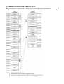
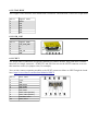
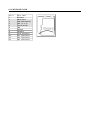
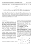
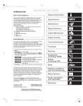
PIC32-HMZ144 General-purpose development board USER’S MANUAL Document revision B, December 2015 Designed by OLIMEX Ltd, 2015 All boards produced by Olimex LTD are ROHS compliant OLIMEX© 2015 PIC32-HMZ144 user's manual DISCLAIMER © 2015 Olimex Ltd. Olimex®, logo and combinations thereof, are registered trademarks of Olimex Ltd. Other product names may be trademarks of others and the rights belong to their respective owners. The information in this document is provided in connection with Olimex products. No license, express or implied or otherwise, to any intellectual property right is granted by this document or in connection with the sale of Olimex products. The hardware design of PIC32-HMZ144 development board is considered open source. Anyone can download the original schematics and board design files. The files describing the hardware are made with CadSoft's EAGLE PCB design software. The part of the software written by Olimex is released under GPL. However, note that the examples that we distribute are based on the libraries and projects released by Microchip. Make sure that you are acquainted with Microchip's license agreement before using, publishing, or distributing any code based on our software. It is possible that the pictures in this manual differ from the latest revision of the board. The product described in this document is subject to continuous development and improvements. All particulars of the product and its use contained in this document are given by OLIMEX in good faith. However all warranties implied or expressed including but not limited to implied warranties of merchantability or fitness for purpose are excluded. This document is intended only to assist the reader in the use of the product. OLIMEX Ltd. shall not be liable for any loss or damage arising from the use of any information in this document or any error or omission in such information or any incorrect use of the product. This evaluation board/kit is intended for use for engineering development, demonstration, or evaluation purposes only and is not considered by OLIMEX to be a finished end-product fit for general consumer use. Persons handling the product must have electronics training and observe good engineering practice standards. As such, the goods being provided are not intended to be complete in terms of required design-, marketing-, and/or manufacturing-related protective considerations, including product safety and environmental measures typically found in end products that incorporate such semiconductor components or circuit boards. Olimex currently deals with a variety of customers for products, and therefore our arrangement with the user is not exclusive. Olimex assumes no liability for applications assistance, customer product design, software performance, or infringement of patents or services described herein. THERE IS NO WARRANTY FOR THE DESIGN MATERIALS AND THE COMPONENTS USED TO CREATE PIC32-HMZ144. THEY ARE CONSIDERED SUITABLE ONLY FOR PIC32-HMZ144. Page 2 of 25 OLIMEX© 2015 PIC32-HMZ144 user's manual Table of Contents DISCLAIMER............................................................................................2 CHAPTER 1: INTRODUCTION............................................................. 4 1.1 BOARD FEATURES...............................................................................................................4 1.2 MINIMAL BOARD USE REQUIREMENTS...................................................................... 5 1.3 TARGET MARKET OF THE BOARD.................................................................................5 1.4 ELECTROSTATIC WARNING.............................................................................................6 1.5 DOCUMENT ORGANIZATION...........................................................................................6 CHAPTER 2: BOARD DESCRIPTION..................................................7 2.1 LAYOUT (TOP VIEW)........................................................................................................... 7 2.2 PINOUT....................................................................................................................................8 CHAPTER 3: BOARD SCHEMATIC AND DIMENSIONS.................9 3.1 SCHEMATIC...........................................................................................................................9 3.2 PHYSICAL DIMENSIONS.................................................................................................. 11 CHAPTER 4: PROCESSOR DETAILS................................................ 12 4.1 FEATURES............................................................................................................................ 12 4.2 MICROCONTROLLER BLOCK DIAGRAM.................................................................. 15 4.3 MICROCONTROLLER MEMORY MAP.........................................................................16 CHAPTER 5: CONTROL CIRCUITRY............................................... 17 5.1 POWER SUPPLY CIRCUIT................................................................................................17 5.2 RESET CIRCUIT..................................................................................................................18 5.3 CLOCK CIRCUIT................................................................................................................ 18 CHAPTER 6: JUMPERS, CONNECTORS AND INTERFACES......19 6.1 JUMPER DESCRIPTION....................................................................................................19 6.2 INPUT/OUTPUT................................................................................................................... 19 6.3 EXTERNAL CONNECTOR DESCRIPTION....................................................................19 6.3.1 ICSP CONNECTOR....................................................................................................................................19 6.3.2 JTAG ROW...................................................................................................................................................20 6.3.3 UEXT.............................................................................................................................................................20 6.3.4 MICROSD CARD........................................................................................................................................21 CHAPTER 7: AVAILABLE DEMO SOFTWARE................................22 CHAPTER 8: ORDERING INFORMATION AND REVISIONS......23 8.1 DOCUMENT REVISION.....................................................................................................23 8.2 BOARD REVISION.............................................................................................................. 23 8.3 USEFUL WEB LINKS.......................................................................................................... 24 CHAPTER 9: WARRANTY AND SUPPORT.......................................25 Page 3 of 25 OLIMEX© 2015 PIC32-HMZ144 user's manual CHAPTER 1: INTRODUCTION Thank you for choosing this general-purpose development board designed and assembled by Olimex LTD! This document provides a user’s guide for the PIC32-HMZ144 board. As an overview, this chapter gives the scope of this document and lists the board’s features. The document’s organization is then detailed. The PIC32-HMZ144 development board allows code development of applications running on the PIC32MZ144 processor, manufactured by Microchip Technology Inc from the U.S.A. PIC32-HMZ144 board is an open-source, open-hardware project and all documents needed to manufacture the board are available to the customer. The software code written by Olimex LTD is released under GPL. However, the examples that we distribute are heavily based on the libraries and projects released by Microchip Technology Inc, which are non-GPL. Make sure that you are acquainted with Microchip's license agreement before using, publishing, or distributing any code based on the demo software released by Olimex LTD. 1.1 BOARD FEATURES PIC32-HMZ144 board features a PIC32MZ2048ECG144 processor. It is one of the most-capable PIC32 processors ever made and it has a lot of interfaces available (6 x UARTs; 6 x SPIs; 5 x I2Cs; 120 x IO pins; 48-channel ADC; two analog comparators; Ethernet; USB-OTG; JTAG; TRACE; etc.) The board has several ready-to-use interfaces exposed and available on connectors: a microSD card connector; mini USB connector (with OTG functionality); ICSP connector for programming and debugging; UEXT connector for extension modules; user-programmable LED; userprogrammable button; 100 pinholes in two rows for measurements and access to IO processor pins; etc. The most notable board features are listed below: PIC32MZ2048ECG144 with 512KB RAM and 2MB Flash USB-OTG functionality with mini USB connector MicroSD card connector ICSP for debugging and programming JTAG pins exposed on 0.1" step 6 pins EXT1 and EXT2 50 pin 0.1" connectors that ease the access to the processor RESET and USER buttons PWR and STATUS LEDs Li-Po battery connector and charger UEXT connector Dimensions: (77×52)mm ~ (3×2)mm Page 4 of 25 OLIMEX© 2015 PIC32-HMZ144 user's manual 1.2 MINIMAL BOARD USE REQUIREMENTS • Hardware required for programming In order upload code on the board you would need a PIC32 compatible debugger or programmer. Older tools might lack support for PIC32 processor. Please ensure your programmer/debugger is compatible with the PIC32MZ processor family. The board has no bootloader loaded. You need either a debugger or a programmer tool to upload software to the board. The on-board ICSP interface is available at a 6-pin (1×6) 0.1” step connector. • Software required for programming You would need software that supports PIC32MZ family of processors. The most commonly used tool for software development for PIC32MZ applications is MPLAB X. The most used tool for binary upload to PIC32MZ is MPLAB IPE. Microchip provides a set of libraries and demo projects for the PIC32MZ family in their “Harmony Integrated Software Framework”. Note that MPLAB 8.xx does NOT support PIC32MZ. • (Optional) hardware to power the board. The board requires power supply. If your debugger/programmer is not capable of powering the board via the ICSP connector then you would need either: USB cable (1); or Li-Po battery (2); or 5V external power supply (3). (1) The USB cable should have male mini USB connector to be able to fit the board's female mini USB connector (2) The battery requires a male DW02R connector (CI0102) to fit in the on-board female DW02R connector (3) There are only pinholes available on the board. You would need wires to establish a connection between the external power supply (adapter) with the board. 1.3 TARGET MARKET OF THE BOARD PIC32-HMZ144 would attract PIC enthusiasts and veterans who want to evaluate the features of the PIC32MZ2048ECG144 processor. Any experience with the development tools required for generalpurpose development of code for boards featuring PIC32MZ boards is a great plus. The board is not suitable for complete beginners – it lacks a bootloader which means that you can't upload software via the USB. You need at least a PIC32-compatible programmer with 6-pin 0.1” step ICSP connector. In case you are a complete beginner you might want to start with a board with bootloader, like PIC32-PINGUINO-OTG or DUINOMITE. You can upload code to such boards via an USB cable. Page 5 of 25 OLIMEX© 2015 PIC32-HMZ144 user's manual 1.4 ELECTROSTATIC WARNING The PIC32-HMZ144 board is shipped in protective anti-static packaging. The board must not be subject to high electrostatic potentials. General practice for working with static sensitive devices should be applied when working with this board. The product box includes 4 rubber feet – it is recommended to place them in the holes near the edges of the board. This way the board would be safe if placed on conductive surfaces! 1.5 DOCUMENT ORGANIZATION Each section in this document covers a separate topic, organized as follows: – Chapter 1 is an overview of the board usage and features – Chapter 2 contains the general board diagram and layout – Chapter 3 provides the schematics and the dimensions of the board – Chapter 4 provides a guide for quickly setting up the board and software notes – Chapter 5 describes the component that is the heart of the board: the Microchip's PIC32MZ2048 processor – Chapter 6 is an explanation of the control circuitry associated with the processor – Chapter 7 covers the connector pinout, peripherals and jumper description – Chapter 8 contains the revision history, useful links and support information – Chapter 9 contains the warranty information Page 6 of 25 OLIMEX© 2015 PIC32-HMZ144 user's manual CHAPTER 2: BOARD DESCRIPTION 2.1 LAYOUT (TOP VIEW) The picture below shows the top side of the board and highlights the most important parts: Page 7 of 25 OLIMEX© 2015 PIC32-HMZ144 user's manual 2.2 PINOUT Page 8 of 25 CHAPTER 3: BOARD SCHEMATIC AND DIMENSIONS In this chapter you may find information about the schematics describing logically and physically PIC32-HMZ144. 3.1 SCHEMATIC The schematic of PIC32-HMZ144 is available for reference on the next page. The design files are available at our GitHub repository. Refer to chapter 8 to find the link to our repository. If you are looking for a schematic of an older revision of the board and it isn't available at our web site you may request it by the support e-mail. OLIMEX© 2015 PIC32-HMZ144 user's manual RESET,TMS,TCK 3.3V D1 1 3.3V C15 10nF RG7(E_MEASUREMENT) R1 330R JTAG PIC32-HMZ144 Designed by Olimex_LTD RESET 1N5819(S4SOD-123) ICSP RESET TCK TMS TDO TDI 2 3 4 5 RESET 1 POWER_SUPPLY RG15(V_BAT) R8 1M/1% R9 +5V 2 3M 3 5 6 64 107 122 137 VB AT 3 VDD C13 2 D3 1N5819(SS14) VDD IN 3 FB 5 AVDD41 VDD VDD EN GND R32 C37 Vout=0.6x(1+Re/Rf) R10 0R(Board_Mounted) R33 3.7V-LI_BAT 3 ISET R5 100k Iset = 6800/R68 Iset = 523mA USB +5V_OTG_PWR DD+ USB_ID GND_PIN +5V_OTG_PWR +5V_OTG_PWR DD+ USB_ID R31 54 63 89 108 123 136 VSS 75 GN D VSS VSS RESET 20 TMS TCK RA2/SCL2 RA3/SDA2 22 RA4/PMA14 RA5/PMA5 87 RA6 129 RA7 130 RA9 39 AREF 40 RA14 95 RA15 96 RB0 36 RB1 RB2(OTG_FAULT) 35 RB3 31 RB4 26 100nF VSS VSS VSS VSS VSS AREF 3.3V_AVCC R34 NA R35 NA R18 NA AREF R19 NA C FB0805 /6 00R/2A #M CLR AVSS 42 VSS USB-OTG FB1 56 85 86 2 VOLTAGE_REFERENCE R17 NA D+ ID C20 PIC32MZ2048ECG144-I/PH +5V D- NA U1_MAIN 32 VBU S VBUS 73 VDD 4 R6 13k/1% VUSB3V 74 3 17 EN 5 0R Rf DW02R IN C4 22uF/6.3V 22uF/6.3V 22uF/6.3V SY8009AAAC(SOT23-5) 2 C16 15k C3 C2 Re 27pF 3.3V VDD 1 OUT FB0805/600R/2A appr. 70 mA charge current VDD SY6280 U3 L1 L2 2.2uH/1.5A/DCR<0.1R/CD32 LX -1 PROG 5 VSS R11 VDD 2 CE 1 BATTERY CHARGER U1_PWR VDD 1 R4 10k MCP73812T-420I/OT 3.3V 88 +5V U2 3.3V_AVCC 4 55 47k FB0805/600R/2A +5V +5V 33 IRLML6402 L4 U4 4 +5V R2 RB2(OTG_FAULT) FET1 Battery Charger WF6S 18 USB_OTG RB5(OTG_EN) 3.3V_AVCC 1N5819(SS14) 6 NA(HN1X6) 3.3V D2 PGED2 PGEC2 4 SR1 R A R20 NA TMS/A N24/RA0 TCK/AN29/R A1 SCL2/RA2 EBIRDY1/SDA2/RA3 EBIA14/PM CS1/PM A14/RA4 EBIA5/AN 34/PMA 5/RA5 D+ 77 D+ D+ D- 76 D- D- EB ID11/RPF0/PM D11/RF0 124 RF0/PMD11 EB ID10/RPF1/PM D10/RF1 125 RF1/PMD10 SDA3/RPF2/RF2 79 RF2 R PF3/U 78SBID/R F3 USB_ID USB_ID 3.3V EB IA9/RPF4/SDA5/PM A9/R F4 90 RF4/PMA9 3.3V EB IA8/RPF5/SCL5/PM A8/RF5 91 RF5/PMA8 RB5(OTG_EN) 25 PGEC2 PGED2 37 RB8/PMA10 RB9/PMA7 47 RB10 49 RB11 RB12(BUT) 50 RB13 RB14/#SS2 60 RB15/#SS1 62 RC1/PMA6 RC2/PMA12 RC3/PMWR RC4/PMRD 6 38 48 59 61 3.3V 3.3V 3.3V SC L3/R 80PF8/R F8 RF8 R13 VREF-/CVR EF-/AN27/RA 9 2.2k VREF+/C VREF+/A N28/RA10 RE8/U2TX RA2/SCL2 RD14/SDI1(MISO1) RD1/SCK1 RPA14/SCL1/RA14 RPA15/SDA 1/RA15 PGED1/A N0/RPB0/R B0 PGEC1/AN 1/RPB1/RB 1 R14 R15 R16 47k 2.2k 47k UEXT TDO/AN 5831/RPF12/RF12 TDO TDI/AN30/R PF13/SC 57 TDI K5/RF13 34 UEXT TRCLK/SQICLK/RA 6 TRD3/SQID3/RA7 EB ID8/RPG0/PMD8/RG0 128 RG0/PMD8 EB ID9/RPG1/PMD9/RG1 127 RG1/PMD9 1 2 3 4 5 6 7 8 9 10 RE9/U2RX RA3/SDA2 RD15/SDO1(MOSI1) RB15/#SS1 GBH-254-SMT-10 AN2/C2IN B/RPB2/R B2 AN3/C2IN A/RPB3/R B3 AN4/C1IN B/RB4 AN45/C1IN A/RPB5/R B5 PGEC2/AN 46/RPB6/RB 6 PGED2/A N47/RPB7/R B7 EBIA10/AN 48/RPB8/PM A10/RB8 EBIA7/AN 49/RPB9/PM A7/RB9 A N14/C1IN 14 D/RPG6/SCK2/RG6 RG6/SCK2 A N13/C1IN 15 C/RPG7/SDA4/RG7 RG7(E_MEASUREMENT) A N12/C2IN 16 D/RPG8/SCL4/RG8 RG8/SDO2(MOSI2) EB IA2/AN11/C 2INC/RPG9/PM 21 RG9/PMA2 A2/RG9 CVREFOU T/AN5/R PB10/RB10 AN6/RB 11 TR D1/SQID1/RG12 140 RG12 AN7/RB 12 TR D0/SQID0/RG13 141 RG13 AN8/RB 13 AN9/RPB 14/SCK3/RB14 AN10/RPB 15/OCFB/RB 15 TR D2/SQID2/RG14 139 RG14 A N23/RG15 1 RG15(V_BAT) A N38/ETXD2/RH0 43 RH0 C2920pF 3.3V 11 12 13 R36 10k 71 C3010pF 3.3V MICRO_SD 105 106 Q2 Q1 72 EBIA6/AN 22/RPC1/PM A6/RC1 EBIA12/AN 21/RPC2/PM A12/RC2 EBIW E/AN 20/RPC3/PM W R/RC 3 EBIOE/AN 19/RPC4/PM RD/RC4 OSCI/CLKI/RC 12 SOSCI/RPC 13/RC13 SOSCO/RPC14/T1CK/RC 14 OSCO/CLKO/RC15 13 RJ5(SD_CP) 9 DAT2/RES 1 DAT1/RES 8 DAT0/DO 7 RD7/SDI2(MISO2) RG6/SCK2 C LK/SC 5 LK V DD4 V SS6 C3322uF/6.3V C MD/DI 3 C3422uF/6.3V C D/DA 2 T3/CS TFC-WPAPR-08 RG8/SDO2(MOSI2) RB14/#SS2 100k R23 3.3V 3.3V 3.3V BUTTONS LEDS R24 R25 10k 10k R26 109 110 111 118 119 120 121 RD9/PMA15 97 RD10 RD11 98 RD12/PMD12 112 RD13/PMD13 RD14/SDI1(MISO1) 113 RD15/SDO1(MOSI1) 70 99 69 RE0/PMD0 135 RE1/PMD1 RE2/PMD2 138 142 RE3/PMD3 143 RE4/PMD4 144 RE5/PMD5 RE6/PMD6 3 RE7/PMD7 5 RE8/U2TX RE9/U2RX 23 4 24 RPD0/RTC C/INT0/RD0 RPD1/SCK1/R D1 EBID14/RPD2/PM D14/RD2 EBID15/RPD3/PM D15/RD3 SQICS0/RPD4/RD4 SQICS1/RPD5/RD5 ETXEN/RPD6/RD6 ETXCLK/RPD7/R D7 EBIA15/RPD9/PMC S2/PMA 15/RD9 RPD10/SCK4/R D10 EMDC/RPD11/RD11 EBID12/RPD12/PM D12/RD12 EBID13/PM D13/R D13 AN32/RPD14/RD14 AN33/RPD15/SCK6/RD15 EBID0/PM D0/R E0 EBID1/PM D1/R E1 EBID2/PM D2/R E2 EBID3/RPE3/PM D3/RE3 EBID4/AN 18/PM D4/RE4 EBID5/AN 17/RPE5/PM D5/RE5 EBID6/AN 16/PM D6/RE6 EBID7/AN 15/PM D7/RE7 AN25/RPE8/R E8 AN26/RPE9/R E9 RH2(LED1) 330R RST R27 1k BUT C36 R28 330R C35 100nF R29 330R NA(100nF) LED1 LED/GREEN/0603 PIC32-HMZ144 3.3V_AVCC EB IA4/PM 68 A4/RH7 RH7/PMA4 ER XD0/RH 81 8 ER XD3/RH 82 9 RH8 RH9 EC OL/RH10 83 RH10 +5V 3.3V EXT1 board revision C Designed and assembled by Olimex LTD, Bulgaria https://www.olimex.com Page 10 of 25 EXT2 1 2 1 2 GND 3 4 3 4 RJ0 EB IA23/RH15 103 RH15 AREF RD2/PMD14 5 6 6 8 RD3/PMD15 RH14 RH13 5 7 7 8 RJ1 RJ2 ETX ERR/RJ0 114 RJ0 RD0 9 10 RD4 RH12 9 10 RJ3 EM DIO/RJ1 115 RC4/PMRD RC3/PMWR 11 12 14 RH11 RH10 12 13 RD5 RD6 11 EB IRDY3/RJ2 116 RJ1 RJ2 13 14 RJ4 RJ6 EB IA22/RJ3 117 RJ3 RC2/PMA12 15 16 RD9/PMA15 RH9 15 16 RJ7 EB ICS0/RJ4 131 RJ4 RC1/PMA6 17 18 RD10 RH8 17 18 RJ8 EB ICS1/RJ5 132 RJ5(SD_CP) RJ6 RB13 RB11 19 20 20 22 RH7/PMA4 RH6 19 21 RD11 RD12/PMD12 21 22 RJ9 RJ10 RJ7 RB10 23 24 RD13/PMD13 RH5 23 24 RJ11 RB9/PMA7 RB8/PMA10 25 26 26 28 RH4 RH3 25 27 RE0/PMD0 RE1/PMD1 27 28 RJ12 RJ13/PMA13 R H14 102 104 PIC32MZ2048ECG144-I/PH RB12(BUT) RESET A N41/ERXD1/RH5 66 RH5 A N42/ERXD2/RH6 67 RH6 EC RS/RH12 100 RH12 ER XDV/EC H13 101 RSDV/R RH13 MC-306_32.768KHz/6pF Q12.000MHz/HC-49S/SMD/20pF/30ppm MICRO-SD EB IRP/RH2 45 RH2(LED1) R H3 46 RH3 A N40/ERXER R/RH4 65 RH4 EB IRDY2/RH 11 RH11 84 C3110pF C3220pF RD0 RD1/SCK1 RD2/PMD14 RD3/PMD15 RD4 RD5 RD6 RD7/SDI2(MISO2) A N39/ETXD3/RH1 44 RH1 EB ICS2/RJ6 133 EB ICS3/RJ7 134 RH14 A N35/ETXD0/RJ8 7 RJ8 A N36/ETXD1/RJ9 8 RJ9 EB IBS1/RJ10 10 RJ10 GND AGND AGND +5V RH15 RB4 RB3 29 30 32 RH1 RH0 30 31 RE2/PMD2 RE3/PMD3 29 A N37/ERXC LK/ER EFC LK/R J11 27 RJ11 31 32 RJ14/PMA11 RJ15/PMA0 EB IBS0/RJ12 9 RB1 33 34 RE4/PMD4 RG14 33 34 RK0 RB0 RA15 35 36 RG13 RG12 36 38 RE5/PMD5 RE6/PMD6 35 37 37 38 RK1/PMA1 RK2/PMA3 39 40 40 42 RG9/PMA2 RG1/PMD9 39 41 RE7/PMD7 RF0/PMD11 41 42 RJ12 EB IA13/PM 28 A13/RJ13 RJ13/PMA13 EB IA11/PM 29 A11/RJ14 RJ14/PMA11 EB IA0/PM 30 A0/RJ15 RJ15/PMA0 EB IA16/RK0 19 RK0 EB IA1/PM 51 A1/RK1 RK1/PMA1 EB IA3/PM 52 A3/RK2 RK2/PMA3 EB IA17/RK3 53 EB IA18/RK4 92 RK3 EB IA19/RK5 93 EB IA20/RK6 94 RK5 RK6 EB IA21/RK7 126 RK7 RK4 RA14 RA9 RK3 RK4 RA7 43 44 RF1/PMD10 RG0/PMD8 43 44 RK5 RA6 RA5/PMA5 45 46 RF8 45 46 47 48 RF2 RF4/PMA9 RESET 47 48 RK6 RK7 RA4/PMA14 49 50 RF5/PMA8 GND 49 50 GND NA NA OLIMEX© 2015 PIC32-HMZ144 user's manual 3.2 PHYSICAL DIMENSIONS Note that all dimensions are in millimeters. Page 11 of 25 CHAPTER 4: PROCESSOR DETAILS Some of the details about the main processor in the design of PIC32-HMZ144 (PIC32MZ2048ECG144) are mentioned in this chapter. It is highly recommended to refer to the original datasheet which might be downloaded from the Microchip's official web-side. 4.1 FEATURES PIC32-HMZ144 board uses MCU PIC32MZ2048ECG144 from Microchip Technology. The main processor of the board is one of the biggest processors of the PIC32MZ family. It has the following features that distinguish it from the rest of the family: • • • • • • • • Programmable memory (KB): 2048 Data memory (KB): 512 Pins count: 144 I/O pins: 120 Reprogrammable pins: 53 ADC channels: 48 SPI/I2S interfaces: 6 CAN interface: No The PIC32MZ family of processors are 32-bit MCUs that pack the following shared features: Operating Conditions • 2.3V to 3.6V, -40ºC to +85ºC, DC to 200 MHz Core: 200 MHz (up to 330 DMIPS) microAptiv™ • 16 KB I-Cache, 4 KB D-Cache • MMU for optimum embedded OS execution • microMIPS™ mode for up to 35% smaller code size • DSP-enhanced core: ◦ Four 64-bit accumulators ◦ Single-cycle MAC, saturating and fractional math • Code-efficient (C and Assembly) architecture Clock Management • Internal oscillator • Programmable PLLs and oscillator clock sources • Fail-Safe Clock Monitor (FSCM) • Independent Watchdog Timers (WDT) and Deadman Timer (DMT) • Fast wake-up and start-up Power Management • Low-power modes (Sleep and Idle) • Integrated Power-on Reset and Brown-out Reset Memory Interfaces • 50 MHz External Bus Interface (EBI) • 50 MHz Serial Quad Interface (SQI) Audio and Graphics Interfaces • Graphics interfaces: EBI or PMP • Audio data communication: I2S, LJ, and RJ • Audio control interfaces: SPI and I2C • Audio master clock: Fractional clock frequencies with USB synchronization High-Speed (HS) Communication Interfaces (with Dedicated DMA) • USB 2.0-compliant Hi-Speed On-The-Go (OTG) controller • 10/100 Mbps Ethernet MAC with MII and RMII interface Security Features • Crypto Engine with a RNG for data encryption/decryption and authentication (AES, 3DES, SHA, MD5, and HMAC) • Advanced memory protection: ◦ Peripheral and memory region access control Direct Memory Access (DMA) • Eight channels with automatic data size detection • Programmable Cyclic Redundancy Check (CRC) Advanced Analog Features • 10-bit ADC resolution and up to 48 analog inputs • Flexible and independent ADC trigger sources • Two comparators with 32 programmable voltage references • Temperature sensor with ±2ºC accuracy Communication Interfaces • Two CAN modules (with dedicated DMA channels): • 2.0B Active with DeviceNet™ addressing support • Six UART modules (25 Mbps): ◦ Supports LIN 1.2 and IrDA® protocols • Six 4-wire SPI modules • SQI configurable as an additional SPI module (50 MHz) • Five I2C modules (up to 1 Mbaud) with SMBus support • Parallel Master Port (PMP) • Peripheral Pin Select (PPS) to enable function remap Timers/Output Compare/Input Capture • Nine 16-bit or up to four 32-bit timers/counters • Nine Output Compare (OC) modules • Nine Input Capture (IC) modules • PPS to enable function remap • Real-Time Clock and Calendar (RTCC) module Input/Output • 5V-tolerant pins with up to 32 mA source/sink • Selectable open drain, pull-ups, and pull-downs • External interrupts on all I/O pins Qualification and Class B Support • Class B Safety Library, IEC 60730 • Back-up internal oscillator Debugger Development Support • In-circuit and in-application programming • 4-wire MIPS® Enhanced JTAG interface • Unlimited software and 12 complex breakpoints • IEEE 1149.2-compatible (JTAG) boundary scan • Non-intrusive hardware-based instruction trace Software and Tools Support • C/C++ compiler with native DSP/fractional support • MPLAB® Harmony Integrated Software Framework • TCP/IP, USB, Graphics, and mTouch™ middleware • MFi, Android™, and Bluetooth® audio frameworks • RTOS Kernels: Express Logic ThreadX, FreeRTOS™, OPENRTOS®, Micriµm® µC/OS™, and SEGGER embOS® 4.2 MICROCONTROLLER BLOCK DIAGRAM A block diagram with main functional parts of the microcontroller as seen in the official Microchip documentation. 4.3 MICROCONTROLLER MEMORY MAP The microcontroller's memory regions as seen in the official Microchip documentation. CHAPTER 5: CONTROL CIRCUITRY 5.1 POWER SUPPLY CIRCUIT You have options on powering PIC32-HMZ144. You can power the board by providing: • 5V on the mini USB connector You can power the board from your personal computer via an USB cable; the USB ports of a personal computer typically provide around 5V of voltage and 500mA of current. Avoid using USB cables longer than 2 meters. Avoid the cheapest cables with high inner resistance. • (3.6 – 4.2)V on the Li-Po battery connector The board can be powered the board from a Li-Po battery with a fitting connector; a Li-Po battery typically provides between 3.6V and 4.2V of voltage. • 3.3V on the ICSP connector PIC32-HMZ144 can be powered by your debugger (programmer) tool, as long as the tool is capable of powering targets. You would need to set and enable the powering voltage to 3.3V in the software options of MPLAB. • 5V to pin 1 of the EXT2 connector The board can be powered by external power supply (adapter) capable of providing 5V of voltage. You should connect the 5V wire to pin #1 of EXT2 connector. You also need to connect the ground wire to pin #2 of the same (EXT2) connector. The names of the pins are printed at the bottom of the board. Different methods of powering would lead to different maximum current available. Consider powering the board with an external power supply connected to EXT2 if you need extra current (in case you have to power additional hardware via PIC32-HMZ144). You can have more than one power supply connected at the same time. Note that the board has built-in battery charger. If you have another power source connected to the board at the same time as the battery (for example, USB) – the charger circuit would attempt to recharge the battery. This would raise the current consumption of the whole board. With no extra peripherals connected, the board's current consumption is about 100mA at 5V when running the default demo program. 5.2 RESET CIRCUIT PIC32-HMZ144's reset signal (processor pin #20, “#MCLR”) can be found on the pads of the JTAG connector (pad #1); on the ICSP connector (connector pin #1); and it is also connect to a button. The reset circuit of the button consists of RC group R24 – 10kΩ and C35 – 100nF. Serial resistor R26 – 330Ω is used to prevent fast C35 charge and discharge when PIC32MZ2048 is being programmed. Manual reset is possible by the RESET button. 5.3 CLOCK CIRCUIT Quartz crystal Q1 12.000 MHz is connected to PIC32MZ2048ECG144's pin #71 (OSCI/CLKI/RC12) and pin #72 (OSCO/CLKO/RC15). Quartz crystal Q2 32.768 KHz is connected to PIC32MZ2048ECG144's pin #105 (SOSCI/RPC13/RC13) and pin #106 (SOSCO/RPC14/T1CK/RC14). CHAPTER 6: JUMPERS, CONNECTORS AND INTERFACES In this chapter you will find the description of the jumpers and what signals might be found on the different connectors. 6.1 JUMPER DESCRIPTION PIC32-HMZ144 has no re-configurable jumpers. 6.2 INPUT/OUTPUT User button with name BUT – connected to PIC32MZ's pin #59 (AN7/RB12). BUT can be accessed via software means. Reset button with name RST – connected to PIC32MZ's pin #20 (#MCLR). Status LED (green) with name LED1 – connected to PIC32MZ's pin #45 (EBIRP/RG2). LED1's behavior can be programmer. Power supply red LED with name PWR – indicates that 5V power supply is available. Cannot be programmed. 6.3 EXTERNAL CONNECTOR DESCRIPTION In this sub-chapter you would find the pinout of the most interfaces. It is also a good practice to refer to the latest schematic. 6.3.1 ICSP CONNECTOR The ICSP connector is used for serial programming. It is the place where most common PIC32compatible programmers and debuggers are connected. The pins have 0.1'' step. If your programmer/debugger has only the smaller 0.05'' connector you might need an adapter or you should use jumper wires. Pin # Signal name 1 2 3 4 5 6 RSTN 3.3V GND PGED2 PGEC2 NC PGED2 conducts I/O operations for the “Program Data” signal. Serial data for programming. PGEC2 serves only as input for the “Program Clock” signal. Clock used for transferring the serial data (output from ICSP, input for the MCU). 6.3.2 JTAG ROW The 6-signal JTAG interface at the board lacks a connector. The board has a JTAG row of pin holes. Pin # Signal name 1 2 3 4 5 6 RESET TCK TMS TDO TDI GND 6.3.3 USB_OTG Pin # Signal name 1 2 3 4 5 +5V_OTG_PWR DD+ USB_ID GND 6.3.3 UEXT The 10-pin UEXT connectors are typically mounted on Olimex boards. They pack three common interfaces in a single connector – UART, I2C and SPI. You can use the UEXT connector to access this interfaces easier (via jumper wires, for example). You can also connect expansion modules to the UEXT connectors. More on UEXT might be found here: https://www.olimex.com/Products/Modules/UEXT/ Pin # 1 2 3 4 5 6 7 8 9 10 Wire name 3.3V GND RE8/U2TX RE9/U2RX RA2/SCL2 RA3/SDA2 RD14/SDI1(MISO1) RD15/SDO1(MOSI1) SCK1RD1/SCK1 RB15/#SS1 6.3.4 MICROSD CARD Pin # Wire name 1 2 3 4 5 6 7 8 9 10 11 12 MCIDAT2 RB14/#SS2 RG8/SDO2(MOSI2) VDD (3.3 V) AC1TX/SCK3A GND MISO3A MCIDAT1 Card presence Not Connected Not Connected Not Connected CHAPTER 7: AVAILABLE DEMO SOFTWARE The demo project should be downloaded from the official product page of PIC32-HMZ144. The example demonstrates several features of the board: LED, Button, UART, RTC, SD card, USB. Build info (tested with): Integrated development environment: Compiler: Harmony framework: MPLABX v3.15 XC32 v1.40 v1.06.01 You can either build the project and program the board with MPLABX IDE, or use MPIPE and the prebuilt file (PIC32-HMZ144_v2.hex). It is recommended to use the same compiler if you decide to compile the project! If you want to follow the messages on the console you need to use a USB←>serial cable (like Olimex USB-SERIAL-CABLE-F or MOD-USB-RS232) to the UART pins of the UEXT (pin 3 is TX, pin 4 is RX). In order to switch between the different demos push the button. Upon reset a fast external clock test will be done to ensure that the clock is OK. After that SD card demo would start start. It will read a file on the SD card with the name: "FILE_TOO_LONG_NAME_EXAMPLE_123.JPG" (make sure you have such file in the card) The program would make a copy of that file in a sub-directory named "Dir1". The generated directory and file must not exist prior to the software test (otherwise you will receive an error). IMPORTANT NOTE: Microchip Harmony Configurator requires write protect pin but on PIC32HMZ144 board there is no such pin; the one selected by default is used (PORTF1). Since we can't set it to low level, in order to make SD card demo work properly, RF1 should be set as output in low level! If you decide to change it make sure that the new WP pin is also low! After the SD card demo is over you can see LED blinking with 1 Hz frequency controlled by the RTC oscillator. Then the USB demo gets started – the board would initialize as an USB device (mouse). When you hold the button the mouse cursor will start moving. On the terminal you can send characters and it will return echo (next symbol) followed by '*'. Microchip Harmony Configurator (MHC) requires all *.configs available in order to be initialized. But having all of them in the project would make the archive too big. So in the archive are left only the libraries that are necessary for rebuilding. So if you want to change the configurations from MHC you have to copy the project inside the Microchip harmony directory "..\apps\usb\device\" and then open the MHC from MPLABX. CHAPTER 8: ORDERING INFORMATION AND REVISIONS You can purchase directly from our online shop or from any of our distributors. Note that usually it is faster and cheaper to purchase Olimex products from our distributors. List of confirmed Olimex LTD distributors and resellers: https://www.olimex.com/Distributors. Please visit https://www.olimex.com/ for more info. Trouble finding a product mentioned above? Product name of the board discussed in this document: PIC32-HMZ144 – fully assembled and tested. Below are listed some of the related products (you can type the name of a product in the search box of our web site to find it easily): PIC-KIT3 – PIC32-HMZ144-compatible debugger, works fine with MPLAB X, MPLAB IPE. Fits the 6-pin on-board connector. USB-MINI-CABLE – a standard USB cable with type A ↔ mini connectors. BATTERY-LIPO1400 – a standard Li-Po battery equipped with a connector that fits the one located on PIC32-HMZ144. Olimex sells a range of such batteries with different capacity. JW-200x10 – jumper wires with male-male connectors and 240mm of length; perfect for breadboarding; there are different lengths and configurations of connectors (m-m; f-m; f-f). You can also find a big number of extension boards that can be connected to the UEXT of the board and also some of the components (if damage occurs and you want to replace the part yourself). Make sure to use the search box. 8.1 DOCUMENT REVISION Document revision Changes Modified page A, 12.11.15 Initial manual release All B, 14.12.15 Updated the information about the demo 22 8.2 BOARD REVISION Remember to check the schematics and the board design files to verify any differences between the different board revisions. Board revision B Notable changes Initial release of the board 8.3 USEFUL WEB LINKS Visit the links below for more information and resources for the product: • PIC32-HMZ144 official product page: https://www.olimex.com/Products/PIC/Development/PIC32-HMZ144/ • PIC32-HMZ144 at GitHub (EAGLE CAD source files): https://github.com/OLIMEX/PIC32-HMZ144 • MPLAB Harmony framework – flexible, abstracted, fully integrated firmware development platform for PIC32 microcontrollers: MPLAB Harmony page • Official Olimex forums: https://www.olimex.com/forum/index.php?board=21.0 CHAPTER 9: WARRANTY AND SUPPORT For product support, hardware information and error reports mail to: [email protected]. All document or hardware feedback is welcome. Note that we are primarily a hardware company and our software support is limited. Please consider reading the paragraph below about the warranty of Olimex products. All goods are checked before they are sent out. In the unlikely event that goods are faulty, they must be returned, to OLIMEX at the address listed on your order invoice. OLIMEX will not accept goods that have clearly been used more than the amount needed to evaluate their functionality. If the goods are found to be in working condition, and the lack of functionality is a result of lack of knowledge on the customers part, no refund will be made, but the goods will be returned to the user at their expense. All returns must be authorized by an RMA Number. Email [email protected] for authorization number before shipping back any merchandise. Please include your name, phone number and order number in your email request. Returns for any unaffected development board, programmer, tools, and cables permitted within 7 days from the date of receipt of merchandise. After such time, all sales are considered final. Returns of incorrect ordered items are allowed subject to a 10% restocking fee. What is unaffected? If you hooked it to power, you affected it. To be clear, this includes items that have been soldered to, or have had their firmware changed. Because of the nature of the products we deal with (prototyping electronic tools) we cannot allow returns of items that have been programmed, powered up, or otherwise changed post shipment from our warehouse. All returned merchandise must be in its original mint and clean condition. Returns on damaged, scratched, programmed, burnt, or otherwise 'played with' merchandise will not be accepted. All returns must include all the factory accessories which come with the item. This includes any In-Circuit-Serial-Programming cables, anti-static packing, boxes, etc. With your return, enclose your PO#. Also include a brief letter of explanation of why the merchandise is being returned and state your request for either a refund or an exchange. Include the authorization number on this letter, and on the outside of the shipping box. Please note: It is your responsibility to ensure that returned goods reach us. Please use a reliable form of shipping. If we do not receive your package we will not be held liable. Shipping and handling charges are not refundable. We are not responsible for any shipping charges of merchandise being returned to us or returning working items to you. The full text might be found at https://www.olimex.com/wiki/GTC#Warranty for future reference.