1
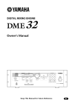
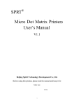
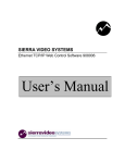
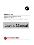
SIERRA VIDEO OG-RTR-804, OG-RTR-802, OG-RTR-404, OG-RTR402 HD/SDI Video Routing Switching Modules and OG-RTR-10, OG-RTR-20 Rear Modules User’s Manual OG-RTR HD/SDI ROUTING SWITCHER MODULE User’s Manual Sierra Video P.O. Box 2462 Grass Valley, CA 95945 Tel: (530) 478-1000 Fax: (530) 478-1105 Email: [email protected] Version 2.0 Publication Date: February 2012 The information contained in this manual is subject to change by Sierra Video © Sierra Video Table of Contents Introduction 1 Warnings & Safety Regulations Warnings Cautions EMC Regulatory Notices Delivery Damage Inspection Factors Affecting Quality of Results OG-RTR-804 2 2 2 3 3 3 4 Installation 7 Introduction Module Mounting Rear I/O Panel Video Connections Input Equalization Reclocking Connecting Peripherals Sync Connectors Remote Control Panels Control via 9-pin Connectors Control via Ethernet Serial Control Generic Protocol DashBoard Software The Menu System Product Status Control Module Settings I/O Settings Salvos Host Settings Panel Settings 7 7 7 8 8 8 9 9 10 10 11 11 11 23 23 23 24 25 26 29 32 33 34 OG-RTR Module Block Diagrams Circuit Description 35 35 36 Specifications 37 Warranty 39 SIERRA VIDEO 1 Chapter Introduction The Sierra Video OG-RTR HD/SDI Video matrix module offers a high performance solution to your video needs. The modules can be removed or re-inserted with power to the frame either on or off. The module provides equalization and re-clocking at all SMPTE SD-HD video standard data rates SMPTE-259M,292,424M (270 Mb/s, 1.485 Gb/s and 2.97 Gb/s.) User definable for the bypass of re-clocking and be able to accommodate ASI/DVB signals on the outputs. The OG-RTR accommodates ASI/DVB signals, on all outputs (noninverting). The OG-RTR-10 and OG-RTR-20 rear modules fit in the 10 and 20 slot Open Gear frame and module settings can be monitored via the Open Gear DashBoard software program. The frames provide low voltage DC input to each module. 1 SIERRA VIDEO Warnings & Safety Regulations The information in the following section provides important warnings and safety guidelines for both the operator and service personnel. Specific warnings and cautions may be found throughout this manual. Please read and follow the important safety precautions noting especially those instructions relating to risk of fire, electrical shock and injury to persons. Any instructions in this manual that require opening the equipment cover or enclosure are intended for use by qualified service personnel only. To reduce the risk of electrical shock, do not perform any servicing other than what is contained in the operating instructions unless you are qualified. Warnings Heed all warnings on the unit and in the operating instructions. Disconnect AC power before installing any options. Do not use this product in or near water. This product is grounded through the grounding conductor of the power cord. To avoid electrical shock, plug the power cord into a properly wired receptacle before connecting inputs and outputs. Route power cords and other cables so that they are not likely to be damaged, or create a hazard. Dangerous voltages exist at several points in this product. To avoid personal injury, do not touch unsafe connections and components when the power is on. To avoid fire hazard, use only the specified type, correct voltage, and current rating of fuse. Always refer fuse replacement to qualified service personnel. Have qualified personnel perform safety checks after any completed service This is an FCC class A product. In a domestic environment, this product may cause radio interference, in which case the user may be required to take necessary measures. Use the proper AC voltage to supply power to the switcher. When installing equipment, do not attach the power cord to building surfaces. To prevent damage to equipment when replacing fuses, locate and correct trouble that caused the fuse to blow before applying power. Use only the recommended interconnect cables to connect the switcher to other frames. Follow static precautions at all times when handling the equipment. Leave the side, top, and bottom of the frame clear for air convection cooling and to allow room for cabling. Slot and openings in the frame are provided for ventilation and should not be blocked. Only an authorized Sierra Video technician should service the switchers. Any user who makes changes or modifications to the unit without the expressed approval of the Sierra Video will void the warranty. Cautions 2 OG-RTR EMC Regulatory Notices Federal Communications Commission (FCC) Part 15 Information: This device complies with Part 15 of the FCC standard rules. Operation is subject to the following conditions: This device may not cause harmful interference This device must accept any interference received including interference that may cause undesirable operations. Delivery Damage Inspection Carefully inspect the frame and exterior components to be sure that there has been no shipping damage. Make sure all modules are seated correctly and have not detached during shipment. Factors Affecting Quality of Results There are many factors affecting the quality of results when signals are transmitted from a source to a destination. Signal cables — Use only the best quality cables to avoid interference and degraded signal quality and elevated noise levels. Sockets and connectors of the sources and destinations — Use only the highest quality, since "zero ohm" connection resistance is the target. Connectors should also match the required impedance (75 ohm in video) to minimize return loss. Amplifying circuitry — Must have quality performance when the desired end result is high linearity, low distortion, and low noise. Distance between sources and destinations — Plays a major role in the final result. For long distances (over 15 meters) between sources and destinations, special measures should be taken to avoid high frequency cable losses. These measures include using higher quality cables and/or adding line cable equalizing amplifiers. Interference from neighboring electrical appliances — These can have an adverse affect on signal quality. Balanced audio lines are less prone to interference, but unbalanced audio should be installed away from any main power lines, electric motors, transmitters, etc. even when the cables are shielded. CAUTION! Only an authorized Sierra Video technician can service these products. Any user who makes changes or modifications to the unit without the expressed approval of the manufacturer will void the warranty 3 SIERRA VIDEO OG-RTR-804 Power LED Ref Lock LED Factory Use Only 4 Factory Use Only Factory Use Only OG-RTR OG-RTR-10 Dual module- 10 Slot Frame Connector Not Used (Future Use) OG-RTR-20 Quad module- 20 Slot Frame 5 SIERRA VIDEO 2 Chapter Installation Introduction Installation procedures are similar for all modules covered under this manual. Exceptions, if any, have been noted in each of the following paragraphs. Module Mounting Carefully inspect the module to ensure that there has been no shipping damage. Make sure all shipping material is removed from the module and frame. Install the RTR and rear module in any available slot in the frame with the ejector tab towards the bottom. Lock the module in place with the ejector tab. Rear I/O Panel OG-RTR-10 and OG-RTR-20 The 10 slot frame uses the I/O module: OG-RTR-10. The 20 slot frame uses the OGRTR-20. These rear modules are used for all models of the OG-RTR module. 7 SIERRA VIDEO Video Connections OG-RTR-10/20 Video system interconnects are made by using 75 ohm transmission lines (coax cable). The device driving the line has a “source” impedance of 75 ohms, the cable has a 75 ohm impedance and the end of the interconnect is internally terminated with 75 ohms. The accuracy of the termination affects signal level. Use either a 1% or 0.1% termination. Unused amplifier positions do not need a termination. Only the outputs which are used need to be terminated. Input Equalization The OG-RTR Series HD/SDI 3G Routing Switchers have adjustable input equalization settings. The factory default setting for Equalization is ON. There are two states for the equalization setting - active (ON) or bypassed (OFF). Adjustment to the input equalization is made via the DashBoard software (see next section). Reclocking The OG-RTR Series HD/SDI 3G Routing Switchers also have adjustable output reclocking settings. The factory default setting for reclocking is ON (automatic). The factory default setting for reclocking is Automatic. The reclocking circuit, when in the automatic mode, will automatically detect and lock to incoming SMPTE SDI data signals. If a non-SMPTE data rate is detected, the reclocker will automatically enter the bypass mode in order to pass the signal without reclocking. There are two states for the Reclocking setting - automatic (ON) or bypassed (OFF). Adjustment to the output reclocking is made via the DashBoard software (see next section). 8 OG-RTR Connecting Peripherals Control panels and sync inputs are all connected to the rear of the frame. The peripherals area may vary depending on the model size and type. The OG-RTR-10 and the OGRTR-20 have the same connections. Remote Control Panel Connector RS-232/422 Control connector Connector Not Used (Future Use) Sync Connectors There two BNC connectors labeled "REF-1 and REF-2" on the rear of the Open Gear frame. These are “looping” inputs for sync referencing. Connect either Bi-level or Tri-level sync to either BNC. If desired, use the second “looping” BNC connector to send to another device. If the loop is not used, terminate it with 75 ohms. Selection of “REF-1 or REF-2” is made in the DashBoard software. If a video sync signal is applied to the routing switcher module, the control system will cause all switching to occur during the vertical interval of the reference. If no sync is available, the routing switcher will switch at a random point rather than during the vertical interval of the reference signal. Sync adjustments are made via the DashBoard software program (see next section). 9 SIERRA VIDEO Remote Control Panels Up to 10 remote control panels may be connected to the OG-RTR module. Sierra Video offers an extensive line of RS-485 XY and single-bus remote control panels. The connector on the rear module is a 3-pin male mini-XLR connector. The mating connectors used are Switchcraft TA3F. There are 2 connectors on the rear of the remote control panels that are connected in parallel. This allows the panels to be looped (“daisy chained”) together. If it is more convenient, you can build a fan-out panel or box so that only one cable needs to run to each panel. The maximum system cable length is 2,000 feet (310m) when the RS-485 network operates at the higher speed of 31.25K baud. The maximum system cable length is 5,000 feet (1,524m) when operated at 9600 baud. Consult your Control Panel Manual for more detailed information. If you make your own interconnect cables, Pin 2 is Ground. Pin 1 and 3 connect pin for pin. Control via 9-pin Connectors The 9-pin connector on the rear module allows you to control the routing switcher via an external computer. On some switcher models, the serial port can be changed internally for RS422 configuration (RS232 @ 9600 baud is factory configuration). Each routing switcher model has one port and it is labeled on the back panel as “RS232/422 Control” (refer also to the illustrations of back panels shown in Chapter 1): Connection to the RS-232/422 port is made using a standard 9 pin (pin to pin) cable. RS-232 pinout; Pin 2……….TX Pin 3……….RX Pin 5……….GND NOTE: To convert the 9-pin connector to an RS422 serial port, contact Sierra Video. 10 OG-RTR Control via Ethernet The matrix switcher module may be controlled via Ethernet using the DashBoard software (see next section). Serial Control The RS-232/422 serial control port supports baud rates of 9600, 38400, and115200. RS-232 pinout; Pin 2……….TX Pin 3……….RX Pin 5……….GND Generic Protocol Commands are sent to a routing switcher in a group called a command string. A command string can contain zero or more commands, limited only by the size of the receive buffer of the router, whose size depends on the particular router model. A command string consists of a leader string of asterisk characters, zero or more commands, and a trailer string of exclamation marks. Larger Routing Switchers require two leader (**) and trailer (!!) characters, while small Routing Switchers require only one, in order to make the protocol compact for those Routing Switchers. The remainder of this document gives examples using doubled characters. Note that two leader/trailer characters may be sent to small Routing Switchers even when only one is required, and they will still work fine. If a leader character (**) is encountered within a command string being processed by a router, the string up to that point is discarded and a new command string is expected. This ensures that a router will always act on a complete command string sent to it, even if the previous one was never completely received. When a command string is received, it is not acted upon (but rather, is merely buffered up) until the final trailer character (!) character of the command string is received. At that time, the routing switcher begins to execute the commands within the string. The protocol uses only 7-bit ASCII characters. The 8th bit of received characters is treated as if it is 0. Within the command string, certain ASCII characters may be present and are ignored: any ASCII character whose code is less than the SPACE character (includes all control characters and the SPACE character) and the DEL (ASCII 7F) character. Alphabetic characters within the command string may be in either upper-case or lower-case letters. The router always sends upper case characters, except for character strings such as input, output, and level names, which may have lower case characters in them. When sending commands to the router, SPACE characters are optional, but if used may only appear before and after each individual command and NOT embedded within an individual command. Within command strings sent from the router, a single SPACE character appears before and after each individual command. SPACES may also appear in character strings. After the command string has been executed, the routing switcher returns the string " OK " (with a single space character before and after the word "OK"), followed by a string of trailer characters (exclamation marks) and a CR (carriage return, ASCII 0D) character, to the host. This indicates that the command has executed successfully. If an error occurs within any command of a command string, the remainder of the command string is ignored and the router returns the string " ERROR ", followed by an optional descriptive 11 SIERRA VIDEO string followed by a string of trailer characters and a CR character, to the host. An error can be caused by an unknown command name or bad arguments to a command. The simplest possible command string would be: **!! which consists of the leader and trailer characters but no commands between them. This command string would generate the response: ** OK !!<CR> This can be useful for verifying that the serial link to the router is operational. In Routing Switchers requiring only one leader/trailer character, the simplest command string would be: *! which would generate the response: * OK !<CR> (To determine whether a particular router uses one or two leader/trailer characters, send it "!!**" and check the response to see which of the above two responses it is. It won't hurt to always use two even if only one is required.) The simplest error response is one with no optional descriptive string. For example, this command string: ** XXX !! might generate this response from the router: ** ERROR !! Beginning with version 5.01 of the Tahoe/Sierra/Yosemite router software, a descriptive text string was added following the word "ERROR", to help with diagnosing the error. For example, the above command string might generate this response from a router running this newer software: ** ERROR Syntax:No Number:XX !! The descriptive string always ends with a colon and up to three characters from the command string that caused the error. Generally, the error can be assumed to have occurred just before these characters. 12 OG-RTR The following commands are supported; Response What it Does Syntax Example Command I **I!! I Command capabilities. Q **Q!! Q L **L!! S **S!! O out **O3!! N in **N2!! CLEAR **CLEAR!! V out,in,in... **V3,1,2,2!! X out,in,lvl **X12,9,2!! Y out,in **Y1,7!! T reg **TB!! L V, Y, or X commands V, Y, or X commands V, Y, or X commands V, Y, or X commands V, Y, or X commands V, Y, or X commands V, Y, or X commands V, Y, or X commands Model name and version. Matrix size and level names. Matrix status. Output status. Input status. Set all outputs to input 1. Connect specified inputs on each level. Connect specified input to output on level. Connect specified input to output on all levels. Trigger a salvo connect sequence. "I": Capabilities Inquiry From Syntax Host I Description Ask router to send a list of commands that are available. Available commands. (Stuff inside [] is Router I[B][C][D][F][G][H][K][L][M][N][O][P][Q][R][S][T][U][V][W][X][Y][Z]~ optional depending on router) The command "I" requests that command capability information be returned to the host. The information is sent as a string of characters. The first characters are a space followed by "I", the next characters are the letters of the commands that are implemented and available in this router, and the last character is "~" (tilde). Do not count on the characters being in any specific order. Search all characters for a particular one. All routing switchers implement the I, L, S, Q, and X commands. For example, the command: **I!! might return the following string: ** ILSX~ OK !!<CR> 13 SIERRA VIDEO indicating that the router supports the I, L, S, and X commands from the host. "Q": Model Name and Software Version Inquiry From Syntax Description Host Q Ask router to send the model name string and software version number string. Router Qmodel~version~ Model name string and software version number string. The command "Q" requests that the router model name and software version number string be returned to the host. The information is sent as a string of characters. The first characters are a space followed by "Q", the next characters are the router model name, terminated by a "~" (tilde). Following this are the characters of the software version number string, again terminated by a "~" (tilde). For example, the command: **Q!! might return the following string: ** QSmall~V2.1~ OK !!<CR> indicating that the router model name is "Small" and the software version number is "V2.1". "L": Matrix Size and Level Names Inquiry From Syntax Description Host L Ask router to send router matrix size, level names, and level information. Matrix size, level names, Router L[O[(#,#...)]][S[(#,#...)]][P[(#[=#][M][L],...)]]Nout,Nlvl,Nin,lvl1~lvl2~...lvlN~~ and level information. The command "L" requests that matrix size (Nout, Nlvl, Nin) and level name information (lvl1, lvl2, etc.) be returned to the host. The information is sent as a string of characters. The first characters are a space followed by "L", some optional values described below, then the number of outputs (Nout), a comma, the number of levels (Nlvl), a comma, the number of inputs (Nin), a comma, and then the level names, each terminated by a "~" (tilde), and the last followed by two tildes. Routers can provide names for inputs, outputs, and levels. The number of characters in a name can vary depending on the router model. The "L" command provides access only to level names, and furthermore, it truncates any level name that is longer than 6 characters to only 6 characters, in order to retain compatibility with older routers and controlling devices that limited level names 14 OG-RTR to 6 characters. Refer to the "G" command for accessing input and output names and full-length untruncated level names. The number of level names in the "L" command will be the same as the number of levels that was given in the response (Nlvl). Valid characters for level names are any printable (i.e. non-control) ASCII character (including SPACE) except "*" (asterisk), "~" (tilde), and "!" (exclamation mark). The number of characters reported by the "L" command in level names may be no more than 6 (longer names are truncated when reporting them with "L"). In systems that do not support naming of levels, the level names will be fixed number strings, e.g. "1", "2", etc. For example, the command: **L!! might return the following string: ** L64,3,32,VIDEO~AudioL~AudioR~~ OK !!<CR> indicating that the router has 64 outputs, 3 levels, and 32 inputs, and the levels are named "VIDEO", "AudioL", and "AudioR". Some routers can have different sized matrices on each level. However, the "L" command always reports what is referred to as the "basic router size". This is the size of the largest levels in the router. For example, a 2-level router with level 1 being 16x32 and level 2 being 32x16 would report a basic router size of 32x32 in the "L" command. In these kinds of routers, it is not considered an error to send a crosspoint command that specifies an all-levels take using an input or output number that is beyond the range of some of the levels, as long those numbers lie within the basic router size. Levels which are smaller than the specified numbers will not be affected by such a take command. On the other hand, it is an error to send a crosspoint command that specifies a take on a specific level with an input or output number that is beyond the range of that level. To find out the actual physical size of each level, use the "G LEVEL_INFO" command. Routers that do not support the "G" command or "G LEVEL_INFO" subcommand always have the same-size crosspoint matrix on each level. Some routers support virtual-to-physical mapping. These virtual-mapped routers use the same virtual matrix size for each level, and it will be that size that is reported in the "L" command for Nout and Nin. The physical crosspoint matrices can still be different sizes, and the "G LEVEL_INFO" command can be used to find out what these sizes are, but they are of less importance in a virtual-mapped router, because take commands are specified using virtual source and destination numbers rather than physical input and output numbers. "S": Status Inquiry From Syntax Description Host S Ask router to send source status of all router outputs. Router Y out,in or V out,in,in... or X out,in,lvl Status of all outputs connected on one or more levels to the specified input. The command "S" requests that matrix status information be returned to the host. The status information is sent as a sequence of "Y" and/or "V" and/or "X" commands. The order of the commands is not significant, and different models of routers may send the status of their outputs 15 SIERRA VIDEO in different orders. Each command string contains the output number and either a level number or data for all levels, so the order in which the status data is sent is not really important. For example, the SVS Tahoe Series routers first send one or more commands that give the status for all levels of output 1, then send commands giving status for all levels of output 2, etc. Other routers may send commands in a different order: first for all outputs of level 1, then for all outputs of level 2, etc. The "Y", "V", and "X" commands are formatted exactly as with the "O" command. Refer to the "O" command description for information about whether the router sends status using only "X" commands, or "Y", "V", and "X" commands. A 2-level 16-output router could generate as many as 2 x 16 = 32 "X" commands of status output. For example, the command: **S!! might have the following four "X" commands at the beginning of its Response: ** X1,23,1 X1,3,2 X2,-,1 X2,0,2 This indicates that output 1 is connected to input 23 on level 1, output 1 is connected to input 3 on level 2, output 2 is unconnected on level 1 (as indicated by the dash for the input number), and output 2 either does not exist or is not available on level 2 or its connection is unknown (as indicated by the zero input number). Or, the router might instead use the V command. For example: ** V1,23,3 V2,-,0 Indicating the same as the previous example. If the router has only one level, or if all levels are connected the same, it might instead use the Y command. For example: ** Y1,23 Y2,This indicates that output 1 is connected to input 23 and output 2 is unconnected. Routers that are unmapped port units will produce symmetrical status output, i.e. if there is a Y01,23 command, there will also be a Y23,01 command. "O": Output Status Inquiry From Syntax Description Host O out Ask router to send source status for all levels of specified output. Router Y out,in or V out,in,in... or X out,in,lvl Source status of the specified output. 16 OG-RTR The command "O" requests that matrix status information for a single output be returned to the host. The status information is sent as a "Y" command or a "V" command or as a sequence of L "X" commands, where L=number of levels. Whether a "Y", "V", or "X" command is sent depends on several factors: Very old routers only supported the "X" command. Routers with pre-version-10 software supported all three commands, "Y", "V", and "X", but usually provided a DIP switch that could be set to force the router to only send "X" commands. Routers with version 10 or later software use the setting of the "U" command (described below) to determine whether to send only "X" commands, or "Y", "V", and "X" commands. A 6-level router using only "X" commands could generate as many as 6 "X" commands of status output. The first command is for level 1, the next for level 2, etc. until the last level is reached. (However, each "X" command contains the level number, so the sequence in which the data is sent is not really important.) When a router is able to send "Y", "V", and "X" commands, a "Y" command will typically be sent if the router has only one level, and may also be sent if the output has all of its levels connected the same, although this is not required and some routers may instead send a "V" command or a series of "X" commands in that situation. A "V" command will be sent when an output has different connections on different levels, which is a more compact representation of the status than a series of "X" commands. The length of a "Y" or "V" or "X" command depends on the size of the particular router involved. Larger routers use longer numbers for inputs, outputs, and levels. A space character precedes each "Y" or "V" or "X" command (spaces should be ignored by the command parser, however). Each command begins with the command letter, a Y or V or X, followed by the output number and a comma character. Following that, the "Y" command has the input number connected to the output, the "V" command has L input numbers separated by commas (L=number of levels) in order by level number, and the "X" command has the level number at which the input-output pair is connected. The input number may be a dash ('-') if no connection exists (for routers that are capable of having their inputs disconnected). The input number may be 0 if the output doesn't exist at that level in the router (or isn't mapped to a physical output, in virtual-mapped routers), or if the connection is not known by the controller, as may be the case for some control panels immediately after they are powered up. For example, the command: **O5!! to a 3-level router might have the following three commands as its Response: ** X65,23,1 X5,-,2 X5,0,3 !! Note the dash, indicating that on level 2, output 65 is not connected to an input. Also note the 0, indicating that the connection on level 3 is either unknown or that output 65 doesn't exist or isn't mapped on level 3. Or, a 3-level router might have the following single command as its Response: 17 SIERRA VIDEO ** V65,23,-,0 !! which has the same information as the three X commands in the previous example. If the router has only one level, or if all levels are connected the same, the router might instead use the Y command. For example: ** Y65,23 !! The number of digits used for each number depends on the router. Newer routers use the minimum number of digits necessary, i.e. there are no unnecessary leading zeroes in a number. Older routers use the maximum number of digits ever required for an input or output number on that particular router (e.g. a router with between 10 and 99 inputs would use two digits for the input number). "N": Input Status Inquiry From Syntax Description Host N in Ask router to send status of outputs connected on one or more levels to the specified input. Router Y out,in or X out,in,lvl Status of all outputs connected on one or more levels to the specified input. The command "N" requests that matrix status information for a single input be returned to the host. The status information is sent as one or more "Y" and/or "X" commands. This command works by identifying all outputs that connect to the specified input on any level, and then generating "Y" and "X" status commands to report the status of those outputs. The "Y" and "X" commands are formatted exactly as with the "O" command. For any given output connected to the input, a "Y" command is used if the output is connected to the input on all levels, else "X" commands are used on all levels on which the input is connected to that output. Prior to version 10 software, this command was only useful on those router levels that allow an input to be connected to at most one output, and status commands were only sent for such levels. Beginning with version 10 software, a response is generated for all outputs connected to the specified input on any level, regardless of how many outputs that might be, and regardless of whether the level allows only one output connection or many output connections. For example, the command: **N4!! to a router might have the following commands as its Response: ** X12,4,1 X12,4,2 X12,4,3 X13,4,4 Y23,4 !! showing that input 4 connects to outputs (12,12,12,13) on levels 1-4, and to output 23 on levels 14. Note that a "V" command is never used in the response, unlike an "O" request described above. This is because the "V" command specifies inputs connected to an output, not outputs connected to an input. 18 OG-RTR "CLEAR": Clear Matrix From Syntax Description Host CLEAR Ask router to clear all router outputs. Router (None) All outputs are unlocked, input secures are unsecured, and all outputs are either disconnected or connected to input 1. The command "CLEAR" requests that the switch matrix be cleared so that all outputs are disconnected from inputs (in routers where this is possible) or else all outputs at all levels have input #1 as their source (when disconnecting is not possible). If output locks are supported, all output locks are removed by this command. If input security is supported, all input secures are removed by this command. This command can take several seconds to execute (depending on the size of the switch matrix), and therefore the OK response at the end of the command string could be quite late. In order to help ensure that this command isn't accidentally executed, it requires four additional characters following the "C" character, to spell out the word "CLEAR" in full. For example, the command: **CLEAR!! would clear the matrix, and when finished, the following response would be generated: ** OK !!<CR> "V": Connect Levels From Syntax Description Host V out,in,in... Make a connection to an output on each level. (None or V/Y/X command, depending on Router which "U" command argument is in effect, Optional status response. see "U" command description.) The command "V" is used to request that a connection be made. It must be followed by an output number, a comma, and a comma-separated list of input numbers, one for each level, up to the number of levels in the router. Fewer than the number of levels may be specified if desired, and the remaining levels will be left unchanged. For example, the command: **V12,7,8,9!! says that connections are to be made to output 12: from input 7 on level 1, input 8 on level 2, and input 9 on level 3. An input number of 0 means the output connection is to be left unchanged. An input number of '-' (dash) means the output is to be disconnected. If the router does not support disconnected outputs, the output connection will be left unchanged. 19 SIERRA VIDEO Unless otherwise noted in the documentation for a specific switcher, it can be assumed that the switcher software guarantees to send all level changes associated with the "V" command's output to the crosspoint matrix within the SAME vertical interval. If the requested connection has an output number that does not exist on one or more levels, those levels are simply not changed. It is an error to request connection of an input that doesn't exist on that level, even if the input does exist on some other level. If the requested connection has an output or input number that isn't mapped to a physical connector (on virtual-mapped routers) on one or more levels, those levels are simply not changed. If "U2" is in effect (see "U" command), the response will include one or more V, Y, or X commands to report the new status of the output. The response will be the same as if an "O" command were issued for the output immediately following the "V" command. No response is generated if this command is being used to define a salvo. "X": Connect Crosspoint From Syntax Description Host X out,in,lvl Make a connection to an output on a level. (None or V/Y/X command, depending on Router which "U" command argument is in effect, Optional status response. see "U" command description.) The command "X" is used to request that a connection be made. It must be followed by an output number, a comma, an input number, a comma, and a level number. For example, the command: **X24,13,2!! says that a connection is to be made between output 24 and input 13 on level 2. If the level number is specified as "0", this means that the connection is to be made on all levels (AFV). For example, the command: **X8,3,0!! says that a connection is to be made between output 8 and input 3 on all levels. An input number of 0 means the output connection is to be left unchanged, not very useful in an "X" command. An input number of '-' (dash) means the output is to be disconnected. If the router does not support disconnected outputs, the output connection will be left unchanged. When a level number of 0 is used with the "X" command, it can be assumed that the switcher software guarantees to send all level changes for the output to the crosspoint matrix within the SAME vertical interval, unless otherwise noted in the documentation for a specific switcher. It is an error to request connection of an input or output that doesn't exist on the specified level, even if it does exist on some other level. However, if the level number is "0", any input or output number may be specified as long as it exists on at least one level, and in that case no connection 20 OG-RTR will be made on any level on which the input or output does not exist. If the requested connection has an output or input number that isn't mapped to a physical connector (on virtual-mapped routers) on one or more levels, those levels are simply not changed. If "U2" is in effect (see "U" command), the response will include one or more V, Y, or X commands to report the new status of the output. The response will be the same as if an "O" command were issued for the output immediately following the "X" command. No response is generated if this command is being used to define a salvo. "Y": Connect AFV From Syntax Description Host Y out,in Make a connection to an output on all levels. (None or V/Y/X command, depending on Router which "U" command argument is in effect, Optional status response. see "U" command description.) The command "Y" is used to request that a connection be made. It must be followed by an output number, a comma, and an input number. The connection is made on all levels (AFV). For example, the command: **Y2,29!! says that input 29 is to be connected to output 2 on all levels. An input number of 0 means the output connection is to be left unchanged, not very useful in a "Y" command. An input number of '-' (dash) means the output is to be disconnected. If the router does not support disconnected outputs, the output connection will be left unchanged. Unless otherwise noted in the documentation for a specific switcher, it can be assumed that the switcher software guarantees to send all level changes for the "Y" command's output to the crosspoint matrix within the SAME vertical interval. Any input or output number may be specified as long as it exists on at least one level. No connection will be made on any level on which the input or output does not exist. If the requested connection has an output or input number that isn't mapped to a physical connector (on virtualmapped routers) on one or more levels, those levels are simply not changed. If "U2" is in effect (see "U" command), the response will include one or more V, Y, or X commands to report the new status of the output. The response will be the same as if an "O" command were issued for the output immediately following the "Y" command. No response is generated if this command is being used to define a salvo. 21 SIERRA VIDEO "T": Trigger a Salvo Connect Sequence From Syntax Description Host T reg Trigger a list of connect commands stored in a salvo register. Router (None) The command "T" is used to trigger a previously set up salvo (set using the "P" command above). It must be followed by a register letter from A to Z or a register number from 1 to 256 giving the register to be triggered. For example, the command: ** TB D180 TC !! says to trigger salvo register B (same as 2), delay 180 sync intervals, then trigger salvo register C (same as 3). When the register is triggered, this means that the connect commands stored in it take effect. If a salvo is triggered and it attempts to connect a locked output or port, or a disallowed input/output pair, or a port to itself, the salvo trigger operation is aborted, no crosspoint changes are performed, and an error is reported: "ERROR Salvo Has Locked Xpts". 22 OG-RTR DashBoard Software The DashBoard Control System enables you to monitor and control openGearTM frames and controller cards from a computer. The DashBoard software and manual can be downloaded from the Sierra Video website (www.Sierravideo.com). Using the Menus and Menu Descriptions You must first install the DashBoard Control System software on your computer. Refer to the DashBoard User Manual for software installation procedures and for using the DashBoard interface. The Menu System The following table describe the menus, items, and parameters available from the DashBoard Control System software for the module. Product Menu Module Info Product Tab (Read Only) Menu Module Info Status Tab (Read Only) Item Product Supplier Serial Number Board Revision Software Revision Item Total Power (W) Board Alarms Parameters RTR-xxx Sierra Video ##### ##### #### Parameters Power Consumption of the +12V Supply Alarm Status 23 SIERRA VIDEO Status The Status tab indicates the switching status as well as the input status of the OG-RTR. Changes cannot be made from this window. 24 OG-RTR Control Switch the routing switcher by selecting the desired source to the desired destination. Fire Salvos by clicking on the “Fire” button. 25 SIERRA VIDEO Module Settings User defined fields; Module Name ExtensionRouter NameLevel NameConfiguration fields; Take Button Enable- Placing a check in this box enables a “Take” button on the Control screen. If no check is placed in the box, the routing switcher will “Take” when a source is selected. Reference Select- Select the reference input connector to be used. Reference Format- Select the signal type (resolution) of the reference signal. 26 OG-RTR Reference Frame Rate- Select the frame rate of the reference signal. You should not use a higher frame rate for the reference signal that the frame rate of the input video or the switch will take place in the middle of the video field. Video Format- Select the video format of the video the reference signal will be applied to. That is, the format of the video to be switched. Video Frame Rate- Select the frame rate of the video to be switched. Switch Line/ Fine Adjust- The line at which the video will switch and where in the line (fine adjust) is selected in this window. 27 SIERRA VIDEO Typical switching lines when reference and video output are the same. Signal Type Switch Line SDI- NTSC 10 SDI- PAL 6 HD-1.5G and 3G 7 28 OG-RTR I/O Settings Configure Destinations Name- A user definable name can be entered in this window. There is an 8 character limit to names. 29 SIERRA VIDEO Reclocker- The reclocking rate of the output signal is selected in this window. Auto= the clock rate of the input signal. Auto= The output reclock rate is set automatically Off= No output reclocking SD, HD, 3G= Force output reclocker to rate selected. Alarm Mode- The Alarm indication that shows on the status window is selected in this window. If the output signal is not locked; Ignore= no change in the Dest Alarm (Green). Warning= the indicator will show Yellow. Alarm= the indicator will show Red. Configure Sources Name- A user definable name can be entered in this window. There is an 8 character limit to names. EQ Enable- Placing a check enables the automatic cable EQ for long cable lengths. 30 OG-RTR Alarm Mode- The Alarm indication that shows on the status window is selected in this window. If the input signal is not present; Ignore= no change in the Dest Alarm (Green). Warning= the indicator will show Yellow. Alarm= the indicator will show Red. 31 SIERRA VIDEO Salvos The current switch configuration of the routing switcher can be saved by selecting “Save”. Set up the switch, enter a name, and select “Save”. You will be prompted to Save the Salvo Yes/No after selecting “Save”. If no change is to be made to the output, select “No Change”. No Change is not a disconnect. 32 OG-RTR Host Settings The Serial port settings are made in this window. 33 SIERRA VIDEO Panel Settings This screen sets up remote control panels. Each remote control must have its own unique ID number (see the control panel manual for details). Enable destinations by placing a check in the box(s). Alarm Mode- The Alarm indication that shows on the status window is selected in this window. If the remote control panel is not present or becomes unable to communicate; Ignore= no change in the Dest Alarm (Green). Warning= the indicator will show Yellow. Alarm= the indicator will show Red. 34 SIERRA VIDEO 3 Chapter OG-RTR Module Block Diagrams 35 SIERRA VIDEO Circuit Description Please refer to the Block Diagram and the schematic, 430004-00, when reading the circuit description. This board is a simple serial digital video switch that can operate with inputs from 270Mb/s to 3Gb/s. The board uses two slots in a ten slot openGear frame and 4 slots in a 20 slot openGear frame. It will switch on the correct line in the vertical interval if a color black reference is present at one of the two reference inputs on the rear of frame. The user must use DashBoard to select which one of the two references to use and the user must also set the format of the reference and the format of the video that is being switched. The reference and video formats must have the same frame rate or have frame rates between the reference and video that have a ratio of either 1:2 or 2:1, i.e. 25Hz frame rate reference with a video frame of 50Hz. The switch point defaults to the mid line, 50%, point and can be adjusted +/- 2 lines, 1%-99% of the line using DashBoard. There is one assembly used for all four versions of this product. The veresions are: 8X4 8X2 4X4 4X2 The 8X4 is the fully loaded version and uses all inputs and all four outputs. By deleting input EQ's and Output Drivers along with their Re-clockers any of the versions can be created. Besides the DashBoard application that controls the crosspoint routing there is also a 3 pin mini XLR connector , RS-485, for a control and a 9 pin "D" connector, RS422/232, for serial control. The block diagram is on the following page and gives a high altitude view of the functions in the board. The block diagram as shown represents a 8X4 router. All eight inputs are received by an auto equalizing input stage that compensates for loss in the connecting cable. The equalization can be bypassed on an input by input baisis. This may be necessary if the user wishes to use the router with DVB-ASI inputs. Each EQ sends a carrier detect signal to the processor so that the user will get an indication of no input signal in DashBoard. The output of the EQ stage is differential and sent to an 8X8 crosspoint. Since this router has a maximum of four outputs only four outputs are used from the 8X8 crosspoint. The first four unused outputs of the crosspoint are used in a silent switch version of this product with the last four outputs from the crosspoint used as a bypass around the silent switch. In this product the last four crosspoint outputs are used for the video path full time by select them at the input of the re-clockers 2 to 1 input mux. All the no connects, NC, are connections to the unused silent switch. The outputs from the crosspoint are differential into the re-clockers. Each re-clocker is controlled through a SPI interface and can be used to bypass the re-clocking, set the reclocker to auto determine signal data rate or manually set data rate. The differential output of the re-clocker is internally terminated in 50 ohms with the destination of the output terminated differentially in 50 ohms. Each output stage drives one output BNC at the rear of the frame. There is no signal inversion from input to output. This is necessary in order to pass DVB-ASI signals. 36 SIERRA VIDEO 4 Chapter Specifications Video Data Rates 19Mbps – 2.97Gbps Data Types SMPTE 424, 372M, 310M, 259, 344M, 292M, DVB-ASI, ITU-R BT.601 Alignment Jitter < 0.2 UI, 100KHz HPF INPUT Level 800mV p-p +/-10% Nominal Connector Type BNC Impedance 75 Ohm Return Loss <-15dB- 5 MHz to 1.5 GHz, <-10dB 1.5Ghz to 3 GHz Cable Equalization SD > 300 meters for SMPTE 259M‐2008, cable Belden 1694A HD, 3G >100 meters for SMPTE 292‐2008, 424M‐2006, cable Belden 1694A OUTPUT Level 800mV p-p +/-10% Connector Type BNC Impedance 75 Ohm Return Loss <-15dB- 5 MHz to 1.5 GHz, <-10dB 1.5Ghz to 3 GHz < 1.5 ns, >0.4ns for SD 270 Mbps Rise/Fall Times ≤ 270 ps for HD 1.5Gbps ≤ 135 ps for HD 3Gbps 37 SIERRA VIDEO 5 Chapter Warranty A. General Buyer assumes all responsibility for ascertaining the suitability of Sierra Video (hereinafter "SVS") products for Buyer's intended use. No product sold by SVS is designed or manufactured for use in any manner or under any conditions other than those described in SVS's instruction manuals and other printed material for each particular product. If any product is used or applied in a manner or under conditions not specifically authorized by such written materials or if any product is used by unqualified or improperly trained personnel, Buyer agrees that SVS shall have no liability of any kind arising from such use, and Buyer agrees to indemnify and hold SVS harmless from any claims of third parties arising from such use, and Buyer shall provide SVS with counsel of SVS's choice to defend against such claims. B. Limited Warranty 1. This warranty applies only to the original purchaser and is non-transferable. This warranty begins on the date of purchase and will be in effect for five (5) years for new equipment or and for three (3) years for "Factory Refurbished" equipment. Power Supplies and fans are warranted for three (3) years from the date of purchase for new equipment and two (2) years for “Factory Refurbished” units, from the date of purchase. Buyer must obtain a Return Material Authorization ("RMA") number from SVS prior to returning a product for repair. If, in SVS' sole discretion, the product is found to be defective during the term of this warranty, SVS will at its option: (a) provide free replacement parts, and/or (b) repair the unit at an SVS facility. During the warranty period, SVS will make every reasonable effort to support critical emergencies by supplying no-cost loan equipment while the defective unit is being repaired. SVS will provide replacement parts and/or factory service at no charge. Buyer bears the cost of shipping products returned to SVS under this warranty. SVS will bear the cost of shipping repaired products or replacement parts to the Buyer. This limited warranty shall not apply to any of SVS's goods which have been altered or which shall have been subjected to misuse, mishandling, improper storage or negligence. The aforementioned provisions do not extend the original warranty period of any goods which have been replaced by SVS. This limited warranty shall not apply to any goods not of SVS's manufacture, Buyer to be entitled only to the warranty set forth in the original manufacturer's limited warranty. 39 SIERRA VIDEO THIS LIMITED WARRANTY IS EXPRESSED IN LIEU OF ALL OTHER WARRANTIES, EXPRESS, IMPLIED OR STATUTORY, INCLUDING WITHOUT LIMITATION THE IMPLIED WARRANTIES OF MERCHANTABILITY AND OF FITNESS FOR A PARTICULAR PURPOSE, AND ALL OTHER OBLIGATIONS OR LIABILITIES ON SVS'S PART. SVS neither assumes nor authorizes any other person to assume for SVS any other liabilities in connection with the sale of products of its own manufacture. 2. SVS's liability hereunder on any claim of any kind, except as set forth herein for any loss, injury to person or property or damage, shall in no case exceed the price allocable to the goods which give rise to such claim. 3. In no event shall SVS be liable for any damages or injuries to person or property if any goods do not meet the above limited warranty, including, without limitation, incidental expenses or consequential or special damages, except as set forth in such limited warranty. The foregoing states the exclusive remedy of Buyer and the exclusive liability of SVS for any breach of the foregoing limited warranty. C. Cancellation Except as provided in paragraph B immediately above, all sales are final, and Buyer may cancel this order or return products only upon written consent of SVS. D. General A. In the event of a breach of any of the terms hereof, the non-breaching party shall be entitled to recover all of its costs, fees, and expenses, including, without limitation, reasonable attorney's fees, from the breach party incurred as a result of such breach, regardless of whether or not a suit is actually filed to enforce the terms hereof. B. The provision hereof shall be governed by the laws of the State of California (excluding its choice of law provisions). C. The headings are for convenience only and do not limit or amplify the terms and provisions hereof. D. In case any one or more of the provisions set forth herein shall be held to be invalid, illegal, or unenforceable in any respect, the validity, legality, and enforceability of the remaining provisions contained herein shall not in any way be affected or impaired thereby. E. No waiver, alteration, or modification of any of the provisions hereof shall be binding unless in writing and signed by an authorized Officer of SVS. NOTE: All products returned to SVS for service must have prior approval. Return authorization requests may be obtained from your SVS dealer. 40