1
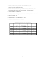
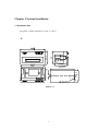
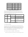
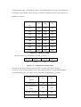
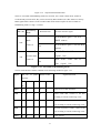
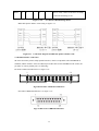
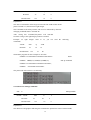
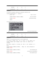
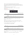
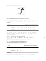
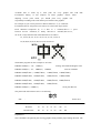
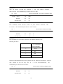
®
SPRT
Micro Dot Matrix Printers
User’s Manual
V1.1
Beijing Spirit Technology Development Co, Ltd.
Before using this product, please read the manual and keep it for
later use
2010.6
1
File version description
Date
Version
Amended content
2008
V1.0
/
2010
V1.1
Add content of DVII series
2
Content
Content ............................................................................................................................................. 3
Product brief..................................................................................................................................... 5
Chapter 1 Feature and Performance .............................................................................................. 6
1.1 Features .............................................................................................................................. 6
1.2 Performance Index.............................................................................................................. 6
Chapter 2
System Installation.................................................................................................... 8
2.1 Installation Dimension........................................................................................................ 8
A model diagram2-1 ...................................................................................................... 8
T model diagram 2-2...................................................................................................... 9
C model diagram 2-3 ..................................................................................................... 9
DN model diagram 2-4 ................................................................................................ 10
DⅦmodel diagram 2-5 ................................................................................................ 10
2.2 Paper Roll Installation .......................................................................................................11
A series: ........................................................................................................................11
DⅦ series: ................................................................................................................... 14
2.3 Power Supply Connection ................................................................................................ 16
Chapter 3 Operation ................................................................................................................ 17
3.1 Serial Interface Connection .............................................................................................. 17
3.1.1 CFseries interface pinsdefinition ........................................................................ 18
3.1.2 DⅦseriesinterface pins definition ...................................................................... 18
3.1.3 Other series(except CF、DⅦ)interface pins definition................................ 19
3.1.4 CF and TF series setup ....................................................................................... 19
3.1.5 DⅦ series setup.................................................................................................. 20
3.1.6 Other series(except CF、TF and DⅦ)setup ............................................... 21
3.2 Parallel connection ........................................................................................................... 23
3.3 Buttons and Indicators...................................................................................................... 24
3.4 self-test ............................................................................................................................. 25
3.5 printer Initialization .......................................................................................................... 25
Chapter 4 Print Commands· ........................................................................................................ 26
4.1 Summary .......................................................................................................................... 26
4.2 Command details.............................................................................................................. 26
4.2.1 Paper Feed Commands .......................................................................................... 26
4.2.2 Format Setting Commands .................................................................................... 27
4.2.3 Character Setting Commands ................................................................................ 33
4.2.4 User-defined Character Setting Commands .......................................................... 37
4.2.5 Graphics Print Commands..................................................................................... 39
4.2.6 Initialization Command ......................................................................................... 40
4.2.7 Data Control Commands ....................................................................................... 40
4.2.8 Chinese Print Control Commands· ........................................................................ 42
4.3 Printer default parameter setting commands .................................................................... 45
4.3.1 Enter、Exit setting mode ...................................................................................... 46
4.3.2 printer basic parameter setting............................................................................... 46
Chapter 5 Printer Model Alteration and Protection..................................................................... 48
3
5.1 Print Head Protection ....................................................................................................... 48
5.2 Other................................................................................................................................. 48
Chapter 6 Printer Using under Windows........................................................................................ 48
Appendix 1 Effective code table ................................................................................................. 49
Appendix 2 Printing commands table ......................................................................................... 51
4
Introduction
SP series dot panel printer is dot matrix smart printer developed by Beijing Spirit
Technology Development Co, Ltd facing the 21st century.Machine itself uses the new import core
comes with single - chip computer,small volume、light weight、fully featured、high-speed、high
definition、good appearance、easy operation and easy connection .etc.SP series dot matrix printers
have complete models,standard installation dimension,is the ideal matching product for updating
by Medical equipment、fire control、industry control and other instruments.
SP micro dot matrix printers not only can print ASCII characters, but also can print English,
Greek, German, French, Russian, Japanese katakana and GB Chinese character library level
I, II, a large number of mathematics symbols, special-purpose symbols and
various kinds of graphic and curving symbols. May by commands replace the printed word
line spacing and character size, self-define partial code character and self-test.
SP micro dot matrix printers have windows driver, can print various characters、chinese and
figures directly under WINDOWS of PC.
5
Chapter 1 Feature and Performance
1.1 Features
◇ Adopt impact dot-matrix print method.
◇Special design for available being installed on the vertical panel of the instrument or
equipment conveniently.
◇Comes with single - chip processor,have standard parallel or serial,could online use with
various microcomputers or smart instruments conveniently.
◇Real time commands to print chinese、character、figure and others,also can print standard
6×7ASCIIcharacter and 16×16、12×12 chinese.Command set could compatible with traditional
printer.
◇Speed have 1.2line/s、0.7line/s、0.4 line/s、2.5 line/s、1.5 line/s by model.
◇Self-test ,print full codes,character has high definition and elegant fonts.
◇ Power DC 5V±5%,1.5A
◇Operation temp 0~50℃
◇Can work under DOS and Windows interface.
1.2 Performance Index
◇Print Method: impact dot-matrix
◇ Print paper: plain white paper,width: 44.5±0.5mm or 57.5±0.5mm
Inner diameter: 40mm (max.)
Outer diameter: 80mm (max.)
◇GB level I, II Chinese fonts library.
◇ Enough buffer 32K
◇Print font: total 448 characters, including 96 ASCII characters, Greek,
German, French letters, Russian, Japanese katakana and partial Chinese
characters, mathematics symbols, print symbols and graphic symbols
◇Character structure: ANK: 6×7 dots、Chinese: 8×16 or 6×12,
Chinese character: 16×16/12×12
◇Graphic symbols: 6×8 dots
6
◇Interface: parallel interface (compatible with CENTRONICS) or serial
interface (compatible with RS-232C or TTL).
◇Interface connector: parallel port: 26-pin flat cable socket (T is DB25 orifice); serial
port: 10-pin flat cable socket or 5-pin single-row socket(T is DB25 needle);
◇ Control code: ESC、FS control codes
◇ Reliability:MCBF (Average lines of none error)Reliability: MCBF:(5~15)× 10
◇ Power:DC5V±5% , 1.5A
◇ Operation temp:0~50℃,relative temp:10~80%
◇ Installation dimension details see the chapter 2
The Main Characteristics of SP Series Printers
Dots/line
Speed(line/s)
1.8×2.5(W×H)
96
1.2
24
1.7×2.4(W×H)
144
0.7
40Series
40
1.1×2.4(W×H)
240
0.4
24F Series
24
1.7×2.6(W×H)
144
2.5
40F Series
40
1.1×2.6(W×H)
240
1.5
Model
Character/line
Character
(5×7)
dimension(mm)
16Series
16
24 Series
7
6
Chapter 2 System Installation
2.1 Installation Size
The printer’s outline dimension is as Fig. 2-1 shows:
56
62.3
A
61.89
103+0.2
+0.1
1
开口尺寸
Figure2-
-1
8
56+0.2
+0.1
10
108.5
103
106
T
40.3
159
Figure2-
-2
114
4-?
3.5
122.4
128.6
C
62.9
108.2+0.2
+0.1
114+0.2
+0.1
106.7
121.8
108.2
开口尺寸
Figure 2-
-3
9
57
61.2
DN
103.1+0.2
+0.1
105.2
57+0.2
+0.1
103.1
开口尺寸
Figure 2-
-4
DⅦ
Ⅶ
Figure 2-
-5
10
2.2 Paper Roll Installation
SP series dot matrix printer uses 44.5mm/57.5mm paper roll, the paper has already been installed
at ex-factory for SP micro dot matrix printers, but the paper head has not been inserted in the print
head, this is in order to prevent the print head from damage while transporting the printer for
long-distance or storing it for a long time, so must insert the head of the paper roll in the print
head firstly before using the printer. The general steps of installing the paper for SP series printers
are as follows:
A:
:
(1)Take down the front cover of the printer as Fig. 2-6 shows;
Figure 2-
-6
(2)Take down the whole printer from the instrument panel, please according to Fig. 2-7 shows:
clamp the two sides movable handle of the printer with fingers, take down the whole printer from
the instrument panel, please confirm the power of the printer has already been turned off before
taking down the printer ;
11
Figure 2-
-7
(3)Take down the paper roller from the printer (see Fig.2-8), if there is already paper in the
printer, can jump over this step to the fifth step;
Figure 2-
-8
(4)Put the new paper on the paper roller, and install the roller firmly according to Fig.2-9
12
shows, so that it won’t lose out.
Figure 2-
-9
(5)Cut the paper end like Fig.2-10
13
Figure 2-
-10
(6)Put through the power of printer, press SEL button, make SEL indicator
to put out, then press LF button, make the print head to turn, and insert the end of paper into the
paper-in slot by hand and make sure that the paper end appears from above the print head, the
paper should appear for a certain length, press LF button or SEL button again. Turn off the
power and close the front cover, pull the paper end out through the paper-out slot in the front
cover.
(7)Install the whole printer to the instrument panel according to following Fig.
C,DN series is opening front panel and press feed.
T series is opening front cover,first press ESL button,then feed button.
Notice:pls not use hand to pull paper forward or back
DⅦ
Ⅶ:
(1) As figure 2-11:
Push panel center inward,then inner shell will auto eject when released.
Figure2-
-11
(2)After inner shell ejected,hold both sides and pull them outward until the end as
direction of figure 2-12,rotate it upward and press the whole downward,until fastened.
14
Figure 2-12
(3)Install paper roll to paper reel as figure 2-13,hold both sides of paper reel,put paper roll
into paper case,then release paper reel and fastened it.
Figure- 13
(4)Switch on,press feed button and insert paper from feeding paper slot,press feed button
again to stop feeding after paper comes out. As figure2-14:
15
Figure2-
-14
(5)Hold two sides of inner shell,rotate inner shell downward,and push it inward as the
same time.
Figure 2-
-15
(6)
Figure 2-
-16
Push inner shell fully,fastened with outer,paper installation is over.As figure 2-16:
:
Notice:
:
1、 The fluffy paper roll will not be pushed easily and happen paper jam, hold the paper
tightly and push it inward as the direction of figure 2-17 until inner shell is inserted
16
fully.
Figure 2-
-17
2、When fail to push inner shell inward,pls pull out then push again,not use too big
strength,or the printer will be damaged.
2.3 Power Supply Connection
Dot matrix printer use +5V DC power.
SP micro dot matrix printers adopt single DC+5V power supply.
A two-line power cable with plug has been offered. The plug has polarity protection mechanisms,
can be inserted directly in the socket which is on the control panel of SP micro dot matrix printers.
The red line of the power cable should be connected to the positive pole (+) of power, the white
line should be connected to the negative pole (–) of power. Please note that the polarity of the
power shouldn't be connected incorrectly, the voltage of the power must be in the permitting range,
otherwise will cause permanent damage to the printer.
Chapter 3 Printer Operation
3.1 Serial Interface Connection
The serial interface of SP micro dot matrix printers is compatible with RS-232C standard or TTL,
support RTS/CTS and XON/XOFF protocols,the interface sockets are IDC10 needle socket、DB25
hole socket、 5-pin single row socket. The pin order of serial port is as Fig. 3-1 shows:
IDC10 needle socket No. as figure 3-1
17
2
10
1
9
Figure 3-
-1 Pin order of IDC10 needle serial interface
DB25 hole serial interface socket No. as figure 3-2
Figure 3-
-2 DB25 hole serial interface socket No.
5PIN single row serial interface socket No. as figure3-3
Figure3-3 5PIN single row serial interface socket No.
3.1.1 Pin assignment of CF series interface
CF series interface use IDC-10 socket,pin assignment as figure3-4
Signal
Pin No.
source
Instruction
RXD
3
Host
Printer receives data from host
TXD
5
Printer
Printer transmits control code X-ON/X-OFF and
data to
host when using X-ON/X-OFF handshaking
protocol
CTS
4
Printer
Signal “MARK” indicates that the printer is “BUSY” and
unable to receive data; “SPACE” indicates that the printer
GND
9
-
Figure 3-4
is “READY” for receiving data
Signal Ground
Pin assignment of CF series serial interface socket
18
3.1.2 Pin assignment of DⅦ
Ⅶ series interface
DⅦ series serial sockets have COM1 and COM2,both use IDC-10,their function are the
same,only the orders of pin assignment are different,assignment detail see the figure 3-5and 3-6.
Notice: Do not use both sockets at the same time.
Signal
Pin No.
Source
Function
Printer sends data to host
TXD
2
Printer
RXD
3
Host
CTS
8
Printer
Printer and host flow control signal(Busy)
DSR
6
Printer
Same to signal CTS
DCD
1
Printer
Same to signal CTS
GND
5
-
Printer receives data from host
Figure 3-5 Pin assignment of DⅦ
Ⅶ series COM1 socket
Signal
Pin No.
Source
Function
TXD
3
Printer
RXD
5
Host
CTS
6
Printer
Printer and host flow control signal(Busy)
DSR
2
Printer
Same to signal CTS
Printer
Same to signal CTS
DCD
GND
Printer sends data to host
Printer receives data from host
-
9
Figure 3-6 Pin assignment of DⅦ
Ⅶ series COM2 socket
3.1.3
Pin assignment of other series(
(except CF、
、DVII)
) interfaces
Pin assignment of serial interface (except CF)as figure3-7
Signal
RXD
Pin No. of
Pin No. of
Pin No. of
IDC10
DB25
5PIN
socket
socket
socket
3
2
3
Source
Host
Instruction
Printer receives data
from host
2
TXD
Printer
3
Printer transmits control code
X-ON/X-OFF and data to host
2
when using X-ON/X-OFF
handshaking protocol
CTS
8
5,8
4
Printer
Signal “MARK” indicates that
the printer is “BUSY” and
unable to receive data;
19
“SPACE” indicates that the
printer is “READY” for
receiving data.
DSR
6
6
1
Printer
Signal “SPACE” indicates that
the printer is “ONLINE”
GND
5
7
DCD
1
8
5
-
Signal Ground
Printer
Same to signal CTS
Figure 3-7 Pin assignment of serial interface socket(except CF)
Notice:① “Source” denote the source that signal come from;
② Logical signal level is EIA
3.1.4 Serial setting of CF and TF series
About CF and TF serial, the baud rate in serial interface mode is selected in the range of 1200,
2400, 4800, and 9600bps and it is set by DIP switch on the control panel. You can do some
adjustments according to your demands.
Also you can select suitable baud rate according to Fig.3-8. It has set the baud rate to 9600bps at
ex-factory.
transmission speed
K1
K2
1200
OFF
OFF
2400
ON
ON
4800
OFF
ON
9600
ON
OFF
(bps)
Figure 3-8 CF and TF series baud rate setting
The data structure of serial interface is as Fig.3-9 shows:
Start Bit
1bit
Data Bit
Parity Bit
7/8bits
1bit
Stop Bit
1bit
Fig.3-9 Data Structure of Serial Interface
Thereof the start bit and stop bit are both 1 bit. Data bit is 7 or 8 bits,parity bit is 1bit.The checking
mode and data bit can be selected through DIP switch K4、K5 and K6, as Fig.3-10 shows. It has
set no parity ,8bit data at ex-factory.
Checking mode and
K4
K5
data bit
20
K6
8bits data odd parity
ON
OFF
OFF
8bits data even parity
OFF
ON
OFF
8bits data no parity
OFF
OFF
OFF
7bits data odd parity
ON
OFF
ON
7bits data even parity
OFF
ON
ON
7bits data no parity
OFF
OFF
ON
Figure 3-10 Asynchronous transfer format
There are two kinds of handshaking modes for selection, one is mark control mode, another is
X-ON/X-OFF protocol mode, they can be selected by DIP switch K3, as Fig.3-6 shows. It is
K3=OFF at ex-factory. Mark signal still be effective in the X-ON/X-OFF mode.The description
for the two kinds of handshaking mode is as Fig.3-11 shows.
Handshaking
DIP’s K3
ON
Data Direction
Mode
RS-232C Interface Signal
Mark
In
Signal CTS and RTS are SPACE status
Control
Out
Signal CTS and RTS are Mark status
Send X-ON code 11H on TXD
X-ON/X-OFF
OFF
In
signal line
Control
Send X-OFF code 13H on TXD
Out
signal line
Figure 3-
-11 Two handshaking modes
3.1.5 DVII series serial setting
About CF and TF serial, the baud rate in serial interface mode is selected in the range of 1200,
2400, 4800, 9600、19200、38400、57600 and115200 bps, and it is set by setup tool. It has set the
baud rate to 9600bps at ex-factory. The default printing direction and Chinese method are optional,
default are: inverse and ANK.Integrate 16×16、12×12 Chinese,and default could select from
16×16、12×12 Chinese,default value: 16×16.Setting commands of serial parameter、printing
direction、Chinese method and font matrix detail see chapter4.3.
3.1.6
Other series(
(except CF、
、TF and DVII)
) serial interface setting
About other serial, the baud rate in serial interface mode is selected in the range of 150, 300,
21
1200,2400,4800, 9600、and 19200 bps, and it is set by DIP switch. You can do some adjustments
according to your demands. Select the proper baud rate as figure3-12.It has set the baud rate to
9600bps at ex-factory.
transmission speed
K1
K2
K3
150
ON
ON
ON
300
OFF
ON
ON
600
ON
OFF
ON
1200
OFF
OFF
ON
2400
ON
ON
OFF
4800
OFF
ON
OFF
9600
ON
OFF
OFF
19200
OFF
OFF
OFF
(bps)
Figure 3-12 Baud rate setting
The data structure of serial interface is as Fig.3-13 shows:
Start bit
1bit
Data bit
Parity bit
Stop bit
1bit
1bit
7/8bit
Figure3-
-13
Asynchronous transfer format
The start bit and stop bit are both 1 bit. Data bit is 7 or 8 bits. Parity bit is 1 bit.Only
even parity is allowed when the data is 7 bits. The checking mode can be selected through DIP
switch K5 and K6, as Fig.3-14 shows. It has set no parity and 8 bits data at ex-factory.
Checking mode and
K5
K6
ON
ON
ON
OFF
8bits data even parity
OFF
ON
7bits data even parity
OFF
OFF
data bit
8bits no parity
8bits data data odd
parity
22
Figure 3-14
Asynchronous transfer format
There are two kinds of handshaking modes for selection, one is mark control mode, another is
X-ON/X-OFF protocol mode, they can be selected by DIP switch K4, It is K4=OFF at ex-factory.
Mark signal still be effective in the X-ON/X-OFF mode.The description for the two kinds of
handshaking mode is as Fig.3-15 shows.
Handshaking
DIP’s K4
Data Direction
Mode
RS-232C interface signal
DCD and RTS signal line are
In
Mark
OFF
SPACE status
Control
DCD and RTS signal line are Mark
Out
status
Send X-ON code 11H on TXD
In
signal line
X-ON/X-OFF
ON
Control
Send
X-OFF
TXD
signal line
Out
code
13H
on
Figure 3-
-15 Two Kinds of Handshaking Modes
Various serial interface and PC standard serial connecting method as figure 3-16:
Signal
Pin No. of printer
Pin No. of PC
Signal instruction
interface
DB
IDC10
5PIN
DB25
DB9
25
RXD
2
3
3
2
3
Printer receives data from host
TXD
3
2
2
3
2
Printer sends data, connect to the host
according to if needs connecting or not.
RTS
5
8
4
5
8
The mark of printer is busy, connect to the
host according to if needs connecting or not.
DSR
6
6
1
6
6
The mark of printer is online, connect to the
host according to if needs connecting or not.
GND
7
5
5
7
5
power ground
23
DCD
8
1
8
1
same as CTS, connect to the host according
to if needs connecting or not.
Figure 3-
-16
Two Kinds of Handshaking Modes
DB25 hole printer and PC serial wiring as figure3-17:
Figure3-17 Connection diagram of DB25 hole printer and PC serial
3.2 Parallel interface connection
SP micro dot matrix printers adopt parallel interface, which is compatible with CENTRONICS
standard, and the interface socket are IDC26-pin needle cable socket and DB25 needle socket, the
pin order of various parallel port is as following:
Pin Order of IDC26 Parallel Port is as figure 3-18:
2
26
1
25
Fig.3-18 Pin Order of IDC26 Parallel Port
Pin Order of DB25 Parallel Port is as figure 3-19:
Fig.3-19 Pin Order of DB25 Parallel Port
24
Pin assignment of two kinds of parallel interface is as figure 3-20:
Pin No.
Pin No.
of IDC26
of DB25
1
1
Signal
Direction
/STB
In
Instruction
Strobe pulse to latch data,reading
occurs at falling edge.
3
2
DATA1
In
5
3
DATA2
In
7
4
DATA3
In
These signals represent the 1
9
5
DATA4
In
bit to
11
6
DATA5
In
representatively,
13
7
DATA6
In
15
8
DATA7
In
17
9
DATA8
In
st
8
th
bit of the parallel data
each
signal is
at HIGH level when data is logic 1,
LOW
when
and
data is logic 0.
Answering pulse, LOW level signal
19
10
/ACK
indicates that data have already been
Out
received and the printer gets ready to
receive the next data.
21
11
BUSY
HIGH level signal indicates that the printer
Out
is BUSY and can not receive data.
23
12
/PE
High level signal indicates that paper is
Out
end. Low level indicates having paper.
25
13
SEL
Pulling up to HIGH level signal by a
---
resistor indicates the printer is on line.
4
15
/ERR
Pulling up to HIGH level signal by a
Out
resistor indicates that there is no error.
2、6、8、 14、16、
26
NC
---
No connection
GND
---
Grounding logical 0 level
17
10、12、
14、16、
18-25
18、20、
22、24
Fig.3-20 Pin Assignment of Parallel Interface
25
Notice: (1)“In”
denotes input to the printer,“Out”
denotes output from the
printer.
(2)Signal level is TTL standard.
3.3 Buttons and Indicators
SP series micro printer have two kinds of two buttons and one button, series of A、DIII、DIV、T
have two buttons,B、C、DN、DVII have one,two button are on_line button SEL and feed button LF.
One button only has LF.
SP series micro printers have two kinds of two indicators and one indicator,series of
CDIIIDIVT have two,the power and on_line indicator SEL ,ABDNDVIIhave one SEL,when SEL
indicator light shows printer works, or printer is outline or busy.
(1)
Self-test mode:
Hold down SEL button and turn it on, the printer will print out the self-test receipt.As
two buttons series printer,first press SEL button to turn off SEL indicator,then hold LF
button and press SEL at the same time,the printer will print self-test receipt.
(2)Paper feeding mode:
For one button printer:hold down LF button, the printer will feed paper,then
release it, the printer will stop feeding;for two buttons printer:first hold down SEL
button,then press LF button, the printer will feed paper ,hold down LF button again ,
it will stop feeding.
3.4 Self-test
The self-test will check the condition of printer, if the printer prints out the
self-test receipt correctly, it means the printer works normally. Otherwise it
needs to repair.
3.5 Printer Initialization
There are three kinds of modes for printer initialization. The first one is that the host sends
command to the printer with control code ESC@, realizing initialization through software. The
second one is that realizing initialization through self-test. The third one is that power on
initialization. The contents of initialization include: select default of each control code,
namely the dot number of line spacing is 3, no binding length, vertical and horizontal tab value are
both 0, left and right margin width are both 0, enlarging multiple is 2; cancel all the user-defined
characters or graphics characters; select character set 1 and select non reverse white print etc.;
For watching the receipt bar conveniently,the default direction are different,for example,T series is
26
forward,others are inverse.
Chapter 4 Print command
4.1 Summary
Dot matrix printer support printing commands all compatible with traditional ESC printing
commands.Each command is described in following format:
Command name
Format:
Function
ASCII:
the standard ASCII character sequence
Decimal:
the Decimal number sequence
Hexadecimal: the Hexadecimal number sequence
Explanation: what the command does and how to use it.
Example: some examples are listed
understanding.
The following
to
illustrate the command
is the description
for better
of each command
according
to
the function of each command. The following examples all printed with A series,and inverse,the
bottom of receipt bar is printed first.
4.2 Commands details
4.2.1 Paper Feeding Commands
LF
Feed Line
Format: ASCII:
LF
Decimal:
10
Hexadecimal:
0A
Explanation:
All the data in buffer will be printed and feeds paper forwards one line when send one LF.The
effect is the same as CR, if using both LF and CR commands,only one command will work.
ESC J
n Dot Line Feed
Format:ASCII:
Decimal:
ESC
27
J
n
74
n
27
Hexadecimal:
1B
4A
n
Explanation:
The printer feeds paper n dot lines. n=0~255.
This command sends carriage return
and
feed
line.
It won’t influence the
latter feed line command. If you need to feed paper immediately but no carriage return,
can use ESC J command. Line spacing will be adjusted automatically when using
commands ESC V、 ESC W and FS W for enlarge characters.
ESC 1
Set n Dot-line Spacing
Format:ASCII:
ESC
1
n
Decimal:
27
49
n
Hexadecimal:
1B
31
n
Explanation:
FOR I=1 TO 11 STEP 2
LPRINT CHR$(27);CHR$(49);CHR$(I);
‘ESC 1 Set line space
LPRINT “RMWD TEST”
‘print characters and feed line
NEXT I
The print result of the said programs is as following:
Explanation:
The line spacing is set to
n dot-lines for future Line
n=0~255,
for text printing, n=0
default setting
n=3
Feed
command.
for bit map
printing when
using ESC K command.
The BASIC
programs for observing
the effect of this command
FOR I=1 TO 11 STEP 2
28
are as below:
LPRINT CHR$(27);CHR$(49);CHR$(I);
LPRINT “RMWD TEST”
‘ESC 1 set line spacing
‘print character string and feed line
NEXT I
4.2.2 Format Setting Commands
FF
Feed Page
Format::ASCII:
FF
Decimal:
12
Hexadecimal:
0C
Explanation:
Feed paper to the beginning of the next page.
ESC C
Set Page Length
Format:ASCII:
ESC
C
n
Decimal:
27
67
n
Hexadecimal:
1B
43
n
Explanation:
The page length is set to n character lines. n=0~255, when n=0, the page
length is 256 lines. Default n=40.
ESC N
Set Binding Length
Format:ASCII:
ESC
N
n
Decimal:
27
78
n
Hexadecimal:
1B
4E
n
Explanation:
The binding length
is set to
n lines.
n=0~255,
default n=
0. In SP-T,
binding length denotes the number of blank line between one page and the next page.
Example: set binding length to 3 lines, send the following sequence to the printer:
ASCII:
ESC
N
ETX
Decimal:
27
78
3
Hexadecimal:
1B
4E
03
LPRINT CHR$(27); “N”; CHR$(3);
29
The BASIC programs for sending the said sequence are as below:
LPRINT CHR$(27);“N”; CHR$ (3)
ESC O
Cancel Binding Length
Format:ASCII:
ESC
O
Decimal:
27
79
Hexadecimal:
1B
4F
Explanation:
The binding length is set to 0 line, it means the printer will print line-by-line, won’t vacate blank
lines between each page.
ESC B
Set Vertical Tab Value
Format:ASCII:
ESC
B
n1
n2
n3…NUL
Decimal:
27
66 n1
n2
n3…0
Hexadecimal:
1B
42
n2
n3…00
n1
Explanation:
The vertical tab
positions are entered as n1, n2
and
so
on,
all of these
should be within the page length set by ESC C command.
Command NUL added at the end indicates the command is over.
All vertical tab positions that input can be deleted by using this command
in ESC B NUL format. VT command is to carry out vertical tab, the paper fed to the next vertical
position.
Example: set three vertical tab
nd
values at 2
line,
5
th
line,
8
th
line in
one
page, you can send the following commands:
ASCII:
ESC
B
STX
Decimal:
27
66
2
Hexadecimal:
1B
42
02
ENQ
BS
5
8
05
08
NUL
0
00
The BASIC programs for this example are as below:
LPRINT CHR$(27); CHR$(66);CHR$(2);CHR$(5);CHR$(8);CHr$(0); ‘ESC
LPRINT CHR$(11);
B command
VT command
LPRINT “SPRM1”
Print character string
LPRINT CHR$(11);
VT command
Print character string
LPRINT “SPRM2”
LPRINT CHR$(11);
VT command
LPRINT “SPRM3”
Print character string
30
The print result in dot matrix is as following:
VT
Carry out Vertical Tab Value
Format:ASCII:
VT
Decimal:
11
Hexadecimal:
0B
Explanation:
Feed
paper to
the next vertical tab
position which
is set by ESC B
command.
Notice: if there is no vertical tab
value setting,
or the current position
equals or is beyond the last vertical tab position, VT command is to feed
paper one line only (same to LF command).
ESC D
Set Horizontal Tab Value
Format:ASCII:
ESC
D
n1
n2
n3………NUL
Decimal:
27
68 n1
n2
n3………0
Hexadecimal:
1B
44
n2
n3………00
n1
Explanation:
The tab positions are entered
as n1, n2
and
so on, all of these should be
within the line width of this model printer. Command NUL added at the end indicates the
command is over.
All horizontal tab positions that set can be deleted by using this command in ESC D NUL
format.
HT command is to carry out horizontal tab.
nd
Example :set three horizontal tab
values at 2 ,
position in one line, you can send the following commands:
ASCII:
ESC D
Decimal:
27
Hexadecimal:1B
STX HT
68 2
44 02
9
SO NUL
14 0
09 0E 00
31
9
th
line,
14
th
character
The BASIC programs for this example are as below:
LPRINT “1234567890123456789”
Ruler
LPRINT CHR$(27); CHR$(68);CHR$(2);CHR$(9);CHR$(14); CHR$(0);‘ESC Dcommand
LPRINT CHR$(9);
HT command
LPRIN “HT1”;
Print character string
LPRINT CHR$(9);
HT command
LPRINT “HT2”;
Print character string
LPRINT CHR$(9);
HT command
LPRINT “HT3”;
Print character string
LPRINT CHR$(13);
The print result in dot matrix is as following:
HT
Carry out Horizontal Tab Value
Format:ASCII:
HT
Decimal:
9
Hexadecimal:
09
Explanation:
The print position is advanced to the next horizontal tab position which is set by ESC D command.
Note :If there is no horizontal tab value setting, or the current position equals or is beyond the
last horizontal tab position, HT
command
won’t be carried out.
ESC f
Print Blank Characters or Lines
Format:ASCII:
ESC
f
m
n
Decimal:
27
102
m
n
Hexadecimal:
1B
66
m
n
Explanation:
When m=0, ESC f NUL n
will command to print n
value of n should be within the line width of this model printer.
32
blank characters, the
When m=1, ESC f SOH n will command to print n blank lines. n=0~255.
Example: print 6 blank characters in one line, you can send the following commands:
ASCII:
ESC
Decimal:
f
27
Hexadecimal:
NUL
102 0
1B
66
Another example: print 6
blank
Format:ASCII:
ACK
ESC
Decimal:
6
00
06
lines,
f
27
Hexadecimal: 1B
you
SOH
can
ACK
102 1
6
66
06
01
send the following commands:
ESC l
Set Left Margin
Format:ASCII:
ESC
l
n
Decimal:
27
108
n
Hexadecimal:
1B
6C
n
Explanation:
The value of n should be in the range from 0 to the line width of this model
printer. Default n=0, that means no left margin.
This command sets absolute position, and won’t be influenced by character
enlarging commands ESC U and ESC W.
Example: set left margin value to 12, you can send the following commands:
ASCII:
ESC
1
FF
Decimal:
27
108
12
Hexadecimal: 1B
6C
0C
The BASIC programs for this example are as below:
LPRINT “1234567890123456”
Ruler
LPRINT CHR$(27); CHR$(108);CHR$(12);
ESC 1 command
LPRINT “123456789012345678901234567890”
The print result in dot matrix is as following:
ESC Q
Set Right Margin
33
Format:ASCII:
ESC
Q
n
Decimal:
27
81
n
Hexadecimal:
1B
51
n
Explanation:
The value of n should be in the range from 0 to the line width of this model
printer. Default n=0, that means no right margin.
This command sets absolute position, and won’t be influenced by character
enlarging commands ESC U and ESC W.
After setting
this command, the printer will auto add
feed line as long as the right margin position is reached.
Example: set right margin
value to
12,
you can
send
the following
commands:
ASCII:
ESC
Q
ACK
Decimal:
27
81
12
Hexadecimal: 1B
51
0C
The BASIC programs for this example are as below:
LPRINT “12345678901234567890123456789012”
LPRINT CHR$(27); CHR$(81);CHR$(12);
Ruler
ESC Q command
LPRINT “123456789012345678901234567890”;
LPRINT “12345678901234567890”
The print result in dot matrix is as following:
4.2.3 Character Setting Commands
ESC U
Format:ASCII:
Decimal:
Hexadecimal:
Enlarge Width
ESC
27
1B
U
85
n
n
55
n
Explanation:
The characters and graphics following this command are printed at n times of normal width,
34
n=1~4, default n=1, that means normal width, no width enlarging.
The BASIC programs for observing the enlarging effect of this command are as below:
FOR I=1 TO 3
LPRINT CHR$(27); CHR$(85); CHR$(I);
ESC U command
Print character string
LPRINT “SPRM”
NEXT I
The print result in dot matrix is as following:
ESC V
Enlarge Height
Format:ASCII:
ESC
V
n
Decimal:
27
86
n
Hexadecimal:
1B
56
n
Explanation:
The characters and graphics following this command are printed at n times of normal height,
n=1~4, default n=1.This command should be sent at the beginning of one line.
The BASIC programs for observing the enlarging effect of this command are as below:
FOR I=1 TO 3
from 1 to 3 times
LPRINT CHR$(27); CHR$(86); CHR$(I)
ESC V command
LPRIN
“SPRM”
Print character string
NEXT I
The print result in dot matrix is as following:
ESC
W
Enlarge Width and Height
35
Format:ASCII:
ESC
W
n
Decimal:
27
87
n
Hexadecimal:
1B
57
n
Explanation:
The characters and graphics following this command are printed at n times
of normal width and height, n=1~4, default n=1.
FOR I=1 TO 3
from 1 to 3 times
LPRINT CHR$(27); CHR$(87); CHR$(I);
ESC W command
LPRINT “SPRM”
Print character string
NEXT I
The print result in dot matrix series is as following:
ESC -
Select/cancel Underline Print
Format:ASCII:
ESC
-
n
Decimal:
27
45
n
Hexadecimal:
1B
2D
n
Explanation:
When n=1, select underline print; when n=0, cancel underline print.
All characters including spaces will be printed out with
selecting
underline print command,
underline after
unless cancel the underline print
command.
The BASIC
programs for observing
the effect of this command
are as
below:
LPRINT CHR$(27); CHR$(57); CHR$(2);
Enlarge the width
and height twice
LPRINT “SPRM”
LPRINT CHR$(27); CHR$(45); CHR$(1);
Select underline print
Dot matrix print with underline
LPRINT ”SPRM”
LPRINT CHR$(27); CHR$(45); CHR$(0);
Cancel underline print
36
LPRINT ”SPRM”
The print result in dot matrix is as following:
ESC +
Select/cancel Up-line Print
Format:ASCII:
ESC
+
n
Decimal:
27
43
n
Hexadecimal:
1B
2B
n
Explanation:
When n=1, select up-line print; when n=0, cancel up-line print.
All characters including spaces will be printed out with
up-line after
selecting up-line print command, unless cancel the up-line print command.
The BASIC
programs for observing
the effect of this command
are as
below:
LPRINT CHR$(27); CHR$(57); CHR$(2);
Enlarge the width and height twice
LPRINT “SPRM”
LPRINT CHR$(27); CHR$(43); CHR$(1);
Select up-line print
LPRINT ”SPRM”
dot matrix print with up-line
LPRINT CHR$(27); CHR$(45); CHR$(0);
Cancel up-line print
LPRINT ”SPRM”
The print result in dot matrix series is as following:
ESC
6
Select Character Set I
Format: ASCII:
Decimal:
ESC
27
6
54
37
Hexadecimal:
1B
36
Explanation:
All characters following this command are printed using the character set I.
There are two character sets are available for SP micro dot matrix printers,
character set I is selected at power on or on ESC @ command.
ESC
7
Select Character Set II
Format:ASCII:
ESC
7
Decimal:
27
55
Hexadecimal:
1B
37
Explanation:
All characters following this command are printed using the character set II, please refer to ESC 6.
SO
Set double width character print
Format:ASCII:
Decimal:
Hexadecimal:
SO
14
0E
Explanation:
All characters following this command on the same line are printed at twice their normal width,
this command can be deleted by a carriage return or DC4 command. Normal characters and
width-enlarged characters can be printed on the same line.
DC4
Cancel double width character print
Format:ASCII:
DC4
Decimal:
20
Hexadecimal:
14
Explanation:
Double width print mode which is set by SO command can be canceled by DC4
This command
ESC
doesn’t cancel width
command.
enlarging print which set by ESC U and ESC W.
i
Select/cancel Reverse White Print
Format: ASCII:
ESC
i
n
Decimal:
27
105
n
Hexadecimal:
1B
69
n
Explanation:
38
When n=1, select reverse white print; when n=0, cancel reverse white print.
Reverse white print is printing in the black background, just like the film of photography. It is
normal print that printing black characters in white background, the default is canceling reverse
white print.
The BASIC programs for reverse white print are as below:
LPRINT CHR$(27); CHR$(105); CHR$(1),
Select reverse white print
LPRINT “SPRD”
The print result in dot matrix series is as following:
ESC
c
Select/cancel Reverse Print
Format:ASCII:
ESC
c
n
Decimal:
27
99
n
Hexadecimal:
1B
63
n
Explanation:
When n=1,
select reverse print; when n=0,
cancel reverse print.
SP-T printers default n=0,others n=1.
Notice:
Reverse print not only supports character mode but also supports graphics and Chinese
mode.
When print the graphics in reverse direction, pay attention
to
the
print order of graphic units, please see ESC K command.
4.2.4 User-defined Character Setting Commands
&
ESC
User-defined Characters
ESC
&
m
n1
n2……n6
Decimal:
27
38
m
n1
n2……n6
Hexadecimal:
1B
26
m
n1
n2……n6
Format:ASCII:
Explanation:
This command allows a character to be defined, parameter m is the code of user-defined character,
m=32~255.Parameter n1, n2, …n6 are the structure codes of user-defined
character.
The character size is 6 × 8 dots. Each row is denoted by one byte data, the
39
MSB is on the top, as the below figure shows:
The user-defined characters are stored in printer RAM until power off.
If
many ESC & commands use same m value,
User can define at most 32
only the last one is valid.
characters. Please refer to
ESC % and ESC :
commands.
ESC
%
Replace with User-defined Characters
Format:ASCII:
ESC %
m1
n1
m2
n2……mk
nk NUL
Decimal:
27
37
m1
n1
m2
n2……mk
nk 0
Hexadecimal:
1B
25
m1
n1
m2
n2……mk
nk 00
Explanation:
This command
character m,
is used to
replace the character n
and the user-defined
with
the user-defined
character m will be printed out as the
replacement of character n.
m1, m2……mk are the codes of user-defined characters.
n1,
n2……nk are codes of characters in
the current character set
replaced characters.
The values of m and n both should be in the range 32 to 255. The subscript
K=1~32,
the maximum number of replaced characters is 32.
Character NUL added to the end means the command is over.
Please refer to ESC & and ESC : commands.
ESC :
Restore Characters that in Character Set
ESC
:
Decimal:
27
58
Hexadecimal:
1B
3A
Format:ASCII:
Explanation:
This command is used to restore the original characters in the character set replaced by
40
–
the
user-defined
characters using
ESC % command.
However,
user-defined characters won’t be deleted from the RAM in printer and may
brought back again with ESC % command.
The BASIC programs for observing the effect of ESC &, ESC % and ESC : are as below:
10
LPRINT CHR$(27);“W”; CHR$(8);
’ Enlarge width eighteen times
20
LPRINT CHR$(27);“&”; CHR$(65);
’ESC & command
30
LPRINT CHR$(&H02);CHR$(&H7C); CHR$(&H40);
40
LPRINT CHR$(&HC0);CHR$(&H40); CHR$(&H00);
50
LPRINT CHR$(27);“%”; CHR$(65);CHR$(65); CHR$(0);’ESC %command
60
LPRINT CHR$(65);CHR$(13);
’Print user-defined characters
70
LPRINT CHR$(27);CHR$(58);
’ ESC : command
80
LPRINT CHR$(65);
’Restore characters in the character set
The print result in dot matrix series is as following:
4.2.5 Graphics Print Commands
ESC
K
Print bit-map graphics
Format:ASCII:
ESC
K
n1
n2……data……
Decimal:
27
75
n1
n2……data……
Hexadecimal:
1B
4B
n1
n2……data……
Explanation:
This command is used to print (n2×256+n1)×8bit map. The width of this graphics is n2×256+n1
dots.
Each column
has 8
dots and
can
be presented by a 8-bit byte, the MSB is on
the top. The values of n1, n2 denote a 16-bit binary data, n1 is LSB, n2 is MSB, n2
×256 + n1 denotes the width of this printing graphics, in dot matrix series, n2 =0, n1
should be in the range from 1 to the max. dots number of each line of this
model printer. Data are the bytes of relative columns in the graphics sequential from left
to
right,
the number of bytes should
equal n1,
when
the height of the
graphics is larger than 8 dots, it can be marked off several units according
to
8
dot lines for each
graphic unit,
when the dots are fewer than
41
8,
use blank dots to make up
K command
adopting
orderly,
at
it,
then print out every graphic unit with
ESC
last compose an intact graphics. Notice: when
reverse print mode,
you
should print every graphic unit
sequentially according to the order from top to bottom of the graphics.
For example: If you want to print two Chinese characters “中文” with ESC
K command, the bit- map for the two Chinese is as the below figure shows.
Each character is composed
between
by 7 × 8 dots to 7 columns, there is a space
the two characters, so
totally there are 15 columns, then n1=15,
n2=0, the 15-byte data showed in hexadecimal are as follows:
7C, 44, 44, FF, 44, 44, 7C, 00, 41, 62, 54, C8, 54, 62, 41
7C,44,44,FF,44,44,7C,00,41,62,54,C8,54,62,41
The BASIC programs for this example are as below:
LPRINT CHR$(27);“W”;CHR$(4);
’Enlarge the width and height 4 times
LPRINT CHR$(27);“K”;CHR$(15);CHR$(0);
’ESC K command
LPRINT CHR$(&H7C);CHR$(&H44); CHR$(&H44);CHR$(&HFF);
LPRINT CHR$(&H44);CHR$(&H44); CHR$(&H7C);CHR$(&H00)
LPRINT CHR$(&H41);CHR$(&H62); CHR$(&H54);CHR$(&HC8)
LPRINT CHR$(&H54);CHR$(&H62); CHR$(&H41);
LPRINT CHR$(10);CHR$(13);
CR to print this line
The print result in dot matrix series is as following:
ESC
‘
Format:
Print Curve
ASCII:
ESC
‘ m
n1 n2……nm
CR
Decimal:
27
39
m
n1
n2……nm
13
Hexadecimal:
1B
27
m
n1 n2……nm
0D
Explanation:
This command is designed to print curving graphics along with the paper feeding direction. The
42
value of m is the line number of the printing curve,it should be within the range of the max. dots
number of each line of this model printer.
There are m curving
dots in
one horizontal line. n1,
n2…. nm denote the
position of m curves. The value of nm should equal m and each nm should be within
range of the max. dots number of each
line of this model printer. The last CR
(Carriage Return) lets the printer print out the current dot line,
will be printed
the
so a set of dot lines
out form m-line curving graphics based on the data of n1, n2…. Nm.
4.2.6 Initialization Commands
ESC
@
Format:ASCII:
Initialize Printer
ESC
@
Decimal:
27
64
Hexadecimal:
1B
40
Explanation:
This command is to initialize the following contents of the printer:
·Clear the data in the print buffer;
·Restore the default;
·Select character set 1;
·Delete user-defined characters.
4.2.7 Data Control Commands
CR
Carriage Return
Format:ASCII:
Decimal:
Hexadecimal:
CR
13
0D
Explanation:
If a “CR” command is sent to printer the total data in the print buffer will
be printed out and paper will be fed for one line forwards. The result is same as LF,if use both LF
and CR commands at the same time,only one command will be effective.
CAN
Cancel One Line
43
Format:ASCII:
Decimal:
Hexadecimal:
CAN
24
18
Explanation:
This command is to cancel all the characters in the print buffer before this command code, and
return to the last carriage return code. It doesn’t cancel any control code sequences in the current
line.
DEL
Delete One Character
Format:ASCII:
Decimal:
Hexadecimal:
DEL
127
7F
Explanation:
This command
is to
delete one character in the print buffer,
it doesn’t
delete the control code unless this character has been printed.
NUL
NUL
Format:ASCII:
NUL
Decimal:
0
Hexadecimal:
00
Explanation:
NUL command is used as the final code in some commands such as ESC B,
ESC D, ESC % and ECS ‘, denotes these commands are over.
NUL command is ignored when used alone.
ESC ”
Select/cancel Hexadecimal print
Format:ASCII:
Decimal:
Hexadecimal:
ESC
27
1B
”
n
34
n
22
n
Explanation:
Hexadecimal dump print mode is turned on if n=1, and turned off if n=0,
when Hexadecimal dump print mode is turned on, all data sent from the
host computer will be printed out in hexadecimal.
For example: when send the following data from the host computer to the
printer
LPRINT CHR$ (0); CHR$ (27); “A”; CHR$ (24);
44
These data will be printed out in hexadecimal:
00
1B
41
18
Hexadecimal print mode carries out print only when the print buffer is full.
4.2.8 Chinese Character Print Control Commands
Chinese character print commands adopt FS standard commands. The Chinese
character library is the level I, II Chinese characters, graphics and symbols which all meet the
specifications of GB2312-80. Each Chinese character or character is presented by 2-byte GB code.
This series adopt internal code which is corresponding GB code to denote the Chinese characters.
Notice:only the commands with * are effective in series CF and TF, and only receive Chinese
command and CR、LF.
The following is the description for these commands.
FS
* Select Chinese Print Mode*
&
Format:ASCII:
Decimal:
Hexadecimal:
FS
&
28
38
1C
26
Explanation:
After printer received this command, it will switch from ASCII character print mode to Chinese
character print mode. Using GB Chinese character library level I, II.
FS
·
* Cancel Chinese Print Mode*
Format: ASCII:
FS
·
Decimal:
28
46
Hexadecimal:
1C
2E
Explanation:
After printer received this command, it will switch from Chinese character print mode to character
print mode.
FS
SO
Format:ASCII:
* Set Chinese Double Width Print*
FS
SO
Decimal:
28
14
Hexadecimal:
1C
0E
Explanation:
45
Characters following this command are printed at twice their normal width, does not enlarge the
height. Notice:the command only be effective in one line.
FS
DC4
Cancel Chinese Double Width Print*
Format:ASCII:
FS
DC4
Decimal:
28
20
Hexadecimal:
1C
14
Explanation: This command is to cancel FS SO command.
FS
W
Set the Enlarging Multiple of Chinese Character
Format:ASCII:
FS
W
n
Decimal:
28
87
n
Hexadecimal:
1C
57
n
Explanation:
Characters following this command are printed at twice their normal width and height. When n=1,
this command is selected, when n=0, it is canceled.
FS
J
Set Vertical Print
Format:ASCII:
FS
J
Decimal:
28
74
Hexadecimal:
1C
4A
Explanation:
This command is to print Chinese characters vertically, namely printing by
o
rotating widdershins for 90
FS
K
Set Horizontal Print
Format:ASCII:
FS
K
Decimal:
28
75
Hexadecimal:
1C
4B
Explanation:
This command is to print Chinese characters horizontally,
if have not set
rotation, the Chinese characters will be printed horizontally, that is normal print status.
FS
I
Set Chinese Character Rotational Print
Format:ASCII:
Decimal:
FS
28
I
n
73
n
46
Hexadecimal:
1C
49
n
Explanation:
This command
is to
rotate Chinese characters, the values of n are as
following:
n
Chinese characters
rotated widdershins
FS
0
0°
1
90°
2
180°
3
270°
-
Chinese Character with Underline Print
Format: ASCII:
FS
-
n
Decimal:
28
45
n
Hexadecimal:
1C
2D
n
Explanation:
The specified Chinese characters after this command
are printed
with
underline. When n=1, underline selected; when n=0, it canceled.
FS
r
Select Superscript and Subscript Print
Format:ASCII:
Decimal:
Hexadecimal:
FS
r
n
28
114
n
1C
72
n
Explanation:
This command is to select the position for superscript and subscript, n=0 is superscript and n=1 is
subscript. Notice: this command is only valid for 16×8, 8 ×8 Chinese characters and 5×7 or 6×8
ASCII characters, so before using this command, the Chinese characters or ASCII characters
which are regarded as superscript and subscript for print, should be set firstly using
FS i or FS ·command.
FS
SI
Select Vertical DBC Case Chinese Character Print
Format: ASCII:
FS
SI
Decimal:
28
15
Hexadecimal:
1C
0F
47
Explanation:
After the printer received
this command,
it will print Chinese characters
with 8×16 dots.(the command only be effective for16×16 dots)
FS
DC2
Cancel Vertical DBC Case Chinese Character Print
Format:ASCII:
FS
DC2
Decimal:
28
18
Hexadecimal:
1C
12
SI,
restore to
Explanation:
This command
cancels FS
print Chinese characters with
16×16 dots.(the command only be effective for16×16 dots)
FS
i
Select Chinese Character Bit Map
Format: ASCII:
FS
i
n
Decimal:
28
105
n
Hexadecimal:
1C
69
n
Explanation:
This command is to select Chinese characters with different bit map, as the
following tab shows:
汉字点阵Chinese
n
Character Bit Map
0
16*16
1
8*16
2
16*8
3
8*8
Characters with different bit map can be printed in one line, but before the Chinese character
code,
should set the bit map
with
FS
i or FS
SI command firstly. (the
command only be effective for16×16 dots)
FS
G
Select Chinese Character Misplace Print
Format: ASCII:
FS
G
Decimal:
28
71
Hexadecimal:
1C
47
48
Explanation:
This command
is to
set Chinese character misplace print. The characters
that put in the printer after this command
mode,
will be printed
out in misplace
namely Chinese characters will become thicker and heavier than
normal single-line ones, can be used for printing titles or printing heavily.
FS
H
Cancel Chinese Character Misplace Print
Format:ASCII:
FS
H
Decimal:
28
72
Hexadecimal:
1C
48
Explanation:
This command is to cancel Chinese character misplace print,
and restore to normal
single-line Chinese character print mode.
4.3
Printer default parameter setting commands
The setting command is used to set printer default parameters,only set once before using,the
parameter will be stored into inner FLASH,it doesn’t change after power off.Notice,some
commands could change parameter in normal mode,but the content can not be stored into
FLASH,the setting still be the former default after power off or initialization.
4.3.1 Enter、
、exit setting mode
ESC HT
Format:
Enter setting mode
ASCII:
ESC
HT
Decimal:
27
09
Hexadecimal:
1B
09
Explanation:
Enter setting mode.Only enter into setting mode,you can change parameter setting value.
ESC NAK
Format:ASCII:
Exit setting mode
ESC
NAK
Decimal:
27
21
Hexadecimal:
1B
15
Explanation:
Exit setting mode.The setting parameter can be stored only after carry out exit setting mode
49
command rightly.
4.3.2 Printer basic parameter setting
ESC
#
Serial parameter setting
Format: ASCII:
ESC
#
n
Decimal:
27
35
n
Hexadecimal:
1B
23
n
Explanation:
The command set serial parameter, n means serial baud rate and data format,as following figure:
Bit
Function
0
D0
Baud rate
000~111 are
1200,2400,4800,9600,19200,38400,57600,115200
D3
handshaking
protocol
XON/XOFF
RTS/CTS
D4
Character length
7bits
8bits
D5
Parity
Have
None
D6
Parity
option
Even parity
Odd parity
D7
Data receive error
handling
Ignore
Print“?”
D1
1
D2
method
Default,n=FBH
:
9600,no
parity,8bits
data,RTS/CTS
protocol,print“?”,printer will return value of n after received commands.
ESC !
handshaking
Font dots setting
ESC
!
n
Decimal:
27
33
n
Hexadecimal:
1B
21
n
Format:ASCII:
Explanation:
Set Chinese、character dots in Chinese mode.
n=00H :16×16 dots Chinese ,8×16dots character;n=01H:12×12dots Chinese ,6×12dots
character;default n=00H, printer will return value of n after received commands.
FS
&
Default Chinese mode set when power on
Format:ASCII:
Decimal:
Hexadecimal:
FS
&
28
38
1C
26
50
Explanation:
Set default is Chinese mode when switched on,printer will return to 01H after received command.
FS
.
Default ANK mode set when power on
Format:ASCII:
Decimal:
Hexadecimal:
FS
.
28
46
1C
2E
Explanation:
Set default is Chinese mode when switched on,printer will return to 01H after received
command.Default is ANK mode when exit factory.
ESC
c
Print direction setting
Format:ASCII:
ESC
c
n
Decimal:
27
99
n
Hexadecimal:
1B
63
n
Explanation:
Set character printing direction,n=00H:forward printing,n=01H :inverse printing,default:desktop
type n=00H,panel type n=01H.printer will return to value n when received command.
51
Chapter 5
Operation and maintenance
5.1 Print head protection
In order to guarantee the printer works normally, please especially pay attention not to dismantle
the print head at random. As to the users who don’t use the outer cover of the printer should give
their attention to protect the print head even more.
1. If you do not use the printer for a long time, please don't put through the printer on the power.
2. If the printer works abnormally, please turn off the printer power.
3. The power Used must meet the requirements, otherwise it will be disadvantageous to the print
head.
4. Don't lubricate the print head.
5. While changing the paper roll, please notice whether there is paper scrap on the print head, if
there is, please blow it away gently.
6. While changing the ribbon cassette, don’t press the ribbon cassette
heavily, otherwise may damage the plastic roller on the printer.
7. Keep the circuit board of the printer clean and dustless.
5.2 Other
Please notice the following aspects too:
1. Don't insert and pull out the chip, if there is abnormity, please hand over to the producer for
repairing.
2. Don’t lubricate the ribbon cassette, otherwise damage the print head.
3. When you suppress to join the electric wire by yourself, should pay attention to whether your
printer port is parallel interface or serial interface, don't connect to the host computer incorrectly.
Chapter 6
Printer Using under Windows
SP micro dot matrix printers can be used under Windows of PC. Installation method is same to the
large-scale EPSON printer.
1. start-----set-----printer-----add the printer------default
2. Key in the contents.
3. Set the paper width to 44mm or 57mm, spacing and the length of page are optional.
4. Select serial or parallel interface.
5. Carry out printing (at this time the printer can print out the contents that you have selected or
input).
Appendix 1 Valid Codes Tab
The serial number of valid
codes is from 00H to
52
0FFH,
among
them
00H-1FH
are control codes,
codes composed
by two
20H-0FFH
are character codes. Character
character sets,
the character codes of each
character set are all 20H-0FFH permutation.
Character Set I
53
Character Set II
54
Appendix 2 Print Commands
Decimal
Hexadecimal
Command Name
Function
Page
0
0
NUL
Ending symbol
33
9
9
HT
Carry out horizontal tab
22
10
0A
LF
Feed line
18
11
0B
VT
Carry out vertical tab
12
0C
FF
Feed page
13
0D
CR
Carriage return
14
0E
SO
Set double width character print
20
14
DC4
Cancel SO Command
24
18
CAN
21
19
33
28
28
Cancel the characters in current
33
line
127
7F
DEL
Delete the last character
33
27 34 n
1B 22
ESC ”n
Select/cancel hexadecimal print
33
ESC % m1 n1…mk nk
1B 25
Replacing code nk is defining
30
27 37
NUL
code mk
27 38
1B 26
ESC & m n n n2…n6
User-defined characters
29
27 39
1B 27
ESC ,m n1 n2…nk
Print m curving dots
32
27 43 n
1B 2B n
ESC +n
Select/cancel up-line print
27
27 45 n
1B 2D n
ESC –n
Select/cancel underline print
26
27 49 n
1B 31 n
ESC 1 n
Set line spacing
19
27 54
1B 36
ESC 6
Select character set I
28
27 55
1B 37
ESC 7
Select character set II
28
27 58
1B 3A
ESC :
Restore original codes(restore
30
27 64
1B 40
ESC @
Initialize printer
27 66
1B 42
ESC B n1…nkNUL
Set vertical tab value
to n dot lines
character set )
55
32
20
27 67
1B 43
Set page length to n
ESC C n
20
lines
27 68
1B 44
ESC D n1…nk NUL
Set horizontal tab value
27 74 n
1B 4A n
ESC J N
Feed
27 75
1B 4B
ESC K n1…n2…data
Print n×18 bit-map graphics
31
27 78 n
1B 4E
ESC N n
Set binding length to n lines
20
27 79 n
1B 4F
ESC O n
Cancel binding
20
line n dot lines
21
18
length
27 81 n
1B 51 n
ESC Q n
Set right margin width
24
27 85 n
1B 55 n
ESC U n
Enlarge width n times
25
27 86 n
1B 56 n
ESC V n
Enlarge height n times
25
27 87 n
1B 57 n
ESC W n
Enlarge width and height n times
26
27 99 n
1B 63 n
ESC C n
Select/cancel reverse print
29
1B 66
ESC f m n
1B 69 n
ESC i n
23
27 102 m
Print blank or feed line
n
27 105 n
Select/cancel
28
reverse white print
27 108 n
1B 6C n
ESC l n
28 14
1C 0E
FS SO
*
Set left margin width
23
Set double width print of
34
Chinese character
28 20
1C 14
FS DC4
28 15
1C 0F
FS SI
*
Cancel FS SO
35
Select vertical DBC case Chinese
36
character print
Cancel vertical DBC case
28 18
1C 12
FS DC2
36
Chinese
character print
28 38
1C 26
FS &
*
Select GB level I、II Chinese fonts
34
library
28 45 n
1C 2D n
Print Chinese characters with
SF – n
36
underline
28 46
1C 2E
FS ·
28 71
1C 47
FS G
*
Cancel Chinese print mode
34
Select Chinese character misplace
37
print
56
28 72
1C 48
Cancel Chinese character misplace
FS H
37
print
28 73 n
1C 49 n
Set Chinese character rotational
FS I n
35
print
28 74
1C 4A
FS J
Set vertical print
35
28 75
1C 4B
FS K
Set horizontal print
35
28 87 n
1C 57 n
FC W n
Set the enlarging multiple of
35
Chinese character
28 105 n
1C 69 n
FS I n
Select Chinese character bit-map
37
28 114
1C 72 n
FS r n
Select superscript and subscript
36
Explanation:
only the Chinese commands with * are effective in series CF and TF, and only receive
Chinese commands and CR、LF.
57