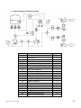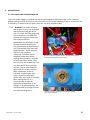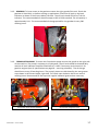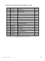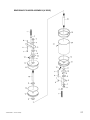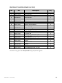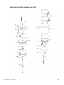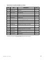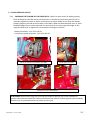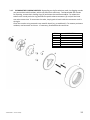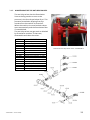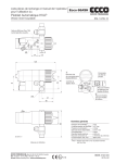
1
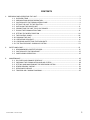
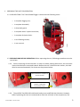
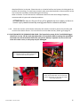
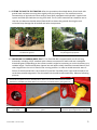
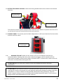
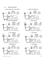
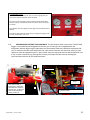
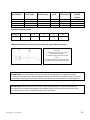
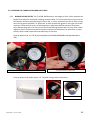
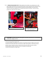
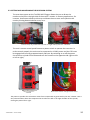
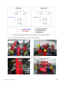
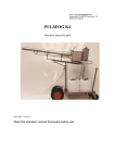
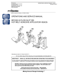
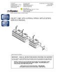
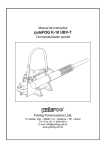
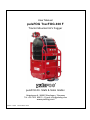
User Manual pulsFOG TracFOG 400 F Tractor Mounted ULV Fogger pulsFOG Dr. Stahl & Sohn GmbH. Abigstrasse 8 / 88662 Überlingen / Germany Tel: +49 7551 92610 – E-mail: [email protected] www.pulsfog.com Version: 1.05/0 Issue: March 2015 CONTENTS 1. PREPARING AND OPERATING THE UNIT ………………………………………………….…………………………………… 3 1.1. SUPPLIED ITEMS …………………………………………………………………………………………………………. 3 1.2. PREPARATIONS BEFORE OPERATION ………………………………………………………………………….. 3 1.3. CUATION WITH THE FORMULATION PUMP ………………………………………………………………… 4 1.4. FITTING THE UNIT TO THE TRACTOR …………………………………………………………………………… 5 1.5. INSTALLING THE DRIVE SHAFT ……………………………………………………………………………………. 6 1.6. CONNECTING THE UNIT TO 12 VDC POWER ……………………………………………………………….. 8 1.7. FILLING THE FORMULATION TANK ……………………………………………………………………………… 8 1.8. SETTING THE NOZZLE POSITION ……………………………………………………………………………….. 10 1.9. THE CONTROL PANEL ……………………………………………………………………………………………….. 10 1.10. RUNNING THE UNIT …………………………………………………………………………………………………. 10 1.11. OPERATING SEQUENCE ……………………………………………………………………………………………. 11 1.12. CHECKING AND SETTING THE FLOW RATE ……………………………………………………………….. 12 1.13. THE TRACFOG 400 F HYDRAULIC SYSTEM ………………………………………………………………… 13 2. SAFETY AND CARE …………………………………………………………………………………………………………………… 15 2.1. RECOMMENDED PROTECTIVE GEAR ……………………………………….………………………………… 15 2.2. CAUTION WITH THE DRIVESHAFT ……………………………………………………………………………... 15 2.3. CARE DURING OPERATION ………………………………………………………………………………………… 15 3. MAINTENANCE ………………………………………………………………………………………………………………………… 16 3.1. OIL CHECK AND CHANGE SCHEDULE …………………………………………………………………………. 16 3.2. CHECKING THE FORMULATION AND AIR FILTERS ………………………………………………………. 18 3.3. SETTING AND MAINTAINING THE REVERSION SYSTEM ……………………………………………… 20 3.4. OTHER PERIODIC CHECKS ………………………………………………………………………………………….. 31 3.5. SERVICING SCHEDULE ……………………………………………………………………………………………….. 34 3.6. TRACFOG 400 F WIRING DIAGRAM …………………………………………………………..…………….... 35 TracFOG 400 F – Version 1.05/0 2 1. PREPARING THE UNIT FOR OPERATION 1.1. SUPPLIED ITEMS. The TracFOG 400F fogger is delivered with following items: o 1 complete fogging unit; o 1 complete driveshaft; o 1 driveshaft guard; o 2 complete lower 3-point-hitch bolts; o 1 complete 3rd point hitch; o 1 set of dosing nozzles; o 1 user manual. 1.2. PREPARATIONS BEFORE OPERATION. Before operating the unit, following procedures must be carried out: 1.2.1. Correct mounting of the hitch bolts. In order to reduce packing dimensions, the two lower 3-point hitch bolts are mounted inwards. Before the unit is hitched to the tractor, the bolts must be mounted outwards, like shown on the pictures below. Bolt mounted for transport, to fit unit into box. Bolt mounted on normal position, ready to be connected to tractor. ‘ 1.2.2. The pulsFOG TracFOG 400 is delivered ready to use and filled with lubricant. However, before operating the unit we recommend to check the oil levels of the components, like TracFOG 400 F – Version 1.05/0 3 described further in the text. Place the unit on a leveled surface and remove its side guards to perform this checking. To avoid injury hazard, make sure the driveshaft is disconnected, so the unit cannot be started by accident during the checking. Refer to Section 3 in this manual for information about oil check and change frequency, recommended oil types and related procedures. ATTENTION! Do not run the unit if any of its guards are not in place, as there is severe injury hazard caused by moving parts such as wheels and belts. 1.2.3. Check the tension of the blower and pump drive belts. Pressed by hand, they should yield no more than about 10 mm. For instructions to set the belt tension, please go to page 13. 1.3. CAUTION WITH THE FORMULATION PUMP. The formulation pump of the TracFOG 400 fogger should not run dry. Fill the tank with about 20 L of formulation before starting the equipment and make sure the formulation ball valve (see picture below) is opened. Do not run the unit when this valve is shut, or the pump may be damaged. Ball valve in the formulation pump feeding line (opened position). Before starting the unit this valve must be opened. For cleaning the formulation filter, shut the valve, unscrew the filter cup and clean the strainer. Remember to open the valve after reassembling the filter. TracFOG 400 F – Version 1.05/0 4 1.4. FITTING THE UNIT TO THE TRACTOR. After the procedures described above, fasten both side guards back into place securing them tightly with the locking nuts. The machine must be connected to an agricultural tractor with at least 50HP, equipped with hydraulic 3-point hitch system and 540 rpm clockwise turning PTO shaft. The 3rd point extension bar should be set so that the unit becomes leveled when lifted 40-50 cm above the ground. Running the unit unleveled may damage the driveshaft and other components. Unit should be leveled when lifted about 40-50 cm above the ground. Incorrect left-right and/or front-end leveling may damage the equipment. 1.5. INSTALLING THE CARDAN DRIVE SHAFT. The TracFOG 400 is supplied with one 50 cm long driveshaft, including 1.3/8” standard quick release connectors on both ends and a complete driveshaft guard. Depending on the tractor model it might be necessary to cut the shaft bars to a suitable length. The driveshaft bars (square bar and square tube) should be inserted about 2/3 of their length when the unit is lifted to the running position. In order to avoid excessive ware or failure of the driveshaft links, the tractors PTO and the TracFOG power input shaft should be set to the best possible alignment. The driveshaft links should be lubricated daily. Observe following pictures: Driveshaft lock (yellow arrow) in locked position. Push in to connect or disconnect driveshaft from PTO or TracFOG input shaft. Make sure connectors are locked before running the unit! TracFOG 400 power input shaft TracFOG 400 F – Version 1.05/0 Complete driveshaft with links, connectors and guard. Correct mounting of the driveshaft. Fix chains to prevent guard from rotating. 5 INSTALLATION SEQUENCE: Place the unit on a leveled surface. Make sure the tractor´s hydraulic hitch levers are wide enough apart to fit the TracFOG. Connect the levers to the left and right hitch bolts on the TracFOG. Do not forget to secure each lever with one of the supplied cotter pins. Lift the unit slightly to facilitate the mounting of the third point rod. Install the 3rd point rod using the supplied 3rd point bolt. Do not forget to secure the assembly with the cotter pin. Lift and level the unit by extending or shortening the 3rd point rod. Be careful not to extend the rod too much, or it may disengage and the unit will drop. Level the unit so the PTO shaft and the input shaft of the TracFOG are on the same height and the horizontal deviation between these shafts is as little as possible. TracFOG 400 F – Version 1.05/0 6 CARDAN SHAFT INSTALLATION: When mounted in place the bars of the cardan shaft should look like on the picture left. If necessary, these bars must be cut to length! Before cutting the shaft, the unit must be lifted and leveled as described on the previous page! In order to measure the bars’ length, disconnect (pull out) the bars and connect the terminals to the PTO and fogger input shaft. Compare, measure and cut to length if necessary. For operation, the plastic protective cover must be in place and in perfect condition! The safety device with M6 fuse screw must me mounted on the fogger side. When mounted in place, the angle between links and bars should not be greater than 10°. Steeper angles may damage the shaft. CAUTION: DO NOT ADJUST THE UNIT´S HEIGHT WHEN THE PTO IS ENGAGED. Links mounted incorrectly Terminals inverted Bars too short Protection cover damaged / missing Bars too long TracFOG 400 F – Version 1.05/0 7 ATENTION! Do not operate the unit if the driveshaft guard is damaged, not properly fastened, incomplete or missing, as there is severe injury hazard. Make sure all links and connectors are integer and properly fixed and the links are not excessively twisted, before starting the unit. Repair or substitute the driveshaft immediately if any damage is noticed. Stay away from the driveshaft and do not allow anyone to remain near it when the unit is running or about to be started. 1.6. CONNECTING THE UNIT TO 12VDC POWER Connect the power cable to a 12VDC automotive battery. Whenever possible, use the own tractor’s battery. Place the control panel in the tractor’s cabin, within the drivers reach. Power cable and control panel 1.7. FILLING THE FORMULATION TANK. Make sure the drain valve is shut and the ball valve in the formulation line is opened. Fill the tank with at least 20 and up to 400 liters of ready and homogenized formulation. The TracFOG 400 features a bypass system that directs part of the formulation flow generated by the pump through an hydraulic agitator back into the tank, providing an agitation effect which helps to avoid decantation. It is recommended, however, to use only perfectly homogeneous and stable formulations, as sediments of solid particles on the bottom of the tank may obstruct the formulation filter, formulation lines, shut-off valves and nozzles. Use the tank intake strainer to filter out larger particles from the formulation. Reinstall the lid after filling the tank. Reinstall the unit’s side guards after checking the ball valves. Formulation line ball valve. Must be opened for operation. TracFOG 400 F – Version 1.05/0 Formulation drain valve. Must be shut before filling the tank. Hydraulic agitator mounted on tank 8 FORMULATION TANK FILLING SEQUENCE Before filling the tank, close the tank drain valve and open the pump feed line valve! The tank takes up to 400 Liters (100 gal). For water based solutions and suspensions: 1. Fill the tank with at least 80% of the required amount of water, which should be not less than 30 Liters (8 gal). 2. Mix the chemical into a slurry in a separate container. 3. Start PTO and rev up to 540 rpm max. 4. Pour slurry slowly into the tank. 5. If necessary, complete the required volume with water. For oil based emulsions: 1. 2. 3. 4. 5. 6. Fill the tank with at least 30 Liters (8 gal) of water. Start PTO and rev up to 540 rpm max. Slowly pour the entire volume of emusifiable oil into the tank. Mix the chemical into a slurry in a separate container. Pour slurry into the tank. Complete the required volume with water. WARNINGS TracFOG 400 F – Version 1.05/0 Never pour powders, granulates or any other solid formulations directly into the empty tank, which will damage the formulation lines, filters and formulation pump! Drain possible formulation remains from the tank immediately after the application. Rinse the tank with clear water immediately afterwards. Start the unit and make the clear water flow through the pump and formulation lines. Clean the formulation filters after every application! Do not allow the pump to run dry! If the fogging starts failing (formulation level is too low and pump is sucking air), fill in more formulation before continuing the application. Use the supplied strainer to avoid dirt from getting into the tank! Replace the lid after filling the tank to avoid spilling formulation! 9 1.8. SETTING THE NOZZLE POSITION. Loosen the locking handles and set the nozzles to the desired direction. Set stroke distance using limiter bolts. Loosen handles to set nozzle position. The reversion system requires compressed air from the unit’s blower to operate. Run the unit to try and set the reversion stroke distance and nozzle position. 1.9. CONTROL PANEL. The control panel includes independent on-off control switches for the nozzles and the reversion switch. The TracFOG 400 F control panel 1.10. RUNNING THE UNIT. Make sure the tractor’s PTO is set to 540 rpm clockwise (or counterclockwise if looking from the tractor towards the fogger), which complies with the international standard. Some tractors feature reversible PTO’s. In those cases, make sure to set the tractor correctly before starting the PTO. ATTENTION! Never run the PTO in reverse, which may damage the blower and other components. ATTENTION! Do not exceed the tractor’s standard operation speed (540 rpm at the PTO) while running the TracFOG. Running the unit with excessive speed may damage the blower and other components. In order to obtain the best possible performance during operation, keep the tractor’s engine running as close as possible to the standard operation speed. The air pressure gauge will then indicate between 0.6 and 0.7 kgf/cm2. TracFOG 400 F – Version 1.05/0 10 1.11. OPERATING SEQUENCE 1 – START ENGINE (IDLE) / CHECK HEIGHT 3 – REV UP (540 RPM MAX!) 2 – SMOOTHLY ENGAGE PTO 4 – START FOGGING 5 – STOP FOGGING 6 – REV DOWN 7 – DISENGAGE PTO 8 – STOP ENGINE TracFOG 400 F – Version 1.05/0 11 TracFOG 400 F panel. At 540 rpm on the intake shaft, the air pressure gauge (on the left) should indicate between 0,4 and 0,6 bar. The spray pressure gauge (center) should indicate about 80 psi when the spray is turned off and at least 35 psi when the spray is turned on. The agitation pressure gauge (on the right) should indicate about 350 psi. In order to extend the life of the spray and agitation gauges keep the taps closed when not in use. 1.12. CHECKING AND SETTING THE FLOW RATE. The formulation flow rate on the TracFOG 400 fogger is controlled by exchangeable restriction jets. A basic jet set is supplied with the equipment. Before beginning an application the formulation flow rate should be measured and set. To measure the flow rate disconnect the nylon tubes from the two anti-drip valves (1) and replace it with the supplied nylon ¼” spare tubes. Start the unit and retrieve the formulation into a cup or other container (e.g. during one minute). Calculate the flow rate by dividing the retrieved liquid volume by the measured time. 2 Safety valve Formulation pump Disconnect this tube (1) and replace it with a spare tube to collect the formulationand measure the flow rate. To alter the flow rate exchange the dosing nozzle (2). TracFOG 400 F – Version 1.05/0 1 Partial view of the TracFOG 400 F hydraulic system. 12 Dosing nozzle (line intake) # Dosing nozzle (line exit) # Spray-off pressure (psi) Nozzle jet # Spray-on pressure (psi) 13 13 13 13 20 20 20 20 78 78 78 78 7 8 9 10 41 39 36 33 Flow rate (two nozzles) ml/min 720 764 814 870 Standard supplied nozzles: Nozzle # Qty. 7 2 8 2 10 2 13 1 20 1 IMPORTANT NOTICE: releasing the tube from the quick release connector. To release the nylon tube from the connector: 1 – With one hand push the ring (1) towards the connector. 2 – With the other hand pull out the tube. To reassemble the set simply push the tube into the connector until it sits tight. ATTENTION! The return valve must remain open during operation. It might be closed for maintenance purpose only. After finishing servicing, the unit the return valve must be opened immediately. Running the unit with closed return valve may cause accidents and damage the unit. ATTENTION! The outlet valve must not be closed during operation, which will impede the formulation flow and may damage the formulation pump. Close this valve only to clean the formulation filter strainer. Open the outlet valve afterwards. TracFOG 400 F – Version 1.05/0 13 1.13. TRACFOG 400 F HYDRAULIC SYSTEM Item 1 2 3 4 5 6 7 8 9 10 12 13 14 15 17 18 19 20 21 22 23 TracFOG 400 F – Version 1.05/0 Description Formulation tank Drain valve Return valve Outlet valve Inline filter Formulation pump Spray line valve Safety valve (400 psi) Dosing nozzle (line intake) T conector for ¼” plastic tube T conector 2F x 1M ¼” NPT Dosing nozzle (line exit) Spray pressure gauge Agitator (eductor) Solenoid valve Spray nozzle shut off valve Anti drip valve Dosing nozzle for spray nozzle Dosing nozzle seat 11/16” Dosing nozzle seat 9/16” Agitation pressure gauge Quant. 1 1 1 1 1 1 1 1 1 3 1 1 1 1 2 2 2 2 2 2 1 14 2. SAFETY AND CARE 2.1. RECOMMENDED PROTECTIVE GEAR. Always use all recommended personal protective equipment during preparation of the formulation, application and cleaning or washing the equipment. The tractor driver should wear a full-face respirator with filter-class compatible with the applied formulation. Tractors with enclosed cabs should be preferred. 2.2. CAUTION WITH THE DRIVESHAFT. Follow all local regulations and safety guidelines regarding PTO drive shafts. Do not use the driveshaft without its guard. Use chains to fix both ends of the guard respectively to the tractor and to the fogger. Stop the application immediately if any malfunction or damage is noticed on the driveshaft or its guard. Before starting the operation, make sure the driveshaft is properly mounted as described in this manual, and that its connectors are firmly seated and locked. 2.3. CARE DURING OPERATION. 2.3.1. Before starting the unit, make sure all guards are properly mounted and locked. 2.3.2. Do not exceed the standard speed of 540 rpm at the PTO. Excessive speed may damage the unit. 2.3.3. Check the oil levels on gearbox, blower and spray pump daily. Follow the oil change schedule shown ahead on section 3.4. Check air and formulation filters regularly, as well as spray pump and blower drive belts tension and wear. 2.3.4. The TracFOG 400 should only be operated by professional and properly trained personnel. ATTENTION! Never perform any servicing on the unit while it is running. ATTENTION! Do not remove the unit’s protective guards while it is running. Do not start the unit while its protective guards are not properly mounted and locked. Disconnect the driveshaft from the PTO before removing any of the unit’s guards. TracFOG 400 F – Version 1.05/0 15 3. MAINTENANCE 3.1. OIL CHECK AND CHANGE SCHEDULE The TracFOG 400 fogger is supplied with all oil pans adequately filled and ready to use. However, before starting the unit for the first time, check the oil level at the following 4 points, and fill with oil if necessary. To perform the oil check, place the unit on a leveled surface. 3.1.1. BLOWER: the blower features two oil pans, one on the driveshaft side and one on the gear drive side. To access the filling plugs and level indicator on the shaft side, remove the left guard of the unit. The recommended oil specification for the blower is ISO VG-220 standard compliant oil. The approximate oil capacities are 0.25 L (driveshaft side) and 0.40 L (opposite side). These volumes, however, are only basic references. The level control should be made daily before starting the application, using the oil level indicators shown in the pictures, with the leveled unit. The unit must be off for at least five minutes. The oil level should fill about half to ¾ of the indicator. Milky appearance of the oil indicates contamination with water. Should the milkyness persist after more than 15 minutes after starting the unit, it is recommended to stop the application and perform an oil change. In normal conditions, the recommended oil change period is every 500 working hours. TracFOG 400 F – Version 1.05/0 Oil level indicators (yellow arrows), oil drain tubes (white arrows) and oil fill lids (green arrows). Oil level indicator showing correct oil level (filling half of the indicator). 16 3.1.2. GEARBOX. To have access to the gearbox remove the right guard of the unit. Check the gearbox oil level daily, or before starting an application. Check the oil level on the level indicator as shown in the Picture below, left side. The oil level should fill half to ¾ of the indicator. The recommended oil should comply to ISO VG-220 standard. The oil capacity is approximately 0.4 L. The recommended oil change period for the gearbox is every 500 working hours. Gearbox with level indicator and refill plug. 3.1.3. FORMULATION PUMP: To access the formulation pump remove the guard on the right side of the machine. The pump’s crankcase is oil lubricated. The oil level should be checked daily and the oil level indicator should be filled half to ¾. Refill if necessary with mineral oil for gasoline engines (see oil specifications on page 18 – servicing schedule) . The oil change should occur every 50 working hours. The pump’s pistons are lubricated by the two greaser cups shown in the Picture below, right side. Turn both cups clockwise half a turn each 8 working hours. Remove and fill the cups with regular industrial grease when necessary. Formulation pump oil level indicator TracFOG 400 F – Version 1.05/0 Oil refill cap and greaser cups 17 3.2. CHECKING THE FORMULATION AND AIR FILTERS 3.2.1. BLOWER INTAKE FILTER. The TracFOG 400 features a two-stage air filter, which protects the blower from particles and liquid, avoiding excessive wear. To ensure that the unit runs with its full capacity, without compromising its service life, it is very important that the air filter is kept clean and in good conditions. To access the air filter remove the guard on the right side of the machine. Check the filter every 50 working hours. Substitute the filter element #1 at least every 200 working hours. Do not run the unit if the filtering element #1 is missing. Also, check regularly the air suction hose (which connects the filter to the blower) for punctures or loose clamps, which could compromise the efficiency of the filter. Filtering element #1: ref. TR 1510 (compatible Ford F1000/2000/4000 and Mercedes Benz 709) To open filter release butterfly nut. To remove element release nut. Filtering element #2 (safety filter): ref. TR 1910. Change when visibly dirty Air deflector TracFOG 400 F – Version 1.05/0 18 3.2.2. FORMULATION INLINE FILTER. The formulation inline filter is very important, as it will retain large solid particles that may find their way into the formulation tank, protecting the formulation pump. This filter should be checked and cleaned daily, which will avoid unplanned stops during application caused by obstruction of the filter. Access the filter through the right side of the machine. Filter cup and strainer. Before opening the filter, shut the formulation line ball valve (shown here in open position). ATTENTION! To perform the filter cleaning wear the same protective gear recommended for preparing the fogging solution. 1. Shut the formulation line ball valve. 2. Unscrew the filter cup and pour its content into a proper container or back into the tank. 3. Remove the strainer from the cup and rinse it under running water. If necessary remove residues using a smooth brush (e.g. tooth brush). Rinse the cup to eliminate residues. 4. Reassemble and fasten the filter cup. Do not forget the sealing ring. 5. Open the formulation line ball valve. TracFOG 400 F – Version 1.05/0 19 3.3. SETTING AND MAINTAINING THE REVERSION SYSTEM The reversion system on the TracFOG 400 F fogger allows the user to direct the nozzles to the left or the right side of the tractor´s motion. In forestry applications, for instance, that feature allows to drive up and down the tree rows and reposition the nozzles pointing downwind after every turn. Nozzles may be pointed to left side or right side of tractor´s motion. The unit´s remote control panel features a power switch to operate the reversion. In order to work properly the unit must be connected to 12 VDC power and the PTO must be engaged and running at approximately 540 rpm. By switching on or off the power the reversion cylinder will actuate and turn the nozzles to the opposite side (right to left or left to right). Reversion power switch Reversion valves and pressure tubes The power to produce the movement comes from compressed air generated by the unit´s blower. Two 3way solenoid valves direct the compressed air to either the left or the right chamber of the cylinder, moving the piston left or right. TracFOG 400 F – Version 1.05/0 20 Reversion cylinder, pressure lines, valves, and their action to reverse nozzles. Set nozzle angles by hand loosening the handles like shown below. The cylinder´s stroke can be set with the limiter screws shown below. TracFOG 400 F – Version 1.05/0 21 The steel cable, which transmits the pistons movement to the nozzles, must be slightly tensioned and fixed to the nozzles barrel. When the unit is not running, it should be possible to move the nozzles along with the piston from one side to the other by hand. These barrels must be lubricated with Molykote PG-75 grease. A small gap of 2 mm (arrows) between each barrel and the pole allows the barrels to rotate freely. The barrels are linked together from the inside in order to turn simultaneously when the reversion is switched on or off. To ensure the mechanism to work properly, the cylinder must be properly fixed to the pole through the two clamps. The blue air tubes must be properly connected according to the diagram shown on page 2. Do not switch air and formulation tubes! TracFOG 400 F – Version 1.05/0 22 FOGGING POLE, BARRELS AND NOZZLES ASSEMBLY (V. 2013) TracFOG 400 F – Version 1.05/0 23 FOGGING POLE, BARRELS AND NOZZLES ASSEMBLY (V.2013) Pos 1 2 3 4 5 6 7 8 9 10 11 12 13 14 16 17 18 19 20 21 22 23 24 25 Ref S00092.00 C00248.00 N00195.00 N00176.00 A00465.00 N00108.00 S00092.00 N00033.00 N00072.00 M00041.00 C00659.00 A00466.00 N00133.00 S00092.00 C00141.00 C00538.00 S00108.00 A00149.00 C00685.00 C00686.00 A00467.00 M00041.00 M00041.00 Description Fogging pole Formulation tube connectors M10 x 80 screw M10 washer M10 rubber washer M10 self-clinching nut Crosspiece M10 spring washer M10 nut M10 bolt 110 mm Sealing ring 53,57 x 3,53 mm Rotating barrel front side M5 set Nozzle holding elbow M10 handle Elbow connecting set 1/4” x 1/8” NPT male quick connector Nozzle assembly Locking ring 1/8” steel cable Cable clamp Rotating barrel rear side M10 bolt 105 mm M10 bolt 125 mm Qty 1 2 2 10 4 2 2 4 4 1 2 1 3 2 2 2 2 2 2 1 4 1 1 1 Lubricate moving parts with Molykote PG-75 high temperature grease. TracFOG 400 F – Version 1.05/0 24 FOGGING POLE, BARRELS AND NOZZLES ASSEMBLY (V. 2015) TracFOG 400 F – Version 1.05/0 25 FOGGING POLE, BARRELS AND NOZZLES ASSEMBLY (V. 2015) Pos 1/21 2 3 4 5 6 7 8 9 10 12 13 14 15 16 17 18 19 20 22 23 Ref S00092.01 C00248.00 N00195.00 N00176.00 A00465.00 N00108.00 S00092.01 C00659.00 A00466.01 N00133.00 S00092.01 S00108.00 A00149.00 C00685.00 C00686.00 A00467.01 N00033.00 M00041.00 C00782.00 C00721.00 Description Fogging pole Formulation tube connectors M10 x 80 screw M10 washer M10 rubber washer M10 self-clinching nut T-piece Sealing ring 53,57 x 3,53 mm Rotating barrel front side M5 set Nozzle holding elbow Elbow connecting set Nozzle assembly Locking ring 1/8” steel cable Cable clamp Rotating barrel rear side M10 spring washer M10 bolt 125 mm Clamp Sealing ring 78,97 x 3,53 mm Qty 1 2 2 6 4 2 2 2 1 3 2 2 2 2 1 4 1 2 1 1 1 Lubricate moving parts with Molykote PG-75 high temperature grease. TracFOG 400 F – Version 1.05/0 26 REVERSING CYLINDER ASSEMBLY (V.2013) TracFOG 400 F – Version 1.05/0 27 REVERSING CYLINDER ASSEMBLY (V.2013) Pos 1 2 3 4 5 6 7 8 9 10 11 12 13 14 15 16 17 18 19 20 21 Ref N00152.00 N00176.00 N00048.00 N00046.00 A00468.00 N00145.00 A00469.00 A00470.00 N00159.00 A00471.00 C00706.00 C00503.00 A00472.00 C00714.00 A00473.00 C00715.00 A00474.00 A00475.00 C00121.00 A00476.00 N00078.00 Description M10 X 70 screw M10 washer M14 self-clinching nut M14 washer U shaped piece M6 nut Eyebolt M6 Special M14 washer Self-tapping screw 15 mm Seal cover ring Sealing ring 21,82 x 3,53 mm 1/4” x 1/8” quick elbow connector Cylinder lid Sealing ring 101,32 x 5,33 mm M14 bolt #1 Sealing ring 113,67 x 5,33 mm Piston M14 bolt #2 Clamp Cylinder Self-tapping screw 25 mm Qty 2 2 2 2 2 4 2 4 6 2 2 4 2 2 1 1 1 1 2 1 6 Lubricate moving parts with Molykote PG-75 high temperature grease. TracFOG 400 F – Version 1.05/0 28 REVERSING CYLINDER ASSEMBLY (V.2015) TracFOG 400 F – Version 1.05/0 29 REVERSING CYLINDER ASSEMBLY (V.2015) Pos 1 2 2A 3 4 5 6 7 8 9 10 11 12 13, 14, 17 15 16 18 19 20 21 Ref N00152.00 N00072.00 N00108.00 N00176.00 A00468.01 A00471.00 N00145.00 A00469.00 N00159.00 C00657.00 C00503.00 A00472.01 C00660.00 A00474.01 Description M10 X 70 screw M10 nut M10 self-clinching nut M10 washer U shaped piece Seal cover ring M6 nut Eyebolt M6 Self-tapping screw 15 mm Sealing ring 15,47 x 3,53 mm 1/4” x 1/8” quick elbow connector Cylinder lid Sealing ring 113,89 x 3,53 mm M10 bolt assembly A00474.01 C00715.00 C00782.00 A00476.01 N00078.00 N00078.00 Piston Sealing ring 113,67 x 5,33 mm Clamp Cylinder Self-tapping screw 25 mm M4 washer Qty 2 2 2 6 2 2 4 2 6 3 4 2 2 1 1 1 2 1 6 6 Lubricate moving parts with Molykote PG-75 high temperature grease. TracFOG 400 F – Version 1.05/0 30 3.4. OTHER PERIODIC CHECKS. 3.4.1. CHECKING THE TENSION OF THE DRIVE BELTS. (weekly or after every 50 working hours). Push each belt by hand like shown on the picture. It should not yield more than 10 mm. If necessary tighten the belts as shown on the pictures below. Make sure to keep the wheels properly aligned, to avoid excessive wear of the belts. When the belts become worn or show shredded edges they must be replaced. Use only belts of the same type and length as the originals. Make sure to tighten all screws before starting the machine. Blower drive belts: 2 x A-52 or HA-52 Formulation pump drive belt: 1 x A-36 or HA-36 Check the tension of the blower drive belts. Checking the pump belt. Fixing screws and screw tensioner. ATTENTION! Before performing any servicing that requires opening any of the equipment’s guards, make sure the driveshaft is disconnected from the tractor, as moving parts such as wheels and belts are very hazardous and may cause severe injury.`` TracFOG 400 F – Version 1.05/0 31 3.4.2. CLEANING THE FOGGING NOZZLES. Depending on the formulation used, the fogging nozzles may accumulate solid residues, which will affect their efficiency. To disassemble the nozzles for cleaning, remove their locking rings (9) and draw the nozzle assemblies. To release the tube from a nozzle push the ring towards the quick-release connector (1) and pull the hose out at the same time. To reconnect the tube, simply push it back inside the connector until it sits tight. Clean the nozzles using a smooth non-metallic brush (e.g. a toothbrush). To remove persistent residues, use kerosene or thinner. If necessary, disassemble the nozzle set. ITEM 1 2 3 4 5 6 7 1 2 3 DESCRIPTION Push-in quick release connector Nozzle central piece Deflector Spacers Restriction plate 18,9 mm M3 x 25 screws Locking ring 4 5 6 TracFOG 400 F – Version 1.05/0 7 32 3.4.3. MAINTENANCE OF THE ANTI-DRIP VALVES. The anti-drip valves shut the formulation lines to the fog nozzles as soon as the pressure in the lines drops below 15 psi. This prevents formulation dripping from the nozzles after the machine is turned off. When the machine is turned on both valves open automatically and the formulation flow is reestablished. The anti-drip valves may get stuck or blocked by formulation residues. In that case, disassemble and clean the valves. ITEM DESCRIPTION VG-201 VG-202 VG-203A VG-204 VG-207 VG-208 VG-209A VG-209B VG-209C VG-210 VG-211 VG-212 VG-213 VG-214 VG-215A VG-216 Restriction jet Gasket FI 12/8/1 Dosing nozzle seat 9/16” M14 washer 1/4” ball valve 1/4” x 1/8” NPT male adaptor Quick male T ¼ x ¼ NPT Male elbow ¼ x ¼ NPT Barbed male conector ¼ x ¼ NPT Anti-drip valve Filter Gasket / O-ring Restriction plate Gasket Female adapter Nozzle quick release cap TracFOG 400 F – Version 1.05/0 One of two anti-drip valves on the TracFOG 400 F 33 3.5. SERVICING SCHEDULE PERIOD DAILY Every 50 working hours Every 200 working hours Every 500 working hours EVENT DIRECTIONS Check oil level on blower on both sides (shaft and gear drive side). If necessary, complete level using ISO VG-220 oil. Check oil level on gear box. If necessary, complete level using ISO VG-220 oil. Check oil level on formulation pump. If necessary, complete level using mineral oil for gasoline engines.(1) Clean formulation filter. - Grease formulation pump pistons. If necessary refill with regular mineral grease. Formulation pump oil change Use mineral oil for gasoline engines.(1) Check the blower intake filter TR 1510 filter element Check tension of blower drive belts. A-44 or HA-44 belts Check tension of formulation pump drive belt. A-38 ou HA-38 belt Change blower intake filter element. TR 1510 filter element Blower oil change (both oil pans). ISO VG-220 oil Gearbox oil change. ISO VG-220 oil (1) – Acceptable oil specifications for the formulation pump: SAE 10W40 / SAE 5W40 / SAE 10W30 / SAE 5W30 TracFOG 400 F – Version 1.05/0 34 3.6. TRACFOG 400 F WIRING DIAGRAM TracFOG 400 F – Version 1.05/0 35