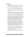
1
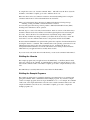
aDIO Driver for Linux
User’s Manual
Version 1.3
SWM-640000019
rev A
RTD Embedded Technologies, INC.
103 Innovation Blvd.
State College, PA 16803-0906
Phone: +1-814-234-8087
FAX: +1-814-234-5218
E-mail
[email protected]
[email protected]
web site
http://www.rtd.com
aDIO Driver for Linux
ii
Revision History
07/30/2004
Revision A issued
Documented for ISO9000
aDIO Driver for Linux
Published by:
RTD Embedded Technologies, Inc.
103 Innovation Blvd.
State College, PA 16803-0906
Copyright 2004 by RTD Embedded Technologies, Inc.
All rights reserved
Printed in U.S.A.
The RTD Logo is a registered trademark of RTD Embedded Technologies. cpuModule and aDIO
are trademarks of RTD Embedded Technologies. PC/104 is a registered trademark of PC/104
Consortium. All other trademarks appearing in this document are the property of their respective
owners.
iii
aDIO Driver for Linux
Table of Contents
TABLE OF CONTENTS ..............................................................................................................4
INTRODUCTION .........................................................................................................................5
INSTALLATION INSTRUCTIONS............................................................................................6
EXTRACTING THE SOFTWARE .......................................................................................................6
CONTENTS OF INSTALLATION DIRECTORY ....................................................................................6
BUILDING THE DRIVER .................................................................................................................6
BUILDING THE LIBRARIES .............................................................................................................7
BUILDING THE EXAMPLE PROGRAMS ...........................................................................................7
USING THE API FUNCTIONS...................................................................................................8
FUNCTION REFERENCE ..........................................................................................................9
API FUNCTION GROUPS ........................................................................................................10
GENERAL....................................................................................................................................10
INTERRUPT CONTROL AND STATUS ............................................................................................10
DIGITAL INPUT/OUTPUT PORT ACCESS AND CONTROL ...............................................................10
ALPHABETICAL FUNCTION LISTING................................................................................11
EXAMPLE PROGRAMS REFERENCE..................................................................................26
LIMITED WARRANTY.............................................................................................................27
aDIO Driver for Linux
iv
Introduction
This document targets anyone wishing to write Linux applications for an RTD cpuModule with
aDIO capability. It provides information on building the software and about the Application
Programming Interface used to communicate with the hardware and driver. Each high-level
library function is described as well as any low-level ioctl() system call interface it may make use
of.
The diagram below 1) provides a general overview of what hardware and software entities are
involved in device access, 2) shows which units communicate with each other, and 3) illustrates
the methods used to transfer data and control information.
Application
Application
Application
C Function Calls
C Function Calls
C Function Calls
Library
ioctl() System Calls
User Space
Kernel Space
Driver
Software
Memory Accesses
Hardware
Bus
Electrical Signals
Hardware
5
aDIO Driver for Linux
Installation Instructions
Extracting the Software
All software comes packaged in a gzip’d tar file named aDIO_Linux_v1.3.tar.gz. First, decide
where you would like to place the software and make a copy of the tar file in this directory by
issuing the command “cp <path to tar file>/aDIO_Linux_v1.3.tar.gz <installation path>”
substituting the appropriate paths for <path to tar file> and <installation path>. Next, change your
current directory to where you made a copy of the tar file by issuing the command
“cd <installation path>”. Once you are in this directory, extract the software by issuing the
command “tar –xvzf aDIO_Linux_v1.3.tar.gz”; this will create a directory
aDIO_Linux_v1.3/ which contains all the files that are part of the software package.
Contents of Installation Directory
Once the tar file is extracted, you should see the following files and directories within
aDIO_Linux_v1.3/:
driver/
examples/
include/
lib/
CHANGES.TXT
LICENSE.TXT
README.TXT
The file CHANGES.TXT describes the changes made to the software for this release, as well as
for previous releases. The file LICENSE.TXT provides details about the RTD end user license
agreement which must be agreed to and accepted before using this software. The file
README.TXT contains a general overview of the software and contact information should you
experience problems, have questions, or need information. The directory driver/ contains the
source code and Makefile for the drivers. The directory examples/ holds the source code and
Makefile for the example programs. The directory include/ contains all header files used by the
driver, example programs, library, and your application programs. Library source code and
Makefile reside in the directory lib/.
Building the Driver
Driver source code uses files located in the kernel source tree. Therefore, you must have the full
kernel source tree available in order to build the driver. The kernel source tree consumes a lot of
disk space, on the order of 100 to 200 megabytes. Because production systems rarely contain this
much disk space, you will probably use a development machine to compile the driver source code.
The development system, which provides a full compilation environment, must be running the
exact same version of the kernel as your production machine(s); otherwise the kernel module may
not load or may load improperly. After the code is built, you can then move the resulting object
files, libraries, and executables to the production system(s).
Building the driver consists of several steps: 1) compiling the source code, 2) loading the
resulting kernel module into the kernel, and 3) creating hardware device files in the /dev
directory. To perform any of the above steps, you must change your current directory to driver/.
The file Makefile contains rules to assist you.
aDIO Driver for Linux
6
To compile the source code, issue the command “make”. This will create the driver object file
rtd-aDIO.o. The GNU C compiler gcc is used to build the driver code.
Before the driver can be used, it must be loaded into the currently running kernel. Using the
command “make insmod” will load the aDIO driver into the kernel.
When you load the kernel driver, the insmod command will print the following message:
"Warning: loading ./rtd-aDIO.o will taint the kernel: no license"
You can safely ignore this message since it pertains to GNU General Public License (GPL)
licensing issues rather than to driver operation.
The final step is to create a /dev entry for the hardware. Previous versions of the driver always
assumed a character device major number of 122 when registering the device and creating the
/dev entry. Instead, the driver now asks the kernel to dynamically assign a major number.
Since this major number may change each time you load the driver, the best way to create the
device file is to use the command "make devices"; this generates the file /dev/rtd-aDIO.
Be aware that driver/Makefile sets up the include path for the compiler to find kernel header files
by using the "uname -r" command. This command retrieves the operating system release for the
running kernel; the release is the same as the kernel version. Compiling the driver on a
development machine which does not run the same kernel version as the production machine
which will host your application almost certainly invites trouble.
If you ever need to unload the driver from the kernel, you can use the command "make rmmod".
Building the Libraries
The example programs and your application use the aDIO library, so the library must be built
before any of these can be compiled. To build the library, change your current directory to lib/
and issue the command “make”. The GNU C compiler gcc is used to compile the library source
code.
The aDIO library is statically linked and is created in the file librtd-aDIO.a.
Building the Example Programs
The example programs may be compiled by changing your current directory to examples/ and
giving the command “make”, which builds all the example programs. If you wish to compile
a subset of example programs, there are targets in Makefile to do so. For example, the command
“make event” will compile and link the source file event.c and the command "make strobe" will
compile and link the source file strobe.c. The GNU C compiler gcc is used to compile the
example program code.
7
aDIO Driver for Linux
Using the API Functions
aDIO hardware and the associated driver functionality can be accessed through the library API
(Application Programming Interface) functions. Applications wishing to use aDIO library
functions must include the include/aDIO_library.h header file and be statically linked with the
lib/librtd-aDIO.a library archive.
Because of changes made in this version of the driver, existing source code which uses library
functions will not compile and may experience run-time problems. There are four areas which
will require attention on your part:
* Some header files have been renamed. Users upgrading from a previous driver version will
need to modify source code to include the appropriate header files.
* All header files have been relocated to include/. Be sure to update any files which contain
hardcoded header file paths.
* The aDIO /dev entry file name has changed. The device file /dev/adio is now
/dev/rtd-aDIO.
* Some functions have been made private, that is they are no longer accessible to
applications. These routines are ClearIrq_aDio(), InPort(), OutPort(), and signal_handler().
If you are upgrading from a previous driver version and your application uses these
functions, you will either need to rewrite source code to call another library function, make
the appropriate ioctl() call, or modify the library so that these private functions are visible
again.
The following function reference provides for each library routine a prototype, description,
explanation of parameters, and return value or error code. By looking at a function’s entry, you
should gain an idea of: 1) why it would be used, 2) what it does, 3) what information is passed
into it, 4) what information it passes back, 5) how to interpret error conditions that may arise, and
6) the ioctl() system call interface if the function makes use of a single ioctl() call.
Note that errno codes other than the ones indicated in the following pages may be set by the
library functions. Unless otherwise noted in the description of a function'
s return value, please
see the ioctl(2) man page for more information.
aDIO Driver for Linux
8
Function Reference
9
aDIO Driver for Linux
API Function Groups
General
ClearDio_aDio
close_aDio
OpenDIO_aDio
ReadControlRegister_aDio
Interrupt Control and Status
EnableInterrupts_aDio
GetInterruptMode_aDio
InstallISR_aDio
RemoveISR_aDio
Digital Input/Output Port Access and Control
LoadComp_aDio
LoadMask_aDio
LoadPort0BitDir_aDio
LoadPort1PortDir_aDio
ReadComp_aDio
ReadPort_aDio
ReadStrobe0_aDio
ReadStrobe1_aDio
WritePort_aDio
aDIO Driver for Linux
10
Alphabetical Function Listing
ClearDio_aDio
int ClearDio_aDio(void);
Description:
Clear the aDIO circuitry. This performs the following actions: 1) sets all aDIO Compare Register
bits to zero, 2) sets all aDIO Mask Register bits to zero, 3) sets all aDIO Control Register bits to
zero, 4) sets all aDIO Port 0 Data Register bits to zero, and 5) sets all aDIO Port 1 Data Register
bits to zero.
Parameters:
None.
Return Value:
0:
Success.
-1:
Failure. Please see the descriptions of the internal functions InPort() and
OutPort() for information on possible values errno may have in this case.
IOCTL Interface:
This function makes use of several ioctl() requests.
close_aDio
int close_aDio(void);
Description:
Close the device file associated with the aDIO device.
Parameters:
None.
Return Value:
0:
Success.
-1:
Failure. Please see the fclose(3) man page for information on possible
values errno may have in this case.
IOCTL Interface:
None.
11
aDIO Driver for Linux
EnableInterrupts_aDio
int EnableInterrupts_aDio(uchar Mode);
Description:
Enable or disable aDIO digital interrupts. If interrupts are enabled, this also will set the interrupt
mode.
NOTE:
Before enabling interrupts, an interrupt callback function should be installed via
InstallISR_aDio().
NOTE:
Whenever any interrupt mode is enabled, this function will set the direction for all
Port 0 bits to input.
NOTE:
After match mode is enabled, you should load the desired bit mask into the Compare
Register with LoadComp_aDio().
Parameters:
Mode:
Interrupt mode selector. Valid values are:
DISABLE_INT_MODE (0) Disable digital interrupts
EVENT_INT_MODE (1)
Enable event mode interrupts
STROBE_INT_MODE (2)
Enable strobe mode interrupts
MATCH_INT_MODE (3)
Enable match mode interrupts
Return Value:
0:
Success.
-1:
Failure with errno set as follows:
EINVAL
Mode is not valid.
Please see the descriptions of the internal functions ClearIrq_aDIO(),
InPort(), and OutPort() and the description of LoadPort0BitDir_aDio() for
information on other possible values errno may have in this case.
IOCTL Interface:
This function makes use of several ioctl() requests.
GetInterruptMode_aDio
int GetInterruptMode_aDio(uchar *mode);
Description:
Return the current aDIO digital interrupt mode.
aDIO Driver for Linux
12
Parameters:
mode:
Address where interrupt mode will be stored. DISABLE_INT_MODE (0)
will be stored here if digital interrupts are disabled. EVENT_INT_MODE
(1) will be stored here if digital interrupts are in event mode.
STROBE_INT_MODE (2) will be stored here if digital interrupts are in
strobe mode. MATCH_INT_MODE (3) will be stored here if digital
interrupts are in match mode. Nothing is written to this memory location if
the function fails.
Return Value:
0:
Success.
-1:
Failure. Please see the description of the internal function InPort() for
information on possible values errno may have in this case.
IOCTL Interface:
struct DEVICE_IO_Data ioctl_request;
int descriptor;
int status;
/*
* Before calling ioctl(), descriptor must be set up. This is not shown here.
*/
/*
* Read from aDIO Control Register at base I/O address + 0x3
*/
ioctl_request.Port = rCONTROL;
/*
* Any value works here because it is ignored making this request. However, on return from
* ioctl(), the member variable Data contains the register contents.
*/
ioctl_request.Data = 0;
status = ioctl(descriptor, ADIO_IOCTL_INB, &ioctl_request);
if (status == 0) {
/*
* Mask off all Control Register bits except 3 and 4, then shift them so they are now the least
* significant bits
*/
switch ((ioctl_request.Data & 0x18) >> 3) {
case 0:
fprintf(stdout, "Digital interrupts disabled.\n");
break;
13
aDIO Driver for Linux
case 1:
fprintf(stdout, "Digital interrupts in strobe mode.\n");
break;
case 2:
fprintf(stdout, "Digital interrupts in event mode.\n");
break;
}
}
case 3:
fprintf(stdout, "Digital interrupts in match mode.\n");
break;
InstallISR_aDio
int InstallISR_aDio(void (*IsrIrq)(void));
Description:
Install a function which will be called whenever a digital interrupt occurs and the driver sends a
signal to the process to indicate that the interrupt happened.
NOTE:
Signal SIGUSR2 is used to provide notification. Whenever an interrupt occurs, the
kernel sends SIGUSR2 to any process which wanted to know when such an interrupt
occurs. Therefore, your application cannot use SIGUSR2 for some other purpose if
it wishes to be notified of interrupts. Also, whatever SIGUSR2 disposition that was
set prior to calling this function will be overwritten and setting a SIGUSR2
disposition after calling this function will nullify interrupt notification.
Parameters:
IsrIrq:
The function to be invoked when the interrupt occurs.
Return Value:
0:
Success.
-1:
Failure with errno set as follows:
EFAULT
Address of third ioctl() argument is not valid.
EINVAL
IsrIrq is NULL.
EINVAL
Driver has invalid pointer to aDIO device structure.
EINVAL
ioctl() request code is not valid.
EINVAL
aDIO IRQ is disabled in the BIOS.
EINVAL
multiPort is disabled in the BIOS or is set to parallel or floppy
port; applicable only on VIA Eden processor.
aDIO Driver for Linux
14
EINVAL
The Signo member of the ADIO_CallBack structure passed to
ioctl() does not represent a valid signal number.
Please see the sigaction(2) man page, the sigprocmask(2) man page, the
ioctl(2) man page, and the description of RemoveISR_aDio() for
information on other possible values errno may have in this case.
IOCTL Interface:
None.
LoadComp_aDio
int LoadComp_aDio(uchar Value);
Description:
Write an 8-bit value into the aDIO Compare Register.
Parameters:
Value:
The value to write into Compare Register.
Return Value:
0:
Success.
-1:
Failure. Please see the descriptions of the internal functions InPort() and
OutPort() for information on possible values errno may have in this case.
IOCTL Interface:
This function makes use of several ioctl() requests.
LoadMask_aDio
int LoadMask_aDio(
bool Bit7,
bool Bit6,
bool Bit5,
bool Bit4,
bool Bit3,
bool Bit2,
bool Bit1,
bool Bit0
);
Description:
Write an 8-bit value into the aDIO Mask Register.
15
aDIO Driver for Linux
NOTE:
A zero in a bit position means that bit in the Compare Register is masked off and
ignored in Event Mode and Match Mode.
Parameters:
Bit7:
Flag to signify whether bit 7 should be set or cleared.
Bit6:
Flag to signify whether bit 6 should be set or cleared.
Bit5:
Flag to signify whether bit 5 should be set or cleared.
Bit4:
Flag to signify whether bit 4 should be set or cleared.
Bit3:
Flag to signify whether bit 3 should be set or cleared.
Bit2:
Flag to signify whether bit 2 should be set or cleared.
Bit1:
Flag to signify whether bit 1 should be set or cleared.
Bit0:
Flag to signify whether bit 0 should be set or cleared.
A value of false for any of the above bit flags indicates that the corresponding bit in the
Mask Register should be cleared. A value of true for any of the above bit flags indicates
that the corresponding bit in the Mask Register should be set.
Return Value:
0:
Success.
-1:
Failure. Please see the descriptions of the internal functions InPort() and
OutPort() for information on possible values errno may have in this case.
IOCTL Interface:
This function makes use of several ioctl() requests.
LoadPort0BitDir_aDio
int LoadPort0BitDir_aDio(
bool Bit7,
bool Bit6,
bool Bit5,
bool Bit4,
bool Bit3,
bool Bit2,
bool Bit1,
bool Bit0
);
aDIO Driver for Linux
16
Description:
Set the direction (input or output) of each port 0 bit by writing an 8-bit value into the aDIO Port 0
Direction Register.
Parameters:
Bit7:
Flag to signify whether bit 7 should be input or output.
Bit6:
Flag to signify whether bit 6 should be input or output.
Bit5:
Flag to signify whether bit 5 should be input or output.
Bit4:
Flag to signify whether bit 4 should be input or output.
Bit3:
Flag to signify whether bit 3 should be input or output.
Bit2:
Flag to signify whether bit 2 should be input or output.
Bit1:
Flag to signify whether bit 1 should be input or output.
Bit0 :
Flag to signify whether bit 0 should be input or output.
A value of false for any of the above bit flags indicates that the corresponding port 0 bit
should be set to input. A value of true for any of the above bit flags indicates that the
corresponding port 0 bit should be set to output.
Return Value:
0:
Success.
-1:
Failure. Please see the descriptions of the internal functions InPort() and
OutPort() for information on possible values errno may have in this case.
IOCTL Interface:
This function makes use of several ioctl() requests.
LoadPort1PortDir_aDio
int LoadPort1PortDir_aDio(bool Dir);
Description:
Set the direction (input or output) of all port 1 bits.
Parameters:
Dir:
17
Bit direction for port 1 bits. A value of false means that all port 1 bits should be
set to input. A value of true indicates that all port 1 bits should be set to output.
aDIO Driver for Linux
Return Value:
0:
Success.
-1:
Failure. Please see the descriptions of the internal functions InPort() and
OutPort() for information on possible values errno may have in this case.
IOCTL Interface:
This function makes use of several ioctl() requests.
OpenDIO_aDio
int OpenDIO_aDio(void);
Description:
Open the device file associated with the aDIO device. You must call this function before using
any of the other library routines.
NOTE:
Calling this function will also disable digital interrupts and clear the aDIO circuitry.
Parameters:
None.
Return Value:
0:
Success.
-1:
Failure with errno set as follows:
EBUSY
Allocation of aDIO I/O ports failed.
EBUSY
Allocation of aDIO interrupt failed.
EBUSY
The aDIO device file is already open.
ENXIO
Driver has invalid pointer to aDIO device structure
ENXIO
Driver has invalid base I/O address in aDIO device structure.
Please see the fopen(3) man page and the descriptions of
EnableInterrupts_aDio() and ClearDio_aDio() for information on other
possible values errno may have in this case.
IOCTL Interface:
This function makes use of several ioctl() requests.
aDIO Driver for Linux
18
ReadComp_aDio
int ReadComp_aDio(uchar *val);
Description:
Read the 8-bit value in the aDIO Compare Register.
Parameters:
val:
Address where Compare Register value will be stored. Nothing is written to
this memory location if the function fails.
Return Value:
0:
Success.
-1:
Failure. Please see the descriptions of the internal functions InPort() and
OutPort() for information on possible values errno may have in this case.
IOCTL Interface:
This function makes use of several ioctl() requests.
ReadControlRegister_aDio
int ReadControlRegister_aDio(uchar *val);
Description:
Read the 8-bit value in the aDIO Control Register.
Parameters:
val:
Address where Control Register value will be stored. Please see the appropriate
cpuModule hardware manual for the interpretation of the individual bits in the
Control Register. Nothing is written to this memory location if the function
fails.
Return Value:
0:
Success.
-1:
Failure. Please see the description of the internal function InPort() for
information on possible values errno may have in this case.
IOCTL Interface:
struct DEVICE_IO_Data ioctl_request;
int descriptor;
int status;
19
aDIO Driver for Linux
/*
* Before calling ioctl(), descriptor must be set up. This is not shown here.
*/
/*
* Read from aDIO Control Register at base I/O address + 0x3
*/
ioctl_request.Port = rCONTROL;
/*
* Any value works here because it is ignored making this request. However, on return from
* ioctl(), the member variable Data contains the register contents.
*/
ioctl_request.Data = 0;
status = ioctl(descriptor, ADIO_IOCTL_INB, &ioctl_request);
if (status == 0) {
fprintf(stdout, "Control Register: 0x%x\n", ioctl_request.Data);
}
ReadPort_aDio
int ReadPort_aDio(int PortNum, uchar *val);
Description:
Read an 8-bit value from the specified digital port.
Parameters:
PortNum:
Digital I/O port to read. Valid values are 0 and 1.
val:
Address where port value will be stored. Nothing is written to this
memory location if the function fails.
Return Value:
0:
Success.
-1:
Failure with errno set as follows:
EINVAL
PortNum is not valid.
Please see the description of the internal function InPort() for information
on other possible values errno may have in this case.
aDIO Driver for Linux
20
IOCTL Interface:
struct DEVICE_IO_Data ioctl_request;
int descriptor;
int status;
/*
* Before calling ioctl(), descriptor must be set up. This is not shown here.
*/
/*
* Read from aDIO Port 1 Data Register at base I/O address + 0x1
*/
ioctl_request.Port = rPORT1DATA;
/*
* Any value works here because it is ignored making this request. However, on return from
* ioctl(), the member variable Data contains the register contents.
*/
ioctl_request.Data = 0;
status = ioctl(descriptor, ADIO_IOCTL_INB, &ioctl_request);
if (status == 0) {
fprintf(stdout, "Port 1 data: 0x%x\n", ioctl_request.Data);
}
ReadStrobe0_aDio
int ReadStrobe0_aDio(bool *val);
Description:
Determine whether or not data was strobed into digital input port 0.
Parameters:
val:
Address where port 0 strobe flag will be stored. False will be stored here if data
was not strobed into port 0. True will be stored here if data was strobed into
port 0. Nothing is written to this memory location if the function fails.
Return Value:
21
0:
Success.
-1:
Failure. Please see the description of ReadControlRegister_aDio() for
information on possible values errno may have in this case.
aDIO Driver for Linux
IOCTL Interface:
struct DEVICE_IO_Data ioctl_request;
int descriptor;
int status;
/*
* Before calling ioctl(), descriptor must be set up. This is not shown here.
*/
/*
* Read from aDIO Control Register at base I/O address + 0x3
*/
ioctl_request.Port = rCONTROL;
/*
* Any value works here because it is ignored making this request. However, on return from
* ioctl(), the member variable Data contains the register contents.
*/
ioctl_request.Data = 0;
status = ioctl(descriptor, ADIO_IOCTL_INB, &ioctl_request);
if (status == 0) {
/*
* If bit 7 cleared, then no strobe. If bit 7 set, then data strobed in.
*/
}
if ((ioctl_request.Data & 0x80) == 0) {
fprintf(stdout, "Data not strobed into port 0.\n");
} else {
fprintf(stdout, "Data strobed into port 0.\n");
}
ReadStrobe1_aDio
int ReadStrobe1_aDio(bool *val);
Description:
Determine whether or not data was strobed into digital input port 1.
Parameters:
val:
Address where port 1 strobe flag will be stored. False will be stored here if data
was not strobed into port 1. True will be stored here if data was strobed into
port 1. Nothing is written to this memory location if the function fails.
aDIO Driver for Linux
22
Return Value:
0:
Success.
-1:
Failure. Please see the description of ReadControlRegister_aDio() for
information on possible values errno may have in this case.
IOCTL Interface:
struct DEVICE_IO_Data ioctl_request;
int descriptor;
int status;
/*
* Before calling ioctl(), descriptor must be set up. This is not shown here.
*/
/*
* Read from aDIO Control Register at base I/O address + 0x3
*/
ioctl_request.Port = rCONTROL;
/*
* Any value works here because it is ignored making this request. However, on return from
* ioctl(), the member variable Data contains the register contents.
*/
ioctl_request.Data = 0;
status = ioctl(descriptor, ADIO_IOCTL_INB, &ioctl_request);
if (status == 0) {
/*
* If bit 5 cleared, then no strobe. If bit 5 set, then data strobed in.
*/
}
if ((ioctl_request.Data & 0x20) == 0) {
fprintf(stdout, "Data not strobed into port 1.\n");
} else {
fprintf(stdout, "Data strobed into port 1.\n");
}
RemoveISR_aDio
int RemoveISR_aDio(void);
Description:
Uninstall interrupt notification function previously set up by InstallISR_aDio().
23
aDIO Driver for Linux
NOTE:
Calling this function sets the process'SIGUSR2 handling disposition to whatever
was set before InstallISR_aDio() was called. Once this function has been invoked, it
is safe to use SIGUSR2 for other purposes.
NOTE:
This function also clears bits 3 and 4 in the aDIO Control Register, thereby
disabling digital interrupts.
Parameters:
None.
Return Value:
0:
Success.
-1:
Failure with errno set as follows:
EFAULT
Address of third ioctl() argument is not valid.
EINVAL
Driver has invalid pointer to aDIO device structure.
EINVAL
ioctl() request code is not valid.
Please see the sigaction(2) and sigprocmask(2) man pages for information
on other possible values errno may have in this case.
IOCTL Interface:
None.
WritePort_aDio
int WritePort_aDio(int PortNum, uchar Data);
Description:
Write an 8-bit value to the specified digital port.
Parameters:
PortNum:
Digital I/O port to write. Valid values are 0 and 1.
Data:
Data to write.
Return Value:
0:
Success.
-1:
Failure with errno set as follows:
EINVAL
aDIO Driver for Linux
PortNum is not valid.
24
Please see the description of the internal function OutPort() for information
on other possible values errno may have in this case.
IOCTL Interface:
struct DEVICE_IO_Data ioctl_request;
int descriptor;
int status;
/*
* Before calling ioctl(), descriptor must be set up. This is not shown here.
*/
/*
* Write to aDIO Port 0 Data Register at base I/O address + 0x0
*/
ioctl_request.Port = rPORT0DATA;
/*
* Write all ones to port 0
*/
ioctl_request.Data = 0xFF;
status = ioctl(descriptor, ADIO_IOCTL_OUTB, &ioctl_request);
25
aDIO Driver for Linux
Example Programs Reference
event
loop
mask
match
strobe
Name
aDIO Driver for Linux
Remarks
Demonstrates event mode interrupts.
Demonstrates digital input and output.
Demonstrates usage of the mask register.
Demonstrates match mode interrupts.
Demonstrates usage of strobe interrupts.
26
Limited Warranty
RTD Embedded Technologies, Inc. warrants the hardware and software products it
manufactures and produces to be free from defects in materials and workmanship for one
year following the date of shipment from RTD Embedded Technologies, INC. This
warranty is limited to the original purchaser of product and is not transferable.
During the one year warranty period, RTD Embedded Technologies will repair or
replace, at its option, any defective products or parts at no additional charge, provided
that the product is returned, shipping prepaid, to RTD Embedded Technologies. All
replaced parts and products become the property of RTD Embedded Technologies.
Before returning any product for repair, customers are required to contact the factory for
an RMA number.
THIS LIMITED WARRANTY DOES NOT EXTEND TO ANY PRODUCTS WHICH
HAVE BEEN DAMAGED AS A RESULT OF ACCIDENT, MISUSE, ABUSE (such
as: use of incorrect input voltages, improper or insufficient ventilation, failure to follow
the operating instructions that are provided by RTD Embedded Technologies, "acts of
God" or other contingencies beyond the control of RTD Embedded Technologies), OR
AS A RESULT OF SERVICE OR MODIFICATION BY ANYONE OTHER THAN
RTD Embedded Technologies. EXCEPT AS EXPRESSLY SET FORTH ABOVE, NO
OTHER WARRANTIES ARE EXPRESSED OR IMPLIED, INCLUDING, BUT NOT
LIMITED TO, ANY IMPLIED WARRANTIES OF MERCHANTABILITY AND FITNESS FOR A PARTICULAR PURPOSE, AND RTD Embedded Technologies
EXPRESSLY DISCLAIMS ALL WARRANTIES NOT STATED HEREIN. ALL
IMPLIED WARRANTIES, INCLUDING IMPLIED WARRANTIES FOR
MECHANTABILITY AND FITNESS FOR A PARTICULAR PURPOSE, ARE
LIMITED TO THE DURATION OF THIS WARRANTY. IN THE EVENT THE
PRODUCT IS NOT FREE FROM DEFECTS AS WARRANTED ABOVE, THE
PURCHASER'
S SOLE REMEDY SHALL BE REPAIR OR REPLACEMENT AS
PROVIDED ABOVE. UNDER NO CIRCUMSTANCES WILL RTD Embedded
Technologies BE LIABLE TO THE PURCHASER OR ANY USER FOR ANY
DAMAGES, INCLUDING ANY INCIDENTAL OR CONSEQUENTIAL DAMAGES,
EXPENSES, LOST PROFITS, LOST SAVINGS, OR OTHER DAMAGES ARISING
OUT OF THE USE OR INABILITY TO USE THE PRODUCT.
SOME STATES DO NOT ALLOW THE EXCLUSION OR LIMITATION OF
INCIDENTAL OR CONSEQUENTIAL DAMAGES FOR CONSUMER PRODUCTS,
AND SOME STATES DO NOT ALLOW LIMITATIONS ON HOW LONG AN
IMPLIED WARRANTY LASTS, SO THE ABOVE LIMITATIONS OR
EXCLUSIONS MAY NOT APPLY TO YOU.
THIS WARRANTY GIVES YOU SPECIFIC LEGAL RIGHTS, AND YOU MAY
ALSO HAVE OTHER RIGHTS WHICH VARY FROM STATE TO STATE.
27
aDIO Driver for Linux
RTD Embedded Technologies, Inc.
103 Innovation Blvd.
State College PA 16803-0906
USA
Our website: www.rtd.com
aDIO Driver for Linux
28