1
PC 81A
Analog Input Expander Card
User's Manual
All rights reserved. No part of this Publication may be copied, stored in a retrieval system, or
transmitted, in any form by any means, electronic, mechanical, by photocopying, recording, or
otherwise, in whole or in part, without prior written permission from the Publishers.
First Edition
April 1997
April 1997 Printing
Information furnished in this manual is believed to be accurate and reliable; however no
responsibility is assumed for its use, nor for any infringements of patents or other rights of third
parties which may result from its use.
IBM, IBM PC/XT/AT and IBM PS/2 are trademarks of International Business Machine Corporation.
MicroSoft and MSDOS are trademarks of MicroSoft Corporation.
Copyright 1997 Eagle Technology
2
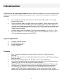
Table of Contents
Page
Introduction
4
Chapter 1:
Installation
1) The Multiplexer Address Selection
2) The Card Address Selection
3) The A/D Card Input Channel Selection
4) The Power Supply
5) Installation
6
6
6
6
6
7
Chapter 2:
Interconnections
2.1) Connections to the Analog Card
2.2) the User Connector
2.4) The 64 Analog Input, Ground and Auxilliary
Screw-terminals
8
8
8
Chapter 3:
Sofware Guide
3.1) Obtaining a sample
3.2) PC-81A Settling Time
10
10
10
Chapter 5:
Repair Service
16
Chapter 6:
Hardware Specifications
17
Chapter 7:
Error Analysis
7.1) Multiplexer leakage current
7.2) Parallel operation
7.3) Sub-multiplexed mode operation
18
18
18
18
Chapter 8:
PC-26/30AT Considerations
19
Appendix A: PCB Layout Diagram
9
20
3
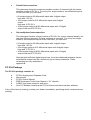
Introduction
The PC-81A is an analog input expander card. It has been designed to allow extra analog input
channels to be added to virtually any analog input card. In order for it to operate, it requires the
following:
¯
The existing analog input card must have at least two differential, or four single
ended analog inputs.
¯
There must be at least four digital output lines available. These digital output lines
need not be a part of the analog input card, but can be from any other card (or, if
desired, from a mechanical switch!). Users of PC/XT/AT machines can easily use a
low cost PC-36A/B/C parallel interface card if their analog input cards do not have
digital outputs available.
¯
A power supply must be available. This must have voltages of +/- 12V to +/- 15V
and +5V available. If no +5V is available, then it can be obtained from the +12V to
+15V by setting two jumpers on the PC-81A.
Typical applications
¯
¯
¯
¯
Complex Process Control
Laboratory Automation
Energy Management
Product Testing
Features
¯
¯
¯
¯
¯
¯
Four 16 channel multiplexers, giving 64 single ended or 32 differential input
channels.
Each PC-81A card can be individually addressed (card 0 to card 255), by setting an
8way dip switch
There are four analog outputs per PC-81A, one for each multiplexer.
As most analog input cards have sixteen input channels, any four of these can be
selected on the PC-81A by using the on-board jumpers.
Multiple PC-81A’s can be interconnected in a multitude of fashions. The two major
techniques are: Parallel Interconnection and Sub-Multiplexed Interconnection.
For simplicity with regards to cabling when using Parallel Interconnection, any
number of PC-81A’s can be “piggy-backed” (ie:one on top of the other), by the
adding male and/or female headers supplied in the mounting kit, to pcb location H4..
4
¯
Parallel Interconnection:
This technique allows the maximum possible number of channesl with the lowest
possible number of PC-81’s. For every four single ended or two differential inputs
on the host card, you can have:
s 64 single ended or 32 differential inputs with 4 digital output
lines and 1 PC-81;
s 1024 single ended or 512 differential inputs with 8 digital
output
lines and 16 PC-81’s.
s 16384 single ended or 8192 differential inputs with 12 digital
output lines and 256 PC-81’s
¯
Sub-multiplexed interconnection:
This technique requires a larger number of PC-81’s for a given channel density, but
has less effect on accuracy for large numbers of channels. For every four single
ended or two differential inputs on the host card, you can have:
s 64 single ended or 32 differential inputs with 4 digital output
lines and 1 PC-81.
s 1024 single ended or 512 differential inputs with 8 digital output
lines and 17 PC-81’s.
s 16384 single ended or 8192 differential inputs with 12 digital
output lines and 273 PC-81’s.
Note that with sufficient digital output lines, the sub-multiplexed technique can be
extended far further than this, limited only by accuracy constraints. These
constraints are fully described in
appendix B.
PC 81A Package
The PC-81A package consists of:
¯
¯
¯
¯
¯
¯
PC-81A Analog Input Expander Card
Mounting kit
PC-81A User's Manual
EDR Developers Toolkit User Manual + 3½” diskette
A DB37 type male connector and cover.
One 3½” diskette containing the PC-81A drivers and demonstration software
If any of the items is missing, contact your dealer immediately, specifying which components are
missing.
5
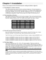
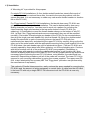
Chapter 1: Installation
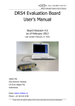
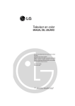
There are four aspects of the PC 81A that must be configured (Refer to figure 2):
1.1) The Multiplexer Address Selection
This address determines which of the four onboard multiplexers’ 16 input channels are
accessed. Address A0 to A3 are used for this purpose. The inputs to the multiplexers are
the 64 input channels, CH0 to CH63, and their 4 outputs are V0 to V3. For a differential
configuration, CH32 acts as the return for CH0, CH33 acts as the return for CH1, etc.
In differential configuration, output V2 is the return for V0 and V3 is the return for V1.
1.2) The Card Address Selection
This address determines which PC-81A card is accessed. This can be set by the 8-way
DIP switch found onboard. The address range in parallel mode is from PC-81A-(0) to PC81A-(255). Address lines A4 to A11 are used for this purpose. See figure 1 below:
DIP SWITCH
1
1
2
1
3
1
2
1
TO
DIP SWITCH
8
AND
2
AND
AND
TO
3
3
8
POSITION
OFF
ON
ON
ON
ON
ON
ON
ON
PC-81A
0
1
2
3
4
5
6
255
Figure 1: PC-81A 8-way DIP switch for card address setting
1.3) The A/D Card Input Channel Selection
Most A/D Multifunction Cards have 16 input channels. As the PC-81A has only 4 output
channels, normally 12 of the A/D cards’ input channels would not be used.
The PC-81A has four A/D Card Input Channel Selection headers, labelled BOARD 0 to 3.
Jumpers on BOARD 0 inserted, direct the four mutiplexer outputs to V0,V1,V2 & V3.
Jumpers on BOARD 1 inserted, direct the four mutiplexer outputs to V4,V5,V6 & V7.
Jumpers on BOARD 2 inserted, direct the four mutiplexer outputs to V8,V9,V10 & V11.
Jumpers on BOARD 3 inserted, direct the four mutiplexer outputs to V12,V13,V14 & V15.
1.4) The Power Supply
The PC-81A operates on +12V, -12V & +5V power supplies. These can usually be
obtained from the host A/D card. However, to allow for those cards which do not supply
+5V, the PC- 81A has an internal provision for the generation of this voltage.from the +12V
supply. Note that this considerably increases the power consumption of the PC-81A! The
internal +5V is enabled by inserting jumpers H 2 & H 3.
NOTE: THESE JUMPERS MUST NOT BE INSERTED IF THE HOST CARD SUPPLIES
+5V!
Certain host A/D cards do not have separate digital and analog ground. For these cards,
jumper H1 can be inserted. This connects the two together. It is not normally required, and
should be inserted only when absolutely necessary, as it’s use results in an increase in
noise levels.
6
1.5) Installation
A “Mounting kit” is provided.for this purpose.
For single PC-81A installations, fix four double-ended female hex stand-offs to each of
mounting holes on the card and there after, the card to the mounting cabinet, with the
screws provided. (It is not necessary to solder any male and/or female headers to location
H4 on the PC-81A.)
For “Piggy-backed” Parallel PC-81A installations, first decide how many PC-81A’s are
going to be used for your particular installation. This can be determined by how many
analog channels you require. You then need to work out a pattern for mounting the
interconnecting single row headers to the top and/or bottom of each PC-81A, (by
soldering). It is advisable to mount the female header always on the bottom of any PC81A, (so that if the “Piggy-backed cards are ever seperated, they can still be mounted
normally). First solder a female single row header to the PC-81A to be mounted above,
then plug the single row male header fully into that female. By fixing four double-ended
female hex stand-offs to each of mounting holes on the lower PC-81A with four
male/female hex stand-offs, and attaching the upper PC-81A by carefully lining up the the
other end of the male header with the appropriate mounting holes of pcb location H4 on the
PC-81A below, the male header can now be soldered into place. (The two PC-81A’s are
correctly spaced by these stand-offs) After soldering, cut off the protruding pins. Continue
with this procedure until all of the proposed PC-81A’s are prepared. (Remember to
alternate rows with regards to mounting male/female headers to pcb location H4). Now
connect all analog input wires to the lower PC-81A. Set any jumpers and/or dip switches as
necessary before mounting the next PC-81A above, using another four male/femal hex
stand-offs. Repeat this procedure until all of the cards are mounted. The lower PC-81A is
secured to your mounting cabinet/box by using four screws supplied. The upper-most PC81A. is also attached by four screws.(NB! This “Piggy-back” procedure can performed by
the manufacturer if requested.)
This method of Parallel Interconnection, vastly reduces the space needed for mounting the
PC-81A’s and the amount of wiring necessary to control them. A cable from the A/D card
in the host PC with only a single DB-37 FM connector to all the PC-81A’s is now only
necessary.
7
8
CHAPTER 2: Interconnections
The PC-81A can be connected to any analog input card which has at least four (preferably
sixteen) A/D channels and twelve TTL output lines.
2.1) Connections to the analog card
All data transfers to the host analog card are channelled via a screened cable from the
PC-81A’s User Connector.
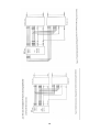
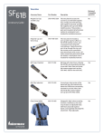
2.2) The User Connector
The PC-81A interfaces to the external world via a 37 way D-type male connector. This
connector acommodates the following signals:
¯ 16 separate analog output signals (V0 - V15)
¯ 12 address lines (A0 - A11)
¯ +5V, +12V, -12V, AGND & DGND
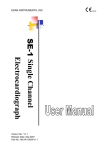
Figure 3: PC-81A User Connector
(as seen from the front)
Figure 3 graphically shows the connector together with their pin assignments. Note that the
pin connections refer to the pin numbers of the connector when looking into the connector
from the front. The square pad of the pcb component at location P1 represents pin1. Also
note that the pin numbers are embossed on the connector itself, but please note that
sometimes the connector manufacturers do make mistakes.
2.3) The 64 Analog Input, Ground and Aux Screw-terminals
Each of the sixty four analog inputs is multiplexed and redirected via the BOARD 0 - 3
headers to the User Connector.
The Auxilliary Screw-terminal connector includes (A0 - A11), (V0 - V3 and AGND) and
(+5V,+12V, -12V and DGND).
9
10
11
Chapter 3: Software Guide
This chapter discusses the software considerations necessary for A/D host cards which use the
PC-81A.
3.1) Obtaining an A/D Sample
The steps required to obtain an A/D sample are as follows:
I) Set the A/D card input channel.
II) Set the PC-81A channel.
III) Wait for the PC-81A to settle.
IV) Trigger the A/D converter in the A/D host card.
V) Wait for the A/D conversion to complete.
VI) Read in the result.
A demonstration program, PC-81A.--- supplied on the disk included with the PC-81A, shows
how this is done. This program is written in ------------- and displays -------(finish this later).
3.2) PC-81A Settling Time
As may be seen from the above, the major software consideration in using the PC-81A is the
seetling time..
When using only an A/D card, the settling time of the cards’s internal multiplexer is included
in the card’s conversion time, and hence does not require any attention. If a PC-81A is used
however, the settling time of the multiplexers on the PC81A must be taken into account. This
is normally done by a timing loop, although certain A/D cards have timers on board which
could be used for this purpose. The use of a timing loop is shown in the demonstration
program. (finish this later)
The actual settling time of the PC-81A is dependant on several factors, namely:
¯ Cable length - The longer the cable between the PC-81A and the A/D host card, the
longer the settling time.
¯ Source resistance - The effect of the cable is mainly to increase capacitance , which
must be charged from the voltage to be measured. The higher the source
impedance, the longer this will take.
¯ PC-81A configuration - When using multiple PC-81A’s, the way in which they are
connected significantly effects the settling time . In general, the settling time of submultiplexed PC-81A’s is significantly lower than that of parallel PC-81A’s.
The following figures may be taken as general guidelines for applications which use
relatively short cables (less than 1 metre in length).
¯ For a single PC-81A - approximately 5uS.
¯ For multiple PC-81A’s in sub-multiplexed mode - add 5uS for each layer of
PC-81A’s.
¯ For multiple PC-81A’s in parallel mode - add 2uS for each PC-81A.
12
Chapter 4: Driver Software
Full driver software is supplied with the PC 63C package. Full details are explained in the EDR
Software developers kit User Manual. A summary of what these drivers consist of are explained
below.
Both DOS and Windows Languages are supported: They are:
DOS Languages:
Borland C/C++ Version 3.1 or 4.0
Microsoft C/C++ Version 6.0 or 7.0
Borland Pascal / Turbo Pascal Version 6.0 or 7.0
Microsoft QuickBasic Version 4.5
National Instruments LabWindows Version 2.0
Windows Languages:
Borland C/C++ 3.1 or 4.0
Microsoft C/C++ 6.0 or 7.0
Borland Pascal / Turbo Pascal Version 6.0 or 7.0
4.1) Board Handles
All EDR functions used above require a board handle as the first parameter. The board
handle defines which board is affected by the function call. Using this method has several
advantages, For example, there is no need for a 'select board' function; working with parallel
boards is much easier; different applications using the EDR at the same time will not conflict
with each other.
Board handle are integers obtained by calling EDR_AllocBoardHandle (see 7.2 of EDR
Developers Toolkit). Once allocated a board handle must be initialised to the PC 63C before
it can be accessed. this is achieved by calling EDR_InitBoard or EDR_InitBoardType (see
7.5 of EDR manual) with the base address or EDR_loadConfiguration (see section 7.8 of
EDR manual).
EDR_InitBoard will attempt to detect the PC63C at the base address specified.
4.2) Interrupt functions
Since the external trigger line on the PC 63C is connected to a hardware interrupt, an ISR
can be installed using the EDR driver functions provided.
These functions are only callable from C/C++ or Borland/Turbo Pascal.
13
4.3) Quick Function Reference
The PC 63C Enhanced Reed Relay Board utilises the following functions calls contained in
the EDR driver developers toolkit. They are:
Function Name
EDR_DIOPortOutput
EDR_DIOPortInput
EDR_DIOLineOutput
EDR_DIOLineOutput
EDR_InstallISR
EDR_UninstallISR
EDR_InstallBoardISR
EDR_UninstallBoardISR
EDR_MaskIRQ
EDR_MaskBoardIRQ
EDR_EnableInterrupt
EDR_ResetInterrupt
EDR_AllocBoardHandle
EDR_FreeBoardHandle
EDR_InitBoardType
EDR_ConfigDialog
EDR_SaveConfiguration
EDR_LoadConfiguration
EDR_RestoreDefaults
EDR_IsBaseAddressInUse
EDR_DetectBoard
EDR_SetBoardType
EDR_SetIRQLevel
Description
Writes a byte of data to the PC63C I/O port
Reads a byte of data from the PC 63C I/O Port. If the port
is an output port then the last value written to the port is
returned.
Changes a single line (bit) on the PC63C I/O port. This in
turn switches one the reed relays (ON/OFF) on the PC
63C.
Obtains the status of a single line in a digital I/O port on the
PC 63C. This function determines whether any one of the
reed relays is ON/OFF.
Installs an ISR for the specified hardware interrupt request
Removes an interrupt service routine that was installed
with EDR_InstallISR
Installs an ISR for a particular type of interrupt installed on
the PC 63C.
Removes an interrupt service routine that was installed
with EDR_InstallBoardISR
Masks or unmasks a particular IRQ level
Masks or unmasks a particular board interrupt
Enables / disables a specified interrupt on hte PC 63C
Resets an interrupt latch on the PC 63C and sends an EOI
command to one of the PCs interrupt controllers on
completion of the interrupt
Allocates a new board handle to the PC 63C. If no board
handles are available then a 0 is returned. This is
particularly useful is multiple PC 63C are present in the
same.computer.
Releases a board handle allocated to the PC 63C making it
available to any other PC card
Initialises a board and allocates a board handle to it
Diplays a dialog box that allows the user to manually
configure the driver for the Board in the computer
Function writes configuration information to a file for later
loading with EDR_LoadConfiguration
Loads details of the Cards configuration from the file
created by EDR_SaveConfiguration
Restores factory default configuration for a baord attached
to a handle
Checks if any board initialised with EDR is using the
specified I/O address
Tries to determine the type of board present at a specified
I/O address.
Changes the board type attached to a board handle
Set the IRQ level EDR will use for the interrupt ID
specified.
14
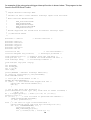
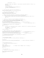
An example of the using external trigger interrupt function is shown below. This program is also
found in the EDR Driver Toolkit.
/*
* Simple external interrupt demo.
*
* Installs an ISR to count external interrupt inputs from the board.
*
* Main functions demonstrated:
*
*
EDR_InstallBoardISR
*
EDR_MaskBoardIRQ
*
EDR_EnableInterrupt
*
EDR_UninstallBoardISR
*
EDR_ResetInterrupt
*
* Boards supported: All boards with an external interrupt input.
*
* (c)1994 David Tinker
*/
#include "..\edr.h"
#include
#include
#include
#include
#include
#include
/* driver functions */
<stdio.h>
<stdlib.h>
<conio.h>
<ctype.h>
<string.h>
<dos.h>
volatile int bh;
volatile unsigned long icount=0;
/* our board handle */
/* interrupts processed */
void printerror(int r); /* displays error msg and exits */
void quit(int c);
/* release our board handle and exit */
void interrupt ISR();
/* our interrupt handler */
void main(int argc,char *argv[])
{
int baseaddr;
int boardtype;
int i,j,k,ch;
char s[80];
printf("EXTINT - External interrupt demo\n\n");
if (argc==2) sscanf(argv[1],"%x",&baseaddr);
else baseaddr=0x300;
/* first get a board handle to use */
bh=EDR_AllocBoardHandle();
if (!bh) { /* this should never happen with DOS */
printf("No free board handles\n");
exit(1);
}
/* ask if user wants auto detection */
printf("Autodetect board type (only works with no cables attached) "
"(Y/N) ?");
do { i=toupper(getch()); } while ((i!='Y') && (i!='N'));
printf(" %c\n",i);
if (i=='Y') {
/* look for board at specified base address */
i=EDR_InitBoard(bh,baseaddr);
if (i<0) printerror(i);
}
else { /* ask user for type of installed board */
printf("Choose board type from the following list:\n");
for (i=1; i<NUMBOARDTYPES; i++) {
sprintf(s,"%02d ",i);
EDR_StrBoardType(i,s+3);
for (; strlen(s)<14; ) strcat(s," ");
15
printf("%s ",s);
}
printf("\nType the number of the board installed (enter to exit): ");
gets(s);
i=atoi(s);
if (!i) quit(1);
i=EDR_InitBoardType(bh,baseaddr,i);
if (i<0) printerror(i);
}
/* let the user chose the base address */
EDR_ConfigDialog(bh,-1,-1,-1,-1,-1,-1,-1);
/* copy the board type into a var */
EDR_GetBase(bh,&baseaddr);
EDR_GetBoardType(bh,&boardtype);
/* make sure this board has an external interrupt input */
if (!EDR_ValidInterruptID(boardtype,EDR_INT_EXTINPUT)) {
printf("This board does not have an external interrupt input.\n");
quit(1);
}
/* install our ISR for first external interrupt */
/* the second would be EDR_INT_EXTINPUT+1 and so on */
j=EDR_InstallBoardISR(bh,EDR_INT_EXTINPUT,ISR);
if (j<0) printerror(j);
EDR_MaskBoardIRQ(bh,EDR_INT_EXTINPUT,0); /* unmask the IRQ */
EDR_EnableInterrupt(bh,EDR_INT_EXTINPUT,1);
/* start generating ints */
/* display count until esc is pressed */
printf("\n");
do {
printf("%lu interrupts have occured - press esc to exit%c",icount,13);
if (kbhit()) ch=getch();
else ch=0;
} while (ch!=27);
printf("\n\n");
/* undo interrupt stuff (very important!) */
EDR_EnableInterrupt(bh,EDR_INT_EXTINPUT,0);
/* stop generating ints */
EDR_MaskBoardIRQ(bh,EDR_INT_EXTINPUT,1); /* mask the IRQ */
EDR_UninstallBoardISR(bh,EDR_INT_EXTINPUT);
/* remove our ISR */
/* release the board handle (not necessary for DOS) */
EDR_FreeBoardHandle(bh);
}
void interrupt ISR()
/* this gets called for every external interrupt */
{
icount++;
EDR_ResetInterrupt(bh,EDR_INT_EXTINPUT); /* signal interrupt complete */
}
void printerror(int r)
/* displays error msg and exits */
{
char s[80];
EDR_StrError(r,s);
/* convert error number into a string */
printf("%s\n",s);
quit(1);
}
void quit(int c)
/* release our board handle and exit */
{
EDR_FreeBoardHandle(bh);
exit(c);
}
16
Chapter 5: Repair Service
The PC-81A is guaranteed for a period of 1 year. If the board is faulty within this period, we
will gladly repair it free of charge provided that the maximum specifications was not exceeded.
If any burn't tracks are seen on the PC-81A Card or any of the multiplexers are blown, the
warranty will be void. A repair charge will then be levied if the user requires the board to be
repaired.
Our repair service centre will be available to repair our products even after the 1 year
warranty. A reasonable service fee will be levied which usually covers the cost of the
components that are faulty and the labour cost per hour or part thereof.
17
Chapter 6: Specifications
Number of channels:
64 Single-ended, 32 Differential.
Resistance, input to output:
2K Ohm channel ON, 100M Ohm channel OFF.
Input capacitance:
20pF (max)
Output capacitance:
20pF (max)
Leakage current, inputs:
5nA (max) @ 25º C, 100nA (max) @ 70º C.
Leakage currrent, outputs:
5nA (max) @ 25º C, 100nA (max) @ 70º C.
Settling time:
1.5uS (max) with a 10 Ohm source impedance and a
50pF load.
Minimum host impedance:
100M Ohm.
Digital inputs:
TTL compatible, 100uA (max) leakage current.
Power supply current, +12V:
4mA (max), with internal +5V power supply disabled.and
10mA (max), with internal +5V power supply enabled.
Power supply current, -12V:
4mA (max).
Power supply current, +5V:
500uA (max).
Power supply range, +12V:
+11.5V to +15V.
Power supply range, -12V:
-11.5V to -15V.
Power supply range, +5V:
+4.5V to +5.5V.
18
Chapter 7: Error Analysis
Any extra components in the signal path of a data acquisition system will result in
measurement errors. In the case of the PC-81A, and multiplexers in general. it is the effect
of the leakage current which is by far the most significant cause. This is especially the case
for large numbers of multiplexers.
7.1) Multiplexer leakage current
All multiplexers have some leakage current. For most multiplexers, including those uesd on
the PC-81A , this is strongly temperature dependant, typically doubling every10º C. For this
reason, leakage currents are specified both at 25º C and at 70º C. For the PC-81A, and
almost all multiplexers used on A/D cards, maximum current at 25º C is 1nA.
7.2) Parallel operation
For parallel operation, the error due to leakage can be calculated as follows:
Verr = (Nm + 2) (Rm + Rs) Im
where:
Verr - is the error voltage due to leakage current;
Nm - is the number of PC-81A’s;
Rm - is the PC-81A’s ON resistance;
Rs - is the source resistance;
Im - is the PC-81A leakage current.
Note that this calculation assumes that the A/D card contains a similar multiplexer to that in
the PC-81A. This is almost always the case.
7.3) Sub-multiplexed mode operation
For sub-multiplexed mode operation, the error due to leakage can be calculated as follows:
Verr = (N1 (N1 + 1) Rm / 2 + N1Rs) Im
where:
Verr - is the error voltage due to leakage current;
N1 - is the number of layers of multiplexers (including the multiplexer on the
host A/D card);
Rm - is the PC-81A’s ON resistance;
Rs - is the source resistance;
Im - is the PC-81A leakage current.
Note that this calculation assumes that the A/D card contains a similar multiplexer to that in the
PC-81A, and that this calculation uses the number of layers of multiplexers, NOT the number of
multiplexers. For example, in the the figure ----(still not finished), N1 would be 3.
Note also that because the error in the case of sub-multiplexed mode operation is dependant on
the number of layers, rather than the number of multiplexers, errors for sub-multiplexed mode
operation are considerably lower if large numbers of channels are used.
19
-
Chapter 8: PC-26/30AT Considerations
For users of the older PC-26/30AT data acquisition cards, certain special considerations apply.
PC-26/30AT cards have built-in termination resistors, in order to prevent errors due to open
inputs. These termination resistors must be removed to allow operation in conjunction with a PC81A.
The components in question are the 22K Ohm resistor arrays R9 and R10, and the discrete 22K
Ohm resistors R6 and R7. We recommend removal by simply cutting the leads of these
components on the component side of the board. Attempting to de-solder the components is NOT
recommended, unless you are an experienced technician with the correct equipment for the job.
20
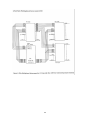
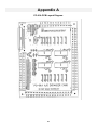
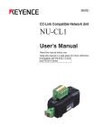
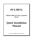
Appendix A
PC-81A PCB Layout Diagram
21