1
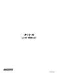
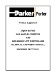
Hammer Union Pressure Transmitter User Manual For The HU-L24 & HU-L27 APG R Doc #9002480 Rev B2, 02/15 Table of Contents Introduction................................................................................................................. iii Warranty and Warranty Restrictions..................................................................... iv Chapter 1: Specifications and Options..................................................................... 1 Dimensions.........................................................................................................................................1 Specifications.....................................................................................................................................1 Model Number Configurator........................................................................................................... 2 Electrical Connectors and Pinout Table...................................................................................... 3 Chapter 2: Installation and Removal Procedures and Notes...............................4 Tools Needed...................................................................................................................................... 4 Physical Installation........................................................................................................................ 4 Electrical Installation...................................................................................................................... 4 Removal Instructions...................................................................................................................... 4 Chapter 3: Maintenance..............................................................................................5 General Care....................................................................................................................................... 5 Repair and Returns........................................................................................................................... 5 Chapter 4: Hazardous Location Installation and Certification...........................6 Intrinsically Safe Wiring Diagram................................................................................................ 6 CSA Certificate of Compliance....................................................................................................7-8 EC Declaration of Conformity........................................................................................................ 9 ii Tel: 1/888/525-7300 • Fax: 1/435/753-7490 • www.apgsensors.com • [email protected] Introduction Thank you for purchasing a Hammer Union Pressure Transmitter from APG. We appreciate your business! Please take a few minutes to familiarize yourself with your Hammer Union and this manual. APG’s Hammer Union Pressure Transmitter is extremely rugged and designed for the environments of landbased and offshore drilling installations. It is designed specifically for use with the 1502 and 2202 Hammer Wing Union. These units are constructed from materials designed for service with highly abrasive and corrosive media and comply with new NACE standards. Reading your label Every APG instrument comes with a label that includes the instrument’s model number, part number, serial number, and a wiring pinout table. Please ensure that the part number and pinout table on your label match your order. The following electrical ratings and approvals are also listed on the label. Please refer to the Certificate of Compliance and Declaration of Conformity at the back of this manual for further details. Electrical ratings Input: 10 to 28 VDC; Output: 4-20 mA / 0-5 VDC (per order) Class I, Division 1, Groups C, D Class I, Zone 0 Ex ia IIB T4: -40°C to 85°C; Enclosure Type IP67 AEx ia IIB T4: -40°C to 85°C; Enclosure Type IP67 Vmax Ui= 28VDC, Imax Ii = 110mA, Pmax Pi = 1W, Ci = 60.89nF, Li = 7.7mH The following approvals only apply to the L24 (4-20mA) version ATEX Directive: 0344 Sira 13ATEX2023 II 1G Ex ia IIB T4 Ga Ta: -40°C to 85°C Ui ≤ 28 V, Ii ≤ 110 mA, Pi ≤ 1 W, Ci ≤ 60.89 nF, Li ≤ 7.7 mH IECEx CSA 13.0004 Ex ia IIB T4 Ga IMPORTANT: Hammer Union Pressure Transmitter MUST be installed according to drawing 9002460 (Intrinsically Safe Wiring Diagram) on page 10 to meet listed approvals. Faulty installation will invalidate all safety approvals and ratings. Tel: 1/888/525-7300 • Fax: 1/435/753-7490 • www.apgsensors.com • [email protected] iii Warranty and Warranty Restrictions APG warrants its products to be free from defects of material and workmanship and will, without charge, replace or repair any equipment found defective upon inspection at its factory, provided the equipment has been returned, transportation prepaid, within 24 months from date of shipment from factory. THE FOREGOING WARRANTY IS IN LIEU OF AND EXCLUDES ALL OTHER WARRANTIES NOT EXPRESSLY SET FORTH HEREIN, WHETHER EXPRESSED OR IMPLIED BY OPERATION OF LAW OR OTHERWISE INCLUDING BUT NOT LIMITED TO ANY IMPLIED WARRANTIES OF MERCHANTABILITY OR FITNESS FOR A PARTICULAR PURPOSE. No representation or warranty, express or implied, made by any sales representative, distributor, or other agent or representative of APG which is not specifically set forth herein shall be binding upon APG. APG shall not be liable for any incidental or consequential damages, losses or expenses directly or indirectly arising from the sale, handling, improper application or use of the goods or from any other cause relating thereto and APG’s liability hereunder, in any case, is expressly limited to the repair or replacement (at APG’s option) of goods. Warranty is specifically at the factory. Any on site service will be provided at the sole expense of the Purchaser at standard field service rates. All associated equipment must be protected by properly rated electronic/electrical protection devices. APG shall not be liable for any damage due to improper engineering or installation by the Purchaser or third parties. Proper installation, operation and maintenance of the product becomes the responsibility of the user upon receipt of the product. Returns and allowances must be authorized by APG in advance. APG will assign a Return Material Authorization (RMA) number which must appear on all related papers and the outside of the shipping carton. All returns are subject to the final review by APG. Returns are subject to restocking charges as determined by APG’s “Credit Return Policy”. iv Tel: 1/888/525-7300 • Fax: 1/435/753-7490 • www.apgsensors.com • [email protected] Chapter 1: Specifications and Options • Dimensions Hammer Union with 2002, 2202 Fitting Automation Products Group, Inc. 888-525-7300 Model: HU-Lnn-IS-nnK-PSIS PN: nnnnnn-nnnn Serial #: . Automation Products Group, Inc. Mfg Date: . 888-525-7300 PN: nnnnnn-nnnn Model: HU-Lnn-IS-nnK-PSIS PN: nnnnnn-nnnn Serial #: . Mfg Date: . PN: nnnnnn-nnnn Hammer Union with 1502 Fitting • Specifications Performance Pressure Ranges Analog Output Over Pressure Burst Pressure Life 0 to 20K PSIS (Per Part Number) 4-20mA, 0-5VDC 1.5X Full Scale or limit of fitting, whichever is less 3.0X Full Scale or limit of fitting, whichever is less 10 million cycles, minimum Accuracy Linearity, Hystereses & Repeatability Thermal Zero Shift Thermal Span Shift ±0.25% of Full Scale (BFSL) ±0.026% FSO/°C (±0.01% FSO/°F) ±0.026% FSO/°C (±0.01% FSO/°F) Environmental Operating Temperature Compensated Temperature Enclosure Protection -40 to 85°C -40 to 65°C IP67 (-40 to 185°F) (-40 to 150°F) Electrical Supply Voltage Output Signal @ 21°C 10-28 VDC on sensor 4-20 mA: 3-30 mA max. 0 to 5 VDC: 7mA max Masterials of Construction Wetted Materials Enclosure Incoloy 925 NACE MR-01-75 and ISO 15156-3 316L Stainless Steel Mechanical Pressure Connection Weight WECO® standard 1502, 2002, 2202 or equivalent 2.3kg (5.10 lbs) Tel: 1/888/525-7300 • Fax: 1/435/753-7490 • www.apgsensors.com • [email protected] 1 • Model Number Configurator Part Number: HU - _____ - IS - _____ - PSIS - _____ - _____ - _____ A B C D E A. Output □ L24 □ L27 D. Fitting □ P34 □ P35 □ P36 □ P37 4-20 mA 0-5 VDC B. Pressure Range □ 5K □ 6K □ 10K □ 15K □ 20K 0 - 5,000 psis 0 - 6,000 psis 0 - 10,000 psis 0 - 15,000 psis 0 - 20,000 psis (2002 fitting only) Large HU 1502 Weco fitting Small HU 2002 / 2202 Weco fitting Large Welded HU 1502 Weco fitting Small Welded HU 2002 / 2202 Weco fitting E. Enclosure □ K0 □ K7 □ K1 No options (standard) With handle* With protective cage assembly* *Consult factory C. Electrical Connection 4-20 mA Output Options □ E1 □ E2 □ E6 □ E7 □ E8 □ E9 □ E11 □ E13 □ E15 □ E18 □ E20 □ E28 □ E40 □ E45 4 pin ‘Mini’ (w/ Shunt Cal) 5 pin ‘Mini’ (w/ Shunt Cal) 3 pin Turck Minifast [RSFVL36] 4 pin Reverse Bayonet (w/ Shunt Cal) 5 pin Threaded MS3102 (w/ Shunt Cal) 3 pin Threaded MS3102 4 pin Threaded MS3102 7 pin Jupiter/Souriau (w/ Shunt Cal) 6 pin Bayonet (w/ Shunt Cal) 4 pin Rota (w/ Shunt Cal) 4 pin Turck minifast [P-RSFV 40-0.3] 6 pin Bayonet 3 pin Bayonet (w/ Shunt Cal) 6 pin Bayonet (w/ Shunt Cal) 0-5 VDC Output Options □ E3 □ E14 4 pin Threaded MS3102 6 pin Bayonet (w/ Shunt Cal) 4-20 mA Direct Wiring Options □ E5 □ E10 □ E17 2 1/2 NPT coupling, flying leads Junction Box (1502 fitting only) 1/2 NPT coupling, 10’ cable, flying leads Tel: 1/888/525-7300 • Fax: 1/435/753-7490 • www.apgsensors.com • [email protected] • Electrical Connectors and Pinout Table Face view of male connector on HU + Signal C A C Red Wire – Signal A Black Wire B B 3-Pin Threaded MS3102 Connector Shunt Cal 3-Pin Bayonet Connector D A D A C B C B 4-Pin Threaded MS3102 Connector 4-Pin Reverse Bayonet Connector A A E D B C F B E C 4-Pin “Mini” Style Connector 5-Pin “Mini” Style Connector Turk Minifast RSFVL 36 Connector Turk Minifast P-RSFV 40-0.3 Connector Wire D 5-Pin Threaded MS3102 Connector Yellow Wire Flying Leads & Terminal Strip Wiring 4-20 mA Output Direct Wiring E5 E10 E17 Flying Lead Wires Junction Box (1502 only) Flying Lead Wires 1/2” NPTM Coupling 1/2” NPTF Cable Entry 1/2” NPTF Coupling Red + Signal + Signal Black – Signal – Signal + Signal – Signal Yellow Shunt Cal Shunt Cal Shunt Cal 6-Pin Bayonet Connector 0 to 5 VDC Output 4-20 mA Output E3 E14 E1 E2 E6 E7 4 pin MS3102 6 pin Bayonet 4 pin “Mini” Style 5 pin “Mini” Style 3 pin Turck 4 pin Bayonet Pin Electroplate Nickel Stainless Steel Nickel Plated Zinc Nickel Plated Zinc Stainless Steel Stainless Steel E8 5 pin MS3102 Stainless Steel E9 3 pin MS3102 Stainless Steel A (1) + Power + Power + Signal + Signal No Connection + Power/Signal No Connection No Connection B (2) – Power + Signal – Signal – Signal + Power/Signal – Power/Signal – Power/Signal + Power/Signal C (3) + Signal -Power Shunt Cal No Connection - Power/Signal Shunt Cal + Power/Signal - Power/Signal D (4) – Signal – Signal No connection Shunt Cal – No Connection Shunt Cal – E (5) – +Shunt Cal – No Connection – – No Connection – F – -Shunt Cal – – – – – – Note: Mating connectors sold separately. Pin E11 E13 E15 4 pin MS3102 7 Pin Jup./Souriau 6 pin Bayonet Stainless Steel Stainless Steel Stainless Steel 4-20 mA Output E18 E20 4 pin ROTA 4 pin Turck Stainless Steel Stainless Steel E28 6 pin Bayonet Stainless Steel E40 3 pin Bayonet Stainless Steel A (1) No Connection + Power/Signal + Power/Signal + Power/Signal -Power/Signal + Power/Signal + Power/Signal + Power/Signal B (2) – Power/Signal – Power/Signal – Power/Signal – Power/Signal + Power/Signal – Power/Signal – Power/Signal – Power/Signal C (3) + Power/Signal No Connection No Connection Case Ground No Connection No Connection Shunt Cal No Connection Case Ground No Connection – Case Ground E45 6 pin Bayonet Stainless Steel D (4) Case Ground No Connection Case Ground Shunt Cal E (5) – Shunt Cal + Shunt Cal – – No Connection – Shunt Cal F (6) – No Connection – Shunt Cal – – No Connection – No Connection G (7) – No Connection – – – – – – Note: Mating connectors sold separately. Tel: 1/888/525-7300 • Fax: 1/435/753-7490 • www.apgsensors.com • [email protected] 3 Chapter 2: Installation and Removal Procedures and Notes • Tools Needed You will need the following tools to install your 1502 or 2002 / 2202 Hammer Union Pressure Transmitter: • A hammer • 1502 or 2002 / 2202 wing nut DANGER: Mismatched unions and nuts can result in dangerous or hazardous equipment failures. Always check identifications on both union pieces and nuts prior to installation. Only use pieces with matching union figure numbers, sizes, and pressure ratings. • Physical Installation • • • • Ensure mating union faces are clean, dry, and free of debris. Mate your Hammer Union Pressure Transmitter onto the socket. Place the wing nut on the Transmitter and spin into place. Hammer the wing nut until tight. • Electrical Installation • Check the pinout table on your Hammer Union Pressure Transmitter against your order. • Check that your electrical system wiring matches the pinout table on your Hammer Union. • For instruments with connectors, make the connection. Otherwise, attach your wire to the provided terminal strip. Calibration Shunt Procedure APG’s Hammer Union Pressure Transmitters provide a true 20.0 mA calibration shunt output when 10 to 28 VDC is applied to the designated + Shunt Cal pin. See the pinout chart on your Hammer Union Pressure Transmitter’s label. For some standard pinouts, see Electrical Connectors and Pinout Table in Chapter 1. • Removal Instructions Removing your Hammer Union Pressure Transmitter from service must be done with care. It’s easy to create an unsafe situation if you are not careful to follow these guidelines: • Make sure the pressure is completely removed from the line where your sensor is installed. Follow any and all procedures for safely isolating any media contained inside the line or vessel. • Remove the Hammer Union wing nut. • Remove your Pressure Transmitter. • Clean the sensor’s fitting and diaphragm of any debris (see above instructions) and inspect for damage. • Store your sensor in a dry place, at a temperature between -40° F and 180° F. 4 Tel: 1/888/525-7300 • Fax: 1/435/753-7490 • www.apgsensors.com • [email protected] DANGER: Removing your Hammer Union Pressure Transmitter while there is still pressure in the line could result in injury or death. Chapter 3: Maintenance • General Care Your Hammer Union Pressure Transmitter is designed to be maintenance free. As such, there are no customer servicable parts on or in the device. However, in general, you should: • Avoid touching the diaphragm. Contact with the diaphragm, especially with a tool, could permanently shift the output and ruin accuracy. • Clean the diaphragm or the diaphragm bore only with extreme care. If using a tool is required, make sure it does not touch the diaphram. • Repair and Returns Should your Hammer Union Pressure Transmitter require service, please contact the factory via phone, email, or online chat. We will issue you a Return Material Authorization (RMA) number with instructions. • Phone: 888-525-7300 • Email: [email protected] • Online chat at www.apgsensors.com Please have your Hammer Union Pressure Transmitter’s part number and serial number available. See Waranty and Warranty Restrictions for more information. IMPORTANT: All repairs and adjustments of the Hammer Union Pressure Transmitter must be made by the factory. Modifing, disassembling, or altering the Hammer Union Pressure Transmitter on site is strictly prohibited. Tel: 1/888/525-7300 • Fax: 1/435/753-7490 • www.apgsensors.com • [email protected] 5 6 Ca/Co ≥ Ci + Ccable La/Lo ≥ Li + Lcable 3. Maximum non-hazardous area voltage must not exceed 250 V. 4. Install in accordance with the NEC (ANSI/NFPA 70) and ANSI/ISA RP12.6 (U.S. Locations) or Canadian Electrical Code, Part I (Canadian Locations). Voc/Uo ≤ Vmax/Ui Isc/Io ≤ Imax/Ii Po ≤ Pi 1. Barriers must be NRTL approved and must be installed in accordance with manufacturer’s instructions. 2. Barrier parameters must meet the following requirements: Automation Products Group, Inc. 888-525-7300 Model: HU-Lnn-IS-nnK-PSIS PN: nnnnnn-nnnn Serial #: . Mfg Date: . PN: nnnnnn-nnnn Chapter 4: Hazardous Location Installation and Certification • Intrinsically Safe Wiring Diagram Tel: 1/888/525-7300 • Fax: 1/435/753-7490 • www.apgsensors.com • [email protected] • CSA Certificate of Compliance Certificate of Compliance Certificate: 1916494 Master Contract: 237484 Project: 2703264 Date Issued: September 15, 2014 Issued to: Automation Products Group Inc 1025 West 1700 North Logan, UT 84321 USA Attention: Karl Reid The products listed below are eligible to bear the CSA Mark shown with adjacent indicators 'C' and 'US' for Canada and US or with adjacent indicator 'US' for US only or without either indicator for Canada only. Andrew Redeker Issued by: Andrew Redeker PRODUCTS CLASS 2258 04 CLASS 2258 84 - PROCESS CONTROL EQUIPMENT - Intrinsically Safe, Entity - For Hazardous Locations - PROCESS CONTROL EQUIPMENT - Intrinsically Safe, Entity - - For Hazardous Locations - Certified to US Standards Class I, Division 1, Groups C, D Class I, Zone 0 Ex ia IIB T4 AEx ia IIB T4 • Hammer Union, Model HU-Ln-IS (Where Ln = L1, L3, L24 or L27). Temperature Code Rating T4; Ambient range -40°C to +85°C; Enclosure Type: IP65 and IP67; Maximum Working Pressure: 20,000 PSI; Installed as per Drawing 9002460; Intrinsically Safe with the following Entity Parameters: Vmax, Ui = 28Vdc DQD 507 Rev. 2012-05-22 Page: 1 Tel: 1/888/525-7300 • Fax: 1/435/753-7490 • www.apgsensors.com • [email protected] 7 Certificate: 1916494 Master Contract: 237484 Project: 2703264 Date Issued: September 15, 2014 Imax, Ii = 110mA Pmax, Pi = 1W Ci = 60.89nF Li = 7.7mH Notes: 1. Suffixes are added to indicate options not affecting safety. 2. This device must be connected to a NRTL approved safety barrier (located in a safe area). Notes: APPLICABLE REQUIREMENTS C22.2 No 0 - 10 C22.2 No 142 - M1987 C22.2 No 157-92 C22.2 No. 60079-0:11 C22.2 No. 60079-11:14 C22.2 No. 60529:05 UL 916, 4th Edition UL 913, 8th Edition UL 60079-0:13 UL 60079-11:13 ANSI/IEC 60529:2004 DQD 507 Rev. 2012-05-22 8 General Requirements - Canadian Electrical Code Part II. Process Control Equipment. Intrinsically Safe and Non-Incendive Equipment for Use in Hazardous Locations. Explosive Atmospheres - Part 0: Equipment - General requirements Explosive Atmospheres – Part 11: Equipment protection by intrinsic safety "i" Degrees of protection provided by enclosures (IP Code) Energy Management Equipment Intrinsically Safe Apparatus and Associated Apparatus for use in Class I, II, III, Division 1, Hazardous (Classified) Locations. Electrical Apparatus for Explosive Gas Atmospheres Part 0: General Requirements Electrical apparatus for Explosive Gas Atmospheres Part 11: Intrinsic Safety “i” Degrees of Protection Provided by Enclosures (IP Code) Page: 2 Tel: 1/888/525-7300 • Fax: 1/435/753-7490 • www.apgsensors.com • [email protected] • EC Declaration of Conformity Tel: 1/888/525-7300 • Fax: 1/435/753-7490 • www.apgsensors.com • [email protected] 9 APG R Automation Products Group, Inc. Tel: 1/888/525-7300 • Fax: 1/435/753-7490 • www.apgsensors.com • [email protected]