1
bdiNDI
BDM interface for Nucleus™ Debugger
ColdFire
User Manual
Manual Version 1.00 for BDI2000
© 1992-2005 ABATRON AG
bdiNDI
BDM interface for Nucleus™ Debugger, BDI2000 (ColdFire)
User Manual
2
1 Introduction ................................................................................................................................. 3
1.1 BDI2000................................................................................................................................. 3
2 Installation ................................................................................................................................... 4
2.1 Connecting the BDI2000 to Target......................................................................................... 4
2.1.1 Changing Target Processor Type ................................................................................. 6
2.2 Connecting the BDI2000 to Power Supply............................................................................. 7
2.2.1 External Power Supply ................................................................................................. 7
2.2.2 Power Supply from Target System ............................................................................... 8
2.3 Status LED «MODE»............................................................................................................. 9
2.4 Connecting the BDI2000 to the Host ................................................................................... 10
2.4.1 Serial line communication .......................................................................................... 10
2.4.2 Ethernet communication ............................................................................................ 11
2.5 Installation of the Configuration Software ............................................................................ 12
2.6 Configuration ....................................................................................................................... 13
2.6.1 BDI2000 Setup/Update .............................................................................................. 14
3 Init List........................................................................................................................................ 16
4 BDI working modes................................................................................................................... 17
4.1 Startup Mode ....................................................................................................................... 18
4.1.1 Startup mode RESET ................................................................................................ 18
4.1.2 Startup Mode STOP................................................................................................... 18
4.1.3 Startup mode RUN..................................................................................................... 19
4.2 Breakpoint Mode ................................................................................................................. 19
4.2.1 Breakpoint Mode FREEZED ...................................................................................... 19
4.2.2 Breakpoint Mode LOOP ............................................................................................. 19
4.3 Workspace ........................................................................................................................... 21
5 Working with Nucleus ............................................................................................................... 22
5.1 Direct Commands ................................................................................................................ 22
5.1.1 Flash.Setup ................................................................................................................ 22
5.1.2 Flash.Erase ................................................................................................................ 23
5.1.3 Flash.Load ................................................................................................................. 24
5.1.4 Flash.Idle.................................................................................................................... 24
5.2 Download to Flash Memory................................................................................................. 25
6 Telnet Interface .......................................................................................................................... 28
7 Specifications ............................................................................................................................ 29
8 Warranty ..................................................................................................................................... 30
Appendices
A Troubleshooting ........................................................................................................................ 31
B Maintenance .............................................................................................................................. 32
C Trademarks ................................................................................................................................ 34
© Copyright 1992-2005 by ABATRON AG
V 1.00
bdiNDI
BDM interface for Nucleus™ Debugger, BDI2000 (ColdFire)
User Manual
3
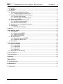
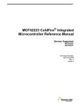
1 Introduction
Target System
Target System
ColdFire
ColdFire
BDM Interface
BDI2000
BDM Interface
BDI2000
PC Host
Nucleus
Abatron AG
Abatron AG
Swiss Made
RS232
Swiss Made
Ethernet (10 BASE-T)
The BDI2000 adds Background Debug Mode features to the Nucleus debugger environment from
Mentor Graphic’s. With the BDI2000, you control and monitor the microcontroller solely through the
stable on-chip debugging services. You won’t waste time and target resources with a software ROM
monitor, and you eliminate the cabling problems typical of ICE’s. This combination runs even when
the target system crashes and allows developers to continue investigating the cause of the crash.
A RS232 interface with a maximum of 115 kBaud and a 10Base-T Ethernet interface is available for
the host interface.
The configuration software is used to update the firmware and to configure the BDI2000 so it works
with the Nucleus debugger.
1.1 BDI2000
The BDI2000 is a processor system in a small box. It implements the interface between the JTAG
pins of the target CPU and a 10Base-T Ethernet / RS232 connector. The firmware and the programmable logic of the BDI2000 can be updated by the user with a simple Windows based configuration
program. The BDI2000 supports 1.8 – 5.0 Volts target systems (3.0 – 5.0 Volts target systems with
Rev. B).
© Copyright 1992-2005 by ABATRON AG
V 1.00
bdiNDI
BDM interface for Nucleus™ Debugger, BDI2000 (ColdFire)
User Manual
4
2 Installation
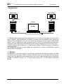
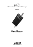
2.1 Connecting the BDI2000 to Target
The enclosed cable to the target system is designed for the Motorola recommended 26-pin Berg connector. In case where the target system has an appropriate connector, the cable can be directly connected. The pin assignment is in accordance with the Motorola specification.
!
In order to ensure reliable operation of the BDI (EMC, runtimes, etc.) the target cable length must not
exceed 20 cm (8").
Target System
Target Connector
Yellow Mark (Pin1)
ColdFire
1
25
2
26
BDI2000
BDI
Abatron AG
TRGT MODE
TARGET A
TARGET B
15
1
16
2
Swiss Made
The green LED «TRGT» marked light up when target is powered up
1 - NOT USED
2 - BKPT
3 - GROUND
4 - DSCLK
5 - GROUND
6 - NOT USED
7 - RESET
8 - DSI
9 - Vccio **
10 - DSO
11 - NOT USED
12 - NOT USED
13 - NOT USED
14 - NOT USED
15 - NOT USED
16 - NOT USED
17 - NOT USED
18 - NOT USED
19 - NOT USED
20 - NOT USED
21 - NOT USED
22 - NOT USED
23 - NOT USED
24 - CLK_CPU*
25 - Vcore **
26 - TEA
* only needed for V2 cores
** see note
The target CPU clock is only needed for older V2 cores (MCF5204, MCF5206(e) and MCF5272) because DSCLK and DSI have to change synchronous with the CPU clock. For all other cores, BDM
communication can be asynchronous to the CPU clock and therefore this signal is not needed.
Red Cable
!
Important note for older target cables:
The target cables delivered before October 2004
expect the target BDM reference voltage (Vccio) at
pin 25 of the BDM connector. For target boards
where Vccio is only routed to pin 9, remove the contact/wire from housing pin 25 and insert it into pin 9.
lift
Pin 9
Pin 25
© Copyright 1992-2005 by ABATRON AG
V 1.00
bdiNDI
BDM interface for Nucleus™ Debugger, BDI2000 (ColdFire)
User Manual
5
BDI TARGET B Connector Signals:
Pin
Name
1
DSO
2
<reseved>
3
DSI
4
<reseved>
5
<reseved>
6
Vcc Target
Describtion
DATA SERIAL OUT
For background debug mode, serial data output from the MCU.
DATA SERIAL IN
For background debug mode, serial data input signal to the MCU.
1.8 – 5.0V:
This is the target reference voltage. It indicates that the target has power and it is also used
to create the logic-level reference for the input comparators. It also controls the output logic
levels to the target. It is normally fed from Vdd I/O on the target board.
3.0 – 5.0V with Rev. B :
This input to the BDI2000 is used to detect if the target is powered up. If there is a current
limiting resistor between this pin and the target Vdd, it should be 100 Ohm or less.
7
DSCLK
DEVELOPMENT SERIAL CLOCK
For background debug mode, serial shift clock to the MCU.
8
BKPT
BREAKPOINT
BKPT is an active-low signal that signals a hardware breakpoint for the ColdFire core.
It is used to force the ColdFire core to enter debug mode.
9
TEA
(optional)
TRANSFER ERROR ACKNOWLEDGE (currently not implemented)
Active-low open-drain signal, used to abort a bus cycle.
This signal may be helpful for ColdFire devices which has no built-in bus monitor (e.g.
MCF5307). The BDI is able to terminate an invalid memory access. Otherwise BDM
communication may hang until a reset is applied.
10
<reseved>
11
<reseved>
12
GROUND
System Ground
13
RESET
RESET
Active-low open-drain signal, used to force a system reset.
14
CLK_CPU
PROCESSOR CLOCK
For some cores, this clock signal is used to synchonize the BDM signals DSCLK and DSI.
15
<reseved>
16
GROUND
System Ground
Pin 14 is only use for some older V2 cores (MCF5204, MCF5206(e) and MCF5272). For all other
cores this signal is not used.
© Copyright 1992-2005 by ABATRON AG
V 1.00
bdiNDI
BDM interface for Nucleus™ Debugger, BDI2000 (ColdFire)
User Manual
6
2.1.1 Changing Target Processor Type
Before you can use the BDI2000 with an other target processor type (e.g. ColdFire <--> PPC), a new
setup has to be done (see Appendix A). During this process the target cable must be disconnected
from the target system. The BDI2000 needs to be supplied with 5 Volts via the BDI OPTION connector (Rev. A) or via the POWER connector (Rev. B). For more information see chapter 2.2.1
«External Power Supply».
!
To avoid data line conflicts, the BDI2000 must be disconnected from the target system while
programming the logic for an other target CPU.
© Copyright 1992-2005 by ABATRON AG
V 1.00
bdiNDI
BDM interface for Nucleus™ Debugger, BDI2000 (ColdFire)
User Manual
7
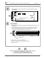
2.2 Connecting the BDI2000 to Power Supply
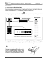
2.2.1 External Power Supply
The BDI2000 needs to be supplied with 5 Volts (max. 1A) via the POWER connector. The available
power supply from Abatron (option) or the enclosed power cable can be directly connected. In order
to ensure reliable operation of the BDI2000, keep the power supply cable as short as possible.
!
For error-free operation, the power supply to the BDI2000 must be between 4.75V and 5.25V DC.
The maximal tolerable supply voltage is 5.25 VDC. Any higher voltage or a wrong polarity
might destroy the electronics.
Rev. B Version
GND 3
1 Vcc
2
4
RS232
BDI
TRGT MODE
POWER
Connector
POWER
TARGET A
LI
TX RX
10 BASE-T
1 - Vcc (+5V)
2 - VccTGT
3 - GROUND
4 - NOT USED
TARGET B
The green LED «BDI» marked light up when 5V power is connected to the BDI2000
Please switch on the system in the following sequence:
• 1 --> external power supply
• 2 --> target system
© Copyright 1992-2005 by ABATRON AG
V 1.00
bdiNDI
BDM interface for Nucleus™ Debugger, BDI2000 (ColdFire)
User Manual
8
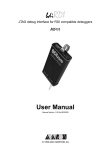
2.2.2 Power Supply from Target System
The BDI2000 needs to be supplied with 5 Volts (max. 1A) via TARGET B connector. This mode can
only be used when the target system runs with 5V and the pin «Vcc Target» is able to deliver a current
up to 1A@5V. For pin description and layout see chapter 2.1 «Connecting the BDI2000 to Target».
Insert the enclosed Jumper as shown in figure below. Please ensure that the jumper is inserted
correctly.
!
For error-free operation, the power supply to the BDI2000 must be between 4.75V and 5.25V DC.
The maximal tolerable supply voltage is 5.25 VDC. Any higher voltage or a wrong polarity
might destroy the electronics.
3
1
2
4
RS232
BDI
TRGT MODE
POWER
Connector
POWER
TARGET A
Jumper
LI
TX RX
10 BASE-T
1 - Vcc BDI2000 (+5V)
2 - Vcc Target (+5V)
3 - GROUND
4 - NOT USED
TARGET B
The green LEDs «BDI» and «TRGT» marked light up when target is powered up
and the jumper is inserted correctly
© Copyright 1992-2005 by ABATRON AG
V 1.00
bdiNDI
BDM interface for Nucleus™ Debugger, BDI2000 (ColdFire)
User Manual
9
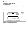
2.3 Status LED «MODE»
The built in LED indicates the following BDI states:
BDI
TRGT MODE
MODE LED
TARGET A
TARGET B
BDI STATES
OFF
The BDI is ready for use, the firmware is already loaded.
ON
The power supply for the BDI2000 is < 4.75VDC.
BLINK
The BDI «loader mode» is active (an invalid firmware is loaded or loading firmware is active).
© Copyright 1992-2005 by ABATRON AG
V 1.00
bdiNDI
BDM interface for Nucleus™ Debugger, BDI2000 (ColdFire)
User Manual
10
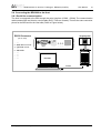
2.4 Connecting the BDI2000 to the Host
2.4.1 Serial line communication
The host is connected to the BDI through the serial interface (COM1...COM4). The communication
cable between BDI and Host is a serial cable (RXD / TXD are crossed). There is the same connector
pinout for the BDI and for the Host side (Refer to Figure below).
Target System
RS232 Connector
(for PC host)
12345
ColdFire
1 - NC
2 - RXD data from host
3 - TXD data to host
4 - NC
5 - GROUND
6 - NC
7 - NC
8 - NC
9 - NC
6789
RS232
POWER
LI
TX RX
10 BASE-T
BDI2000
PC Host
Abatron AG
Swiss Made
RS232
© Copyright 1992-2005 by ABATRON AG
V 1.00
bdiNDI
BDM interface for Nucleus™ Debugger, BDI2000 (ColdFire)
User Manual
11
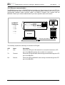
2.4.2 Ethernet communication
The BDI2000 has a built-in 10 BASE-T Ethernet interface (see figure below). Connect an UTP (Unshilded Twisted Pair) cable to the BD2000. For thin Ethernet coaxial networks you can connect a
commercially available media converter (BNC-->10 BASE-T) between your network and the
BDI2000. Contact your network administrator if you have questions about the network.
Target System
1
10 BASE-T
Connector
1 - TD+
2 - TD3 - RD+
4 - NC
5 - NC
6 - RD7 - NC
8 - NC
RS232
POWER
LI
TX RX
8
ColdFire
10 BASE-T
BDI2000
PC Host
Abatron AG
Swiss Made
Ethernet (10 BASE-T)
The following explains the meanings of the built-in LED lights:
LED
Name
Description
LI
Link
When this LED light is ON, data link is successful between the UTP
port of the BDI2000 and the hub to which it is connected.
TX
Transmit
When this LED light BLINKS, data is being transmitted through the UTP
port of the BDI2000
RX
Receive
When this LED light BLINKS, data is being received through the UTP
port of the BDI2000
© Copyright 1992-2005 by ABATRON AG
V 1.00
bdiNDI
BDM interface for Nucleus™ Debugger, BDI2000 (ColdFire)
User Manual
12
2.5 Installation of the Configuration Software
On the enclosed diskette you will find the BDI configuration software and the firmware required for
the BDI. Copy all these files to a directory on your hard disk.
The following files are on the diskette:
b20mcf.exe
Configuration program
b20mcf.hlp
Helpfile for the configuration program
b20mcf.cnt
Help contents file
b20mcffw.xxx
Firmware for BDI2000 for ColdFire targets
cf2jed20.xxx
JEDEC file for the BDI2000 (Rev. B) logic device (for old V2 cores)
cf2jed21.xxx
JEDEC file for the BDI2000 (Rev. C) logic device (for old V2 cores)
cf3jed20.xxx
JEDEC file for the BDI2000 (Rev. B) logic device
cf3jed21.xxx
JEDEC file for the BDI2000 (Rev. C) logic device
bdiifc32.dll
BDI Interface DLL for configuration program
*.bdi
Configuration Examples
Example of an installation process:
• Copy the entire contents of the enclosed diskette into a directory on the hard disk.
• You may create a new shortcut to the b20mcf.exe configuration program.
© Copyright 1992-2005 by ABATRON AG
V 1.00
bdiNDI
BDM interface for Nucleus™ Debugger, BDI2000 (ColdFire)
User Manual
13
2.6 Configuration
Before you can use the BDI together with the debugger, the BDI must be configured. Use the SETUP
menu and follow the steps listed below:
• Load or update the firmware / logic, store IP address
--> Firmware
• Set the communication parameters between Host and BDI
--> Communication
• Setup an initialization list for the target processor
--> Initlist
• Select the working mode
--> Mode
• Transmit the configuration to the BDI
--> Mode Transmit
For information about the dialogs and menus use the help system (F1).
© Copyright 1992-2005 by ABATRON AG
V 1.00
bdiNDI
BDM interface for Nucleus™ Debugger, BDI2000 (ColdFire)
User Manual
14
2.6.1 BDI2000 Setup/Update
First make sure that the BDI is properly connected (see Chapter 2.1 to 2.4). The BDI must be connected via RS232 to the Windows host.
!
To avoid data line conflicts, the BDI2000 must be disconnected from the target system while
programming the logic for an other target CPU (see Chapter 2.1.1).
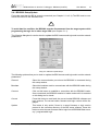
The following dialogbox is used to check or update the BDI firmware and logic and to set the network
parameters.
dialog box «BDI2000 Update/Setup»
The following options allow you to check or update the BDI firmware and logic and to set the network
parameters:
Channel
Select the communication port where the BDI2000 is connected during
this setup session.
Baudrate
Select the baudrate used to communicate with the BDI2000 loader during
this setup session.
Connect
Click on this button to establish a connection with the BDI2000 loader.
Once connected, the BDI2000 remains in loader mode until it is restarted
or this dialog box is closed.
Current
Press this button to read back the current loaded BDI2000 software and
logic versions. The current loader, firmware and logic version will be displayed.
Update
This button is only active if there is a newer firmware or logic version
present in the execution directory of the BDI setup software. Press this
button to write the new firmware and/or logic into the BDI2000 flash memory / programmable logic.
© Copyright 1992-2005 by ABATRON AG
V 1.00
bdiNDI
BDM interface for Nucleus™ Debugger, BDI2000 (ColdFire)
User Manual
15
Synch
Because some older V2 ColdFire cores (e.g. MCF5272) need synchronous signals at the BDM interface, the BDI uses a different logic for this
cores. Check this box only if your target is a MCF5204, MCF5206,
MCF5206e or MCF5272. The BDI automatically selects the correct JEDEC file. Make sure that there is the correct logic loaded for the target
CPU you are using.
IP Address
Enter the IP address for the BDI2000.
Use the following format: xxx.xxx.xxx.xxxe.g.151.120.25.101
Ask your network administrator for assigning an IP address to this
BDI2000. Every BDI2000 in your network needs a different IP address.
Subnet Mask
Enter the subnet mask of the network where the BDI is connected to.
Use the following format: xxx.xxx.xxx.xxxe.g.255.255.255.0
A subnet mask of 255.255.255.255 disables the gateway feature.
Ask your network administrator for the correct subnet mask.
Default Gateway
Enter the IP address of the default gateway. Ask your network administrator for the correct gateway IP address. If the gateway feature is disabled,
you may enter 255.255.255.255 or any other value..
Transmit
Click on this button to store the network configuration in the BDI2000 flash
memory.
In rare instances you may not be able to load the firmware in spite of a correctly connected BDI (error
of the previous firmware in the flash memory). Before carrying out the following procedure, check
the possibilities in Appendix «Troubleshooting». In case you do not have any success with the
tips there, do the following:
• Switch OFF the power supply for the BDI and open the unit as
described in Appendix «Maintenance»
• Place the jumper in the «INIT MODE» position
• Connect the power cable or target cable if the BDI is powered
from target system
• Switch ON the power supply for the BDI again and wait until the
LED «MODE» blinks fast
INIT MODE
• Turn the power supply OFF again
DEFAULT
• Return the jumper to the «DEFAULT» position
• Reassemble the unit as described in Appendix «Maintenance»
© Copyright 1992-2005 by ABATRON AG
V 1.00
bdiNDI
BDM interface for Nucleus™ Debugger, BDI2000 (ColdFire)
User Manual
16
3 Init List
dialog box «Startup Init List»
In order to prepare the target for debugging, you can define an Initialization List. This list is stored in
the Flash memory of the BDI2000 and worked through every time the target comes out of reset. Use
it to get the target operational after a reset. The memory system is usually initialized through this list.
After processing the init list, the RAM used to download the application must be accessible.
Use on-line help (F1) and the supplied configuration examples on the distribution disk to get more
information about the init list.
Special BDI Configuration Registers:
In order to change some special configuration parameters of the BDI, the WCREG entry in the init
list is used. Control register numbers greater than 0x8000 are used to set BDI internal registers:
8001
This entry in the init list allows to define a delay time (in ms) the BDI inserts between releasing the reset line and starting communicating with the target. This delay is necessary when
a target needs some wake-up time after a reset.
8002
This entry in the init list allows to define a time (in ms) the BDI asserts the hardware reset
signal. By default the reset signal is asserted for about 1ms.
© Copyright 1992-2005 by ABATRON AG
V 1.00
bdiNDI
BDM interface for Nucleus™ Debugger, BDI2000 (ColdFire)
User Manual
17
4 BDI working modes
dialog box «BDI Working Mode»
With this dialog box you can define how the BDI interacts with the target system.
Identification
Enter a text to identify this setup. This text can be read by the debugger
with the appropriate Command.
Startup
Startup mode defines how the BDI interacts with the target processor after
reset or power up. The options RESET, STOP or RUN can be selected.
Breakpoint
Breakpoint mode defines how breakpoints are processed. The target processor may be frozen (FREEZED option) or may be set to loop in an exception procedure (LOOP option) while the application software is halted.
Workspace
In all configurations except when «Use no target vectors» is activated, BDI
needs some target memory space. Enter here the start address of this
memory area. A maximum of 512 bytes is needed.
Vector base
The BDI needs to know where the vector table is located. Enter here the
start address of the vector table. This address is automatically loaded into
the VBR register at startup time. The application should not change the
VBR unless «Use no target vectors» is selected.
Loop Level
Selects the priority level (interrupt priority mask) the application uses
when halted in LOOP mode. A level of 7 disables all interrupts when the
application is halted. The value CURRENT(default) means, the application
loops with the level currently active at the point where it is stopped.
CPU Type
Select the appropriate CPU type.
CPU Clock Rate ...
Enter the clock rate which the target CPU runs, after BDI has worked
through the init list. BDI selects the BDM communication speed based on
this parameter. If this parameter selects a CPU clock rate that is higher
than the real clock, BDM communication may fail. When selecting a clock
rate slower than possible, BDM communication still works but not as fast
as possible.
© Copyright 1992-2005 by ABATRON AG
V 1.00
bdiNDI
BDM interface for Nucleus™ Debugger, BDI2000 (ColdFire)
User Manual
18
Use no target vectors
Check this switch if the BDI should not use any RAM or vectors in the target system. This option is only enabled when FREEZED is selected as
breakpoint mode. This mode is suitable for testing new hardware or debugging custom exception routines.
Use Breakpoint Logic
This switch defines how instruction breakpoints are implemented. When
not checked (default), instruction breakpoints are set as re-quested by the
debugger (Software or Hardware breakpoints). When checked, the BDI
uses always hardware breakpoints. This is useful when the attached debugger does not support hardware break-points.
4.1 Startup Mode
Startup mode defines how the BDI interacts with the target system after a reset or power up
sequence.
4.1.1 Startup mode RESET
In this mode no ROM is required on the target system. The necessary initialization is done by the BDI
with the programmed init list. The following steps are executed by the BDI after system reset or
system power up:
• RESET and BKPT are activated on the target system.
• RESET is deactivated and the target system changes to background debug mode.
• The BDI works through the initialization list and writes to the corresponding addresses.
• Depending on the break mode, the necessary vectors are set and help code is written into the
RAM on the target system.
The RESET mode is the standard working mode. Other modes are used in special cases (i.e.
applications in ROM, special requirements on the reset sequence...).
4.1.2 Startup Mode STOP
In this mode the initialization code is in a ROM on the target system. The code in this ROM handles
base initialization and sets the stackpointer. At the end of the code, the initialization program enters
an endless loop until it is interrupted by the BDI. This mode is intended for special requirements on
the reset sequence or, if, for example, separate hardware needs to be initialized immediately.
In this mode the following steps are executed by the BDI after system reset or power up:
• RESET and BKPT are activated on the target system.
• RESET is deactivated and the target system changes to background debug mode.
• The target CPU is started (the target starts at the address fetched when reading the start vector at address 0).
• The target system is working through the application code.
• After 2 seconds, BKPT is activated and the target system changes to background debug
mode.
• The BDI works through the initialization list and writes the corresponding addresses.
• Depending on the break mode, the necessary vectors are set and support code is written into
the RAM on the target system.
© Copyright 1992-2005 by ABATRON AG
V 1.00
bdiNDI
BDM interface for Nucleus™ Debugger, BDI2000 (ColdFire)
User Manual
19
4.1.3 Startup mode RUN
This mode is used to debug applications which are already stored in ROM. The application is started
normally and is stopped by the BDI as soon as the debugger connects to the BDI.
In this mode, the following steps are executed by the BDI after system reset or power up:
• RESET and BKPT are activated on the target system.
• RESET is deactivated and the target system changes to background debug mode.
• The target CPU is started (the target starts at the address fetched when reading the start vector at address 0).
• The target system is executing the application code.
• The application runs until the debugger stops the execution.
• BKPT is activated on the target system, and the target system changes to background
debug mode.
• Depending on the break mode, the necessary vectors are set and help code is written into the
RAM on the target system.
4.2 Breakpoint Mode
The use of software breakpoints is only possible if the application code is stored in RAM (not in ROM)
on the target system. Depending on the selected breakpoint mode, breakpoint and single step functions are implemented total differently.
4.2.1 Breakpoint Mode FREEZED
In this mode breakpoints are implemented by replacing application code with the HALT instruction.
All the time the application is halted (i.e. caused by a breakpoint) the target processor remains
freezed.
Single step is implemented by setting the appropriate bits (SSM, IPI) in the Debug Configuration/Status register and starting the CPU. Interrupts are ignored and debug mode is reentered after executing
exact one instruction.
4.2.2 Breakpoint Mode LOOP
In this mode breakpoints are implemented by replacing application code with a ILLEGAL instruction.
A stopped application loops within an exception procedure. The target processor is never freezed.
The priority level used when looping in the exception procedure can be defined using the option
«Loop Level». If you want to stop the hole application use Loop Level 7. If only the current task should
be stopped, use Loop Level CURRENT.
Single step is implemented by setting the Trace bit in the processor status register. So a single step
steps always over the current instruction. If interrupts are pending, they are served first without stopping the target processor.
The Loop mode is suitable when debugging real-time applications which can not be freezed, because
external interrupt must be handled even when an application task is stopped at a breakpoint.
© Copyright 1992-2005 by ABATRON AG
V 1.00
bdiNDI
BDM interface for Nucleus™ Debugger, BDI2000 (ColdFire)
User Manual
20
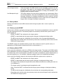
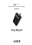
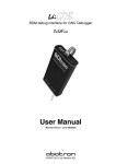
The following diagram shows the used universal exception procedure for ColdFire targets. May be
this helps you to understand how BDI works in LOOP mode.
Target
Vectortable:
BDI2000
Entry
save all register
write loop level
to status register
cleared
Test and clear
semaphore
set semaphore
set
store A7
The application loops here
when stopped.
Also, if interrupts are enabled
(Loop Level < 7), tasks with
lower priority will get no CPU
time because the stopped
task consumes it all.
no
restart flag
set ?
read stackframe pointer
BDI2000 firmware
set restart flag
yes
flush
instruction cache
Flushing the cache is not done for
devices with unified caches.
restore all registers
RTE
The ColdFire is never freezed because it is possible to access target memory via the BDM interface
while the CPU is running.
© Copyright 1992-2005 by ABATRON AG
V 1.00
bdiNDI
BDM interface for Nucleus™ Debugger, BDI2000 (ColdFire)
User Manual
21
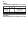
4.3 Workspace
Depending on the working mode, the BDI needs some RAM in the target system. The following table
shows how much RAM is used in the different modes.
Mode
Workspace
(Bytes)
Remark
RESET/FREEZED
4
needed to trap the exceptions
STOP/FREEZED
4
needed to trap the exceptions
RUN/FREEZED
4
needed to trap the exceptions
RESET/LOOP
512
used for standard exception procedure and the
initial (supervisor) stack
STOP/LOOP
256
used for standard exception procedure
RUN/LOOP
256
used for standard exception procedure
Vectors in RUN mode:
When RUN mode is selected, only the vectors 0... 24 are initialized when the application is halted for
the first time .
© Copyright 1992-2005 by ABATRON AG
V 1.00
bdiNDI
BDM interface for Nucleus™ Debugger, BDI2000 (ColdFire)
User Manual
22
5 Working with Nucleus
For information about using the Nucleus debugger look at the appropriate Nucleus user’s manual.
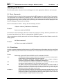
5.1 Direct Commands
For special functions (mainly for flash programming) the BDI supports so called «Direct Commands».
This commands can be entered in a codelet file (e.g. PRELOAD.CDL) or directly executed in the Nucleus Debugger Command Line Window. This Direct Commands are not interpreted by the Nucleus
Debugger but directly sent to the BDI. After processing the command the result is displayed in the
Nucleus Debugger Command Line Window.
Direct Commands are ASCII - Strings with the following structure:
<Object>.<Action> [<ParName>=<ParValue>]...
Example:
flash.erase addr=0x02800000
All names are case insensitive. Parameter values are numbers or strings. Numeric parameters can
be entered as decimal (e.g. 700) or as hexadecimal (0x80000) values.
If the commands are directly entered in the Nucleus Debugger Command Line Window, use the following syntax:
bdi "direct-command"
Example:
bdi "flash.erase addr=0x02800000"
5.1.1 Flash.Setup
In order to support loading into flash memory, the BDI needs some information about the used flash
devices. Before any other flash related command can be used, this direct command must be executed.
Syntax:
flash.setup type=am29f size=0x80000 bus=32 workspace=0x1000
type
size
bus
workspace
This parameter defines the type of flash used. It is used to select the correct programming algorithm. The following flash types are supported:
AM29F, AM29BX8, AM29BX16, I28BX8, I28BX16, AT49, AT49X8, AT49X16,
STRATAX8, STRATAX16, MIRROR, MORRORX8, MIRRORX16
The size of one flash chip in bytes (e.g. AM29F010 = 0x20000). This value is used to
calculate the starting address of the current flash memory bank.
The width of the memory bus that leads to the flash chips. Do not enter the width of
the flash chip itself. The parameter TYPE carries the information about the number of
data lines connected to one flash chip. For example, enter 16 if you are using two
AM29F010 to build a 16bit flash memory bank.
If a workspace is defined, the BDI uses a faster programming algorithm that run out of
RAM on the target system. Otherwise, the algorithm is processed within the BDI. The
workspace is used for a 1kByte data buffer and to store the algorithm code. There must
be at least 2kBytes of RAM available for this purpose.
© Copyright 1992-2005 by ABATRON AG
V 1.00
bdiNDI
BDM interface for Nucleus™ Debugger, BDI2000 (ColdFire)
User Manual
23
MCF5282 internal flash (CFM):
To erase and program the ColdFire Flash Module (CFM) you have to access it via the backdoor addresses (IPSBAR + 0x04000000). This backdoor address has to be used for erase and program commands. Before you can erase/program the CFM, the CFM Clock Divider needs to be setup via an init
list entry. Check the MCF5282 user’s manual about how to setup the CFMCLKD.
WM8
0x401D0002
0x54
;CFMCLKD : Flash clock divider for 64MHz
Syntax:
flash.setup type=cfm workspace=0x20000000
type
This parameter defines the type of flash used. Enter CFM when programming the
MCF5282 internal flash.
If a workspace is defined, the BDI uses a faster programming algorithm that run out of
RAM on the target system. Otherwise, the algorithm is processed within the BDI. The
workspace is used for a 1kByte data buffer and to store the algorithm code. There must
be at least 2kBytes of RAM available for this purpose.
workspace
;Use internal SRAM for workspace
bdi flash.setup type=cfm workspace=0x20000000
5.1.2 Flash.Erase
This command allows to erase one flash sector, block or chip.
Syntax:
flash.erase addr=0x02800000 mode=chip
addr
mode
The start address of the flash sector to erase.
This parameter defines the erase mode. The following modes are supported:
CHIP, BLOCK and SECTOR (default is sector erase)
MCF5282 internal flash (CFM):
This command allows to erase one flash sector (2k page) or one block (256k).
Syntax:
flash.erase addr=0x44000000 mode=block
addr
mode
The backdoor start address of the flash page/block to erase.
This parameter defines the erase mode. The following modes are supported:
BLOCK and SECTOR (default is sector (2k page) erase)
;Erase both blocks in a MCF5282
bdi flash.erase addr=0x44000000 mode=block
bdi flash.erase addr=0x44040000 mode=block
;Erase 2k page at 0x44000800 (0x44000800..0x44000FFF)
bdi flash.erase addr=0x44000800
© Copyright 1992-2005 by ABATRON AG
V 1.00
bdiNDI
BDM interface for Nucleus™ Debugger, BDI2000 (ColdFire)
User Manual
24
5.1.3 Flash.Load
This command enables loading to flash memory. If the address of a data block is within the given
flash range, the BDI automatically uses the appropriate programming algorithm. This command must
be executed before downloading is started.
Syntax:
flash.load addr=0x02800000 size=0x200000
addr
size
The start address of the flash memory
The size of the flash memory
5.1.4 Flash.Idle
This command disables loading to flash memory.
Syntax:
flash.idle
© Copyright 1992-2005 by ABATRON AG
V 1.00
bdiNDI
BDM interface for Nucleus™ Debugger, BDI2000 (ColdFire)
User Manual
25
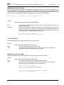
5.2 Download to Flash Memory
The BDI supports programming flash memory. To automate the process of downloading to flash
memory a codelet can be used. Following an example of such a codelet:
void flash_load(int coreId)
{
char output[256];
printf("Specifying the flash type...");
command("bdi flash.setup type=AM29F size=0x00800000 bus=8",output, 256);
printf("%s\n", output);
printf("Erasing the first sector...");
command("bdi flash.erase addr=0xfff00000 mode=sector", output,256);
printf("%s\n", output);
printf("Erasing the second sector...");
command("bdi flash.erase addr=0xfff10000 mode=sector", output,256);
printf("%s\n", output);
printf("Erasing the third sector...");
command("bdi flash.erase addr=0xfff20000 mode=sector", output,256);
printf("%s\n", output);
printf("Setting load address...");
command("bdi flash.load addr=0xfff00000 size=0x00020000",output, 256);
printf("%s\n", output);
printf("Loading the image...");
command("load C:\\MGC\\embedded\\Nucleus\\demo\\out\\plus_demo.out", output, 256);
printf("%s\n", output);
printf("Taking the BDI out of Flashing mode...");
command("bdi flash.idle", output, 256);
printf("%s\n", output);
}
A user who needs to reflash often can just call such a codelet from the Nucleus Debugger command
view by typing flash_load(1) at the command prompt. For this to work two steps are required:
1. The codelet file must first be loaded into EGDE.
• From the Run Menu select "Codelet Composer"
• On the Codelet Composer dialog click the Load button.
• Browse to and select your *.cdl file.
• To complete the operation click the Open button.
Alternatively, any *.cdl file that is simply imported into one of the user's projects will be identified by
Nucleus Debugger.
2. Since the flashing commands are issued over the debug connection, this of course requires that
a connection to already been established to the target.
In addition, the contents of the codelet can be placed in the user's initialization codelet and thus be
called automatically after connect.
© Copyright 1992-2005 by ABATRON AG
V 1.00
bdiNDI
BDM interface for Nucleus™ Debugger, BDI2000 (ColdFire)
User Manual
26
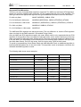
Supported Flash Memories:
There are currently 3 standard flash algorithm supported. The AMD, Intel and Atmel AT49 algorithm.
Almost all currently available flash memories can be programmed with one of this algorithm. The
flash type selects the appropriate algorithm and gives additional information about the used flash.
For 8bit only flash:
AM29F (MIRROR), I28BX8, AT49
For 8/16 bit flash in 8bit mode:
AM29BX8 (MIRRORX8), I28BX8 (STRATAX8), AT49X8
For 8/16 bit flash in 16bit mode:
AM29BX16 (MIRRORX16), I28BX16 (STRATAX16), AT49X16
For 16bit only flash:
AM29BX16, I28BX16, AT49X16
For 16/32 bit flash in 16bit mode: AM29DX16
The AMD and AT49 algorithm are almost the same. The only difference is, that the AT49 algorithm
does not check for the AMD status bit 5 (Exceeded Timing Limits).
Only the AMD and AT49 algorithm support chip erase. Block erase is only supported with the AT49
algorithm. If the algorithm does not support the selected mode, sector erase is performed. If the chip
does not support the selected mode, erasing will fail. The erase command sequence is different only
in the 6th write cycle. Depending on the selected mode, the following data is written in this cycle (see
also flash data sheets): 0x10 for chip erase, 0x30 for sector erase, 0x50 for block erase.
To speed up programming of Intel Strata Flash and AMD MirrorBit Flash, an additional algorithm is
implemented that makes use of the write buffer. This algorithm needs a workspace, otherwise the
standard Intel/AMD algorithm is used.
The following table shows some examples:
Flash
x8
x 16
Chipsize
AM29F
-
0x020000
Am29F800B
AM29BX8
AM29BX16
0x100000
Am29DL323C
AM29BX8
AM29BX16
0x400000
Intel 28F032B3
I28BX8
-
0x400000
Intel 28F640J3A
STRATAX8
STRATAX16
0x800000
Intel 28F320C3
-
I28BX16
0x400000
AT49BV040
AT49
-
0x080000
AT49BV1614
AT49X8
AT49X16
0x200000
SST39VF160
-
AT49X16
0x200000
Am29LV320M
MIRRORX8
MIRRORX16
0x400000
Am29F010
© Copyright 1992-2005 by ABATRON AG
V 1.00
bdiNDI
BDM interface for Nucleus™ Debugger, BDI2000 (ColdFire)
User Manual
27
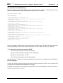
Note:
Some Intel flash chips (e.g. 28F800C3, 28F160C3, 28F320C3) power-up with all blocks in locked
state. In order to erase/program those flash chips, use the init list to unlock the appropriate blocks.
WM16
WM16
WM16
WM16
WM16
0xFFF00000
0xFFF00000
0xFFF10000
0xFFF10000
....
0xFFF00000
0x0060
0x00D0
0x0060
0x00D0
unlock block 0
0xFFFF
select read mode
unlock block 1
Not all flash chips support a chip erase command. Also if a chip erase takes too long, the BDI communication layer may time-out. In this case, use multiple sector erase commands
© Copyright 1992-2005 by ABATRON AG
V 1.00
bdiNDI
BDM interface for Nucleus™ Debugger, BDI2000 (ColdFire)
User Manual
28
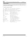
6 Telnet Interface
A Telnet server is integrated within the BDI that can be accessed when the BDI is connected via ethernet to the host. It may help to invertigate problems and allows access to target resources that can
not directly be accessed by the debugger.
The following commands are available:
"MD
[<address>] [<count>]
"MDH
[<address>] [<count>]
"MDB
[<address>] [<count>]
"DUMP <addr> <size> [<file>]
"MM
<addr> <value> [<cnt>]
"MMH
<addr> <value> [<cnt>]
"MMB
<addr> <value> [<cnt>]
"RD
"RDC
<nbr>
"RDFP
"RM
<nbr> <value>
"RMC
<nbr> <value>
"TLB
<from> [<to>]
"WTLB <idx> <epn> <rpn>
"BOOT
"RESET
"GO
[<pc>]
"TI
[<pc>]
"HALT
"BI <addr>
"CI [<id>]
"BD [R|W] <addr>
"BDH [R|W] <addr>
"BDB [R|W] <addr>
"CD [<id>]
"INFO
"DCMD <direct command>
"HELP
"QUIT
display target memory as word (32bit)",
display target memory as half word (16bit)",
display target memory as byte (8bit)",
dump target memory to a file",
modify word(s) (32bit) in target memory",
modify half word(s) (16bit) in target memory",
modify byte(s) (8bit) in target memory",
display CPU register",
display a control register",
display floating point registers",
modify data/address register",
modify a control register",
display TLB entry (only V4e cores)",
write TLB entry (only V4e cores)",
reset the BDI",
reset the target system",
set PC and start target system",
single step an instruction",
force target to enter debug mode",
set instruction hardware breakpoint",
clear instruction hardware breakpoint(s)",
set data watchpoint (32bit access)",
set data watchpoint (16bit access)",
set data watchpoint ( 8bit access)",
clear data breakpoint(s)",
display information about the current state",
execute a BDI direct command (see manual)",
display command list",
terminate the Telnet session"
© Copyright 1992-2005 by ABATRON AG
V 1.00
bdiNDI
BDM interface for Nucleus™ Debugger, BDI2000 (ColdFire)
User Manual
29
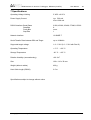
7 Specifications
Operating Voltage Limiting
5 VDC ± 0.25 V
Power Supply Current
typ. 500 mA
max. 1000 mA
RS232 Interface: Baud Rates
Data Bits
Parity Bits
Stop Bits
9’600,19’200, 38’400, 57’600,115’200
8
none
1
Network Interface
10 BASE-T
Serial Transfer Rate between BDI and Target
up to 16 Mbit/s
Supported target voltage
1.8 – 5.0 V (3.0 – 5.0 V with Rev. B)
Operating Temperature
+ 5 °C ... +60 °C
Storage Temperature
-20 °C ... +65 °C
Relative Humidity (noncondensing)
<90 %rF
Size
190 x 110 x 35 mm
Weight (without cables)
420 g
Host Cable length (RS232)
2.5 m
Specifications subject to change without notice
© Copyright 1992-2005 by ABATRON AG
V 1.00
bdiNDI
BDM interface for Nucleus™ Debugger, BDI2000 (ColdFire)
User Manual
30
8 Warranty
ABATRON Switzerland warrants the physical diskette, cable, BDI2000 and physical documentation
to be free of defects in materials and workmanship for a period of 24 months following the date of
purchase when used under normal conditions.
In the event of notification within the warranty period of defects in material or workmanship,
ABATRON will replace defective diskette, cable, BDI2000 or documentation. The remedy for breach
of this warranty shall be limited to replacement and shall not encompass any other damages, including but not limited loss of profit, special, incidental, consequential, or other similar claims.
ABATRON Switzerland specifically disclaims all other warranties- expressed or implied, including but
not limited to implied warranties of merchantability and fitness for particular purposes - with respect
to defects in the diskette, cable, BDI2000 and documentation, and the program license granted herein, including without limitation the operation of the program with respect to any particular application,
use, or purposes. In no event shall ABATRON be liable for any loss of profit or any other commercial
damage, including but not limited to special, incidental, consequential, or other damages.
Failure in handling which leads to defects are not covered under this warranty. The warranty is void
under any self-made repair operation except exchanging the fuse.
© Copyright 1992-2005 by ABATRON AG
V 1.00
bdiNDI
BDM interface for Nucleus™ Debugger, BDI2000 (ColdFire)
User Manual
31
Appendices
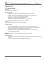
A Troubleshooting
Problem
The firmware can not be loaded.
Possible reasons
• The BDI is not correctly connected with the target system (see chapter 2).
• The power supply of the target system is switched off or not in operating range
(4.75 VDC ... 5.25 VDC) --> MODE LED is OFF or RED
• The built in fuse is damaged --> MODE LED is OFF
• The BDI is not correctly connected with the Host (see chapter 2).
• A wrong communication port (Com 1...Com 4) is selected.
Problem
No working with the target system (loading firmware is ok).
Possible reasons
• Wrong pin assignment (BDM/JTAG connector) of the target system (see chapter 2).
• Target system initialization is not correctly --> enter an appropriate target initialization list.
• An incorrect IP address was entered (BDI2000 configuration)
• BDM/JTAG signals from the target system are not correctly (short-circuit, break, ...).
• The target system is damaged.
Problem
Network processes do not function (loading the firmware was successful)
Possible reasons
• The BDI2000 is not connected or not correctly connected to the network (LAN cable or media
converter)
• An incorrect IP address was entered (BDI2000 configuration)
© Copyright 1992-2005 by ABATRON AG
V 1.00
bdiNDI
BDM interface for Nucleus™ Debugger, BDI2000 (ColdFire)
User Manual
32
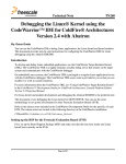
B Maintenance
The BDI needs no special maintenance. Clean the housing with a mild detergent only. Solvents such
as gasoline may damage it.
If the BDI is connected correctly and it is still not responding, then the built in fuse might be damaged
(in cases where the device was used with wrong supply voltage or wrong polarity). To exchange the
fuse or to perform special initialization, please proceed according to the following steps:
!
Observe precautions for handling (Electrostatic sensitive device)
Unplug the cables before opening the cover.
Use exact fuse replacement (Microfuse MSF 1.6 AF).
Swiss Made
1.1 Unplug the cables
2
2.1 Remove the two plastic caps that cover the screws on target front side
(e.g. with a small knife)
2.2 Remove the two screws that hold the front panel
BDI
3
Abatron AG
BDI2000
1
TRGT MODE
BDI MAIN
BDI OPTION
3.1 While holding the casing, remove the front panel and the red elastig sealing
casing
elastic sealing
front panel
© Copyright 1992-2005 by ABATRON AG
V 1.00
bdiNDI
4
BDM interface for Nucleus™ Debugger, BDI2000 (ColdFire)
User Manual
33
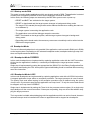
4.1 While holding the casing, slide carefully the print in position as shown in
figure below
Jumper settings
DEFAULT
INIT MODE
Fuse Position
Rev. B/C
Fuse Position
Rev. A
Pull-out carefully the fuse and replace it
Type: Microfuse MSF 1.6AF
Manufacturer: Schurter
5
Reinstallation
5.1 Slide back carefully the print. Check that the LEDs align with the holes in the
back panel.
5.2 Push carefully the front panel and the red elastig sealing on the casing.
Check that the LEDs align with the holes in the front panel and that the
position of the sealing is as shown in the figure below.
casing
elastic sealing
back panel
front panel
5.3 Mount the screws (do not overtighten it)
5.4 Mount the two plastic caps that cover the screws
5.5 Plug the cables
!
Observe precautions for handling (Electrostatic sensitive device)
Unplug the cables before opening the cover.
Use exact fuse replacement (Microfuse MSF 1.6 AF).
© Copyright 1992-2005 by ABATRON AG
V 1.00
bdiNDI
BDM interface for Nucleus™ Debugger, BDI2000 (ColdFire)
User Manual
34
C Trademarks
All trademarks are property of their respective holders.
© Copyright 1992-2005 by ABATRON AG
V 1.00