1
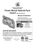
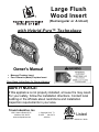
Large Flush
Wood Insert
(Rectangular or Arched)
with Hybrid-Fyre™ Technology
Owner's Manual
Masonry Fireplace Insert
Zero-Clearance (Metal) Fireplace Insert
Save these instructions for future reference
SAFETY NOTICE:
If this appliance is not properly installed, a house fire may result.
For your safety, follow the installation directions. Contact local
building or fire officials about restrictions and installation
inspection requirements in your area.
Travis Industries, Inc.
12521 Harbour Reach Drive
Mukilteo, WA 98275
www.travisproducts.com
Copyright 2015, T.I.
$10.00
100-01273
4150514
Listed
Tested to: U.L. 1482 & ULC S628
2
Introduction
Introduction
We welcome you as a new owner of a Large Flush Wood Insert. In purchasing a Large Flush Wood Insert
you have joined the growing ranks of concerned individuals whose selection of an energy system reflects
both a concern for the environment and aesthetics. This insert is one of the finest appliances the world
over. This manual will explain the installation, operation, and maintenance of this appliance. Please
familiarize yourself with the Owner's Manual before operating your appliance and save the manual for future
reference. Included are helpful hints and suggestions which will make the installation and operation of your
new appliance an easier and more enjoyable experience. We offer our continual support and guidance to
help you achieve the maximum benefit and enjoyment from your appliance.
Important Information
No other Large Flush Wood Insert appliance has the
same serial number as yours. The serial number is
stamped onto the label on the back of the appliance.
This serial number will be needed in case you require
service of any type.
Model:
Serial Number:
Purchase Date:
Purchased From:
© Travis Industries
Register your warranty online at:
traviswarranty.com
Or, mail your warranty card to:
Travis Industries House of Fire
12521 Harbour Reach Drive
Mukilteo, WA 98275
Large Flush Wood Insert_
Save Your Bill of Sale.
To receive full warranty coverage, you will
need to show evidence of the date you
purchased your heater. Do not mail your Bill
of Sale to us.
We suggest that you attach your Bill of Sale
to this page so that you will have all the
information you need in one place should the
need for service or information occur.
100-01273
4150514
Table of Contents
Introduction ...................................................... 2 Important Information ...................................... 2 Installation Options.......................................... 6 Features ............................................................ 6 Heating Specifications..................................... 6 Dimensions ....................................................... 6 Emissions and Efficiency ................................ 6 Planning the Installation.................................. 7 Preparation for Installation .................................... 7 Additional Accessories Needed for Installation ..... 7 Additional Requirements for Canada .................... 7 Fireplace Requirements .................................. 8 Fireplace Altered Tag....................................... 8 Insert Placement Requirements ..................... 9 Hearth Requirements ..................................... 10 USA .................................................................... 10 CANADA ............................................................. 10 Mantel Requirements ..................................... 10 Masonry Fireplace Requirements ................ 11 Zero-Clearance (Metal) Fireplace
Requirements ................................................. 11 Drafting Performance .................................... 12 Insert Rollers .................................................. 12 Leveling Bolt Installation............................... 12 Fettle Installation ............................................ 12 Flue Installation .............................................. 13 Inspecting & Cleaning the Combustor ................. 19 Starting a Fire ................................................. 20 Adjusting the Burn Rate ................................ 21 Approximate Air Control Settings: ....................... 21 Ash Removal .................................................. 21 Understanding Your Heater’s Combustion
System ............................................................ 22 Burning Your Heater ...................................... 22 Blower Operation ........................................... 23 Re-Loading the Stove .................................... 23 Overnight Burn............................................... 23 Normal Operating Sounds ............................ 23 Hints for Burning ........................................... 24 Selecting Wood .............................................. 24 Why Dry Wood is Key ......................................... 24 Wood Cutting and Storage .................................. 24 Do Not Burn List.................................................. 25 Troubleshooting............................................. 26 Daily Maintenance (while stove is in use) ... 27 Clean the Glass (if necessary) ............................ 27 Monthly Maintenance (while appliance is in
use) .................................................................. 28 Door and Glass Inspection .................................. 28 Door Latch Adjustment ....................................... 28 Creosote - Formation and Need for Removal ..... 28 Yearly Maintenance ....................................... 29 Touch-Up Paint ................................................... 29 Cleaning the Air Duct and Blower (if applicable) . 29 Firebrick and Baffle Inspection ............................ 29 Cleaning the Catalytic Combustor....................... 30 Sealing the Flue to the Insert .............................. 13 Surround Panel Installation .......................... 14 Face Installation ............................................. 14 Re-Routing the Electrical Cord to the Left
Side .................................................................. 15 Safety Notice .................................................. 16 Before Your First Fire .................................... 16 Verify the Installation ........................................... 16 Curing the Paint .................................................. 16 Carbon Monoxide (CO) Emissions ...................... 16 Over-Firing the Stove .......................................... 16 Opening the Door ........................................... 17 Opening the Door ................................................ 17 Closing the Door ................................................. 17 Bypass Operation .......................................... 18 Maintaining Catalytic Burn-Off ..................... 18 Catalytic Combustor – Use and Cleaning.... 19 © Travis Industries
3
Door Parts....................................................... 31 Replacing the Glass ............................................ 31 Replacing the Door Gasket ................................. 31 Blower and Electrical Parts .......................... 32 Firebox Parts .................................................. 33 Baffle Parts ......................................................... 33 Baffle Removal.................................................... 33 Combustor .......................................................... 33 Air Tube Removal & Replacement ............... 34 Brick Removal & Replacement ........................... 35 GreenStartTM Igniter – Firebrick and Housing
Installation ...................................................... 36 100-01273
Listing Label ........................................................ 40 4150514
4
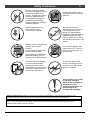
Safety Precautions
The viewing door must be
closed and latched during
operation.
Smoke from this appliance may
active a smoke detector when
the door is open.
Never block free airflow through
the air vents on this appliance.
Gas
This appliance is designed and
approved for the burning of cord
wood only. Do not attempt to
burn any other type of fuel other
than cord wood in this
appliance, it will void all
warranties and safety listings.
Do not touch the appliance while
it is hot and educate all children
of the danger of a hightemperature appliance. Young
children should be supervised
when they are in the same room
as the appliance.
ASHES
Inspect the chimney connector
and chimney at least twice
monthly and clean if necessary.
Creosote may build up and
cause a house fire.
Do not connect this appliance to
any chimney serving another
appliance.
© Travis Industries
100-01273
Ok
Type
HT
Ashes must be disposed in a
metal container with a tight lid
and placed on a noncombustible surface well away
from the home or structure.
Keep furniture, drapes, curtains,
wood, paper, and other
combustibles a minimum of 36"
away from the front of the
appliance.
36"
This appliance must be properly
installed to prevent the
possibility of a house fire. The
instructions must be strictly
adhered to. Do not use
makeshift methods or
compromise in the installation.
Gasoline or other flammable
liquids must never be used to
start the fire or "Freshen Up" the
fire. Do not store or use
gasoline or other flammable
liquids in the vicinity of this
appliance.
Clay
Liner
Contact your local building
officials to obtain a permit and
information on any installation
restrictions or inspection
requirements in your area.
Notify your insurance company
of this appliance as well.
This appliance must be
connected to a listed high
temperature (UL 103 HT)
residential type chimney or an
approved masonry chimney with
a standard clay tile, or stainless
steel liner.
4150514
Safety Precautions
Never try to repair or replace
any part of this appliance unless
instructions are given in this
manual. All other work must be
done by a trained technician.
Do not make any changes or
modifications to an existing
masonry fireplace or chimney to
install this appliance.
Allow the appliance to cool
before carrying out any
maintenance or cleaning.
Maintain the door and glass seal
and keep them in good
condition.
Do not operate this heater with
broken or missing glass.
Avoid placing wood against the
glass when loading. Do not
slam the door or strike the glass.
This
Manual
Do not throw this manual away.
This manual has important
operating and maintenance
instructions that you will need at
a later time. Always follow the
instructions in this manual.
5
Do not place clothing or other
flammable items on or near this
appliance.
This wood heater has a
manufacturer-set minimum low
burn rate that must not be
altered. It is against federal
regulations to alter this setting or
otherwise operate this wood
heater in a manner inconsistent
with operating instructions in this
manual.
Over-firing the appliance may
cause a house fire. If a unit or
chimney connector glows, you
are over-firing.
Do not use a grate or other
device to elevate the fire off of
the firebox floor. Burn the fire
directly on the bricks.
Travis Industries, Inc. grants
no warranty, implied or
stated, for the installation or
maintenance of your
appliance, and assumes no
responsibility of any
consequential damage(s).
Smoke and CO Detectors: Make sure your home has a working smoke detector, especially near any bedrooms. We
recommend having a smoke and/or CO detector in the same room as the wood heater for additional safety.
Proposition 65 Warning: Fuels used in gas, woodburning or oil fired appliances, and the products of combustion of such
fuels, contain chemicals known to the State of California to cause cancer, birth defects and other reproductive harm.
California Health & Safety Code Sec. 25249.6
© Travis Industries
100-01273
4150514
6
Stove Installation (for qualified installers only)
Installation Options
Features
Masonry Fireplace Insert
3 Cubic Foot Firebox Volume
Zero-Clearance (Metal) Fireplace Insert
Single Air Control
Accepts Logs Up to 24" Long
Steel Plate Construction (Up to 5/16")
Heavy Duty Refractory Firebrick
Standard High-Tech Blower
Heating Specifications
Approximate Maximum Heating Capacity (in square feet)*
1,500 to 2,500
Maximum Burn Time
Up to 12 Hours
* Heating capacity will vary depending on the home's floor plan, degree of insulation, and the outside
temperature. It is also affected by the quality and moisture level of the fuel.
This model was tested for efficiency using method B415.1-10 and was determined to have a weighted average
Higher Heating Value (HHV) Overall Heating Efficiency (OHE) of 80.3%.
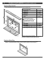
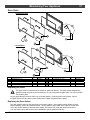
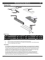
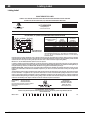
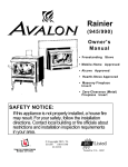
Dimensions
6" (153mm) Dia.
530 Lbs. (236 Kg)
31" 788mm
6.25"
159 mm
20.75"
528mm
22"
559mm
23.5"
597mm
a
9.75"
248mm
19"
483mm
b
(a) Measure clearances from base of insert
Figure 1
(b) Fireplace Opening
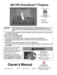
Emissions and Efficiency
This heater meets the 2015 U.S. EPA’s crib wood emission limits for wood heaters sold after May 15,
2015. Tested to Method 28, 5G2 this heater has been shown to deliver heat at rates ranging from 8,500
to 35,300 BTU/hr and an emission value of 0.58 g/h.
© Travis Industries
100-01273
4150514
Fireplace Insert Installation (for qualified installers only)
7
SAFETY NOTICE:
Please read this entire manual before you install and use your new room heater. Failure to
follow instructions may result in property damage, bodily injury, or even death. Contact
local building or fire officials about restrictions and installation inspection requirements in
your area.
Planning the Installation
We suggest that you have an authorized Travis Industries dealer install your fireplace insert. If you
install the fireplace insert yourself, your authorized dealer should review your installation plans.
Check with local building officials for any permits required for installation of this fireplace insert and
notify your insurance company before proceeding with installation.
The location of your wood heater in your home will decide how affectively the heat produced will spread
throughout your house. Attention to the home design with consideration of natural convection and air
circulation should be taken into account when choosing the placement of your heater within the home.
Preparation for Installation
Check for damage to the exterior of the fireplace insert (dents should be reported, scratches can be
fixed by applying touch-up paint).
Check the interior of the firebox (replace cracked firebrick and make sure baffle is in place).
The fireplace insert can be lightened by removing the firebricks and baffle (pg. 35) - replace before
operation.
Additional Accessories Needed for Installation
Face
Surround Panels (see page14)
Additional Requirements for Canada
Do not remove bricks or mortar from existing fireplace.
This fireplace insert must be installed with a continuous chimney liner of 6” diameter extending from
the fireplace insert to the top of the chimney. The chimney liner must conform to the Class 3
requirements of CAN/ULC-S635, Standard for Lining Systems for Existing Masonry or Factory-Built
Chimneys and Vents, or CAN/ULC-S640, Standard for Lining Systems for New Masonry Chimneys.
Permanently seal any opening between the masonry of the fireplace and the facing masonry.
Fireplace insert, or surround panels, may be removed to inspect fireplace insert and fireplace.
Lock existing dampers in the open position.
© Travis Industries
100-01273
4150514
8
Fireplace Insert Installation (for qualified installers only)
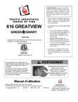
Fireplace Requirements
Figure 2 shows the minimum size requirements for the type of fireplace used.
Minimum Fireplace Size
Co
mb
us
tib
le
Ma
nte
l
j
No
n-C
om
i
h
bu
stib
le
b
Fa
cin
g
a
d
No
c
n-C
om
bu
g
stib
le
He
e
art
a
Height (front)
23.5" 597mm
b
Height (rear)
22" 559mm
c
Width (front)
33”* 839mm*
d
Width (rear)
20.75” 528mm
e
Depth
19” 483mm
f Hearth Depth
NOTE: Base of insert must be a
minimum 1” above combustible floor
surfaces (carpet, wood, etc.). See
“Hearth Requirements” for further
details.
18”** 458mm**
g
Hearth Width
47" 1093mm
h
Facing Width
42" 1194mm
i
Facing Height Above Base of Insert
37" 940mm
j
Mantel Height Above Base of Insert
41" 1042mm
h
f
Figure 2
* Includes 2” (51mm) for power cord installation.
** In the US, a 16” (407mm) hearth may be used if base of insert is 2”
(51mm) above combustible floor surfaces (carpet, wood, etc.).
Fireplace Altered Tag
Attach the "This fireplace has been altered..." plate to the fireplace (use two screws or other suitable
method). You may wish to place it in a location where it will be covered by the surround panels.
© Travis Industries
100-01273
4150514
Fireplace Insert Installation (for qualified installers only)
9
Insert Placement Requirements
The insert must be placed so that no combustibles are within, or can swing within (e.g. drapes,
doors), 36" (915mm) of the front of the insert ( Figure 3 “q”).
Insert and hearth must be installed on a level, secure floor
The minimum clearances, facing, and hearth requirements in Figure 3 must be met.
Minimum Clearances
k Sidewall
10.5" 267mm
l Side Facing (non-combustible)
5.5" 140mm
m Top Facing (non-combustible)
37" 940mm
n Mantel (combustible)
41" 1042mm
o Front Hearth
NOTE: Base of insert must be a minimum 1” above
combustible floor surfaces (carpet, wood, etc.). See
“Hearth Requirements” for further details.
18”* 458mm*
p Side Hearth
8" 204mm
q Front of Insert
36" 915mm
r Mantel Breastplate (max. 1” 26mm thick)
37” 940mm
s Mantel Column (max. 8” 204mm deep)
5.5" 140mm
x Extension Onto Hearth (from front edge of insert)
0" 0mm
* In the US, a 16” (407mm) hearth may be used if base of insert is 2” (51mm) above combustible floor
surfaces (carpet, wood, etc.). See “Hearth Requirements” for full details.
Co
mb
us
tib
le
Ma
nte
l
Fa
cin
Side
Wall
Co
g
mb
us
k
n
r
tib
le
To
pF
ac
ing
Max. 1"
26mm
m
s
p
x
l
No
n-C
q
o
He mbus
art
h tible
o
Figure 3
© Travis Industries
100-01273
4150514
10
Fireplace Insert Installation (for qualified installers only)
Hearth Requirements
When installing into a masonry fireplace, the hearth must meet Uniform Building Code (UBC) standards.
A UBC hearth extending 16” (407mm) in front of the fireplace insert must have a surface 2” (51mm)
above the surrounding combustible floor. (Canada) A UBC hearth extending 18” (458mm) in front of the
fireplace insert must have a surface 1” (25mm) above the surrounding combustible floor. The surface of a
UBC hearth may be raised by applying any noncombustible material. A hearth extending 20” (508mm) or
more has no height requirement.
USA
When installing into a zero-clearance fireplace, the hearth must extend 16” (407mm) to the front and 8”
(204mm) to the sides of the insert. The surface of the hearth must be 2” (51mm) above the surrounding
combustible floor and the hearth must provide and R-value (thermal resistance) of 2.38 or greater.
If the insert is a minimum 7” (178mm) above the combustible floor (carpet, wood, etc.) the hearth must
extend 16” (407mm) in front and 8” (204mm) on both sides of the insert. Hearth must be non-combustible
(cement board, tile, etc.). No R-value (thermal resistance) is required.
CANADA
When installing into a zero-clearance fireplace, the hearth must extend 18” (458mm) to the front and 8”
(204mm) to the sides of the insert. The surface of the hearth must be 1” (25mm) above the surrounding
combustible floor and the hearth must provide and R-value (thermal resistance) of 2.38 or greater.
If the insert is a minimum 7” (178mm) above the combustible floor (carpet, wood, etc.) the hearth must
extend 18” (458mm) in front and 8” (204mm) on both sides of the insert. Hearth must be non-combustible
(cement board, tile, etc.). No R-value (thermal resistance) is required.
Non-Combustible Hearth
(Tile, Cement Board, etc.)
Non-Combustible Hearth
(min. R-Value 2.38)
Min. 7”
(178mm)
Min. 1” (25mm)
Combustible
Flooring
Min. 18” (458mm)
Combustible
Flooring
USA Min. 16” (407mm)
Canada Min. 18” (458mm)
Mantel Requirements
See minimum mantel clearances below.
Max. 12" (305mm)
Max. 1" (25mm)
Min. 41"
(1042mm)
Min. 37"
(940mm)
Mantel Height
Above Base of Fireplace
0"
1"
(25
2" mm
)
(5
3" 1mm
(7
)
4" 6mm
(10
)
5" 2m
m)
(1
6" 27m
(15 m)
2
7"
mm
(1
)
8" 78m
(20 m)
9" 3m
m)
(2
10 29mm
" (2
)
11 54m
m)
" (2
12 79
" (3 mm
05 )
mm
)
Maximum Mantel Depth (b)
41" (1042mm)
40"
39"
38"
Base of Insert
© Travis Industries
37" (940mm)
100-01273
4150514
Fireplace Insert Installation (for qualified installers only)
11
Masonry Fireplace Requirements
Must utilize a positive connection (full reline)
Entire fireplace, including chimney, must be clean and undamaged. Any damage must be repaired
prior to installation of the insert.
Chimney height: 15' (4.5M) minimum; 33' (10M) maximum (measured from base of insert).
Entire fireplace, including chimney, must meet local building requirements.
The fireplace insert must be placed on a masonry hearth built to UBC standards.
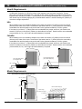
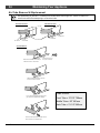
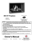
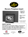
Zero-Clearance (Metal) Fireplace Requirements
Must be manufactured by one of the following manufacturers:
• Marco • Majestic • Heatilator • Preway • Tempco • Superior
• Heat N Glo • Lennox • Martin • Monesson
Entire fireplace, including chimney, must meet local building requirements
Chimney height: 15' minimum; 33' maximum.
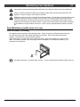
The damper ("A") and grate ("B") must be removed (see illustration below). The smoke shelf ("C"),
internal baffles ("D"), screen ("E"), and metal or glass doors ("F") may be removed (if applicable).
The masonry lining ("G"), insulation ("H"), and any structured rigid frame members (metal sides, floor,
door frame, face of the fireplace, etc. – "I") may not be removed or altered
H
A
C
F
D
I
E
B
G
The chimney on the ZC fireplace must be listed per UL 127 or ULC 610-M87 for all installations. Any
thermal protection component of the fireplace or chimney must remain in place. The fireplace and
chimney must be inspected prior to installation. A NFPA 211 Level II inspection is recommended.
Repairs must be made prior to insert installation. The base of the fireplace must be structurally sound
and able to support the weight of the insert.
The stainless steel liner must be 6” diameter and extend the full height of the chimney (also called a
positive connection or full re-line). This liner must meet type HT (2100°F) requirements per UL 1777
(USA) or ULC S635 with “0” clearance to masonry (Canada). The liner must be attached to the insert
flue collar and to the top of the existing chimney.
We recommend using the listed Travis ZC Liner Kit from Duravent (SKU 98900046, 47, or 48). If you
do not use this kit, you must use the original ZC chimney cap.
The liner support and cap at the top of the chimney must not reduce air flow for the existing air-cooled
chimney system. The Travis ZC Liner Kit includes a cap that meets this provision.
To prevent air from passing up the ZC fireplace chimney (the gap between the liner and chimney) we
recommend sealing the area near the damper. Use non-combustible material to seal this area (nonbacked fiberglass insulation or kaowool).
The convection air channel on the fireplace must not be blocked. Do not block any louvers, grills, or
air passages on the front of the fireplace.
Entire fireplace, including chimney, must meet local building requirements. Permits may be required
for installation. Final approval is contingent upon the authority having local jurisdiction. Inform you
insurance agent of this fireplace insert.
© Travis Industries
100-01273
4150514
12
Fireplace Insert Installation (for qualified installers only)
Drafting Performance
Draft is the force which moves air from the appliance up through the chimney. The amount of draft in your
chimney depends on the length of the chimney, local geography, nearby obstructions and other factors.
Too much draft may cause excessive temperatures in the appliance and may damage the heater.
Inadequate draft may cause backpuffing into the room and `plugging' of the chimney. Inadequate draft
will cause the appliance to leak smoke into the room through appliance and chimney connector joints. An
uncontrollable burn or excessive temperature indicates excessive draft.
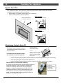
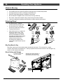
Insert Rollers
Two rollers are built into the back edge of the insert. This
allows the insert to be rolled into position by lifting the front
of the insert and pushing it into position (see Figure 4).
Figure 4
Leveling Bolt Installation
MASONRY NOTE: Place a metal plate below the
bolts on masonry fireplaces to prevent damage to the
floor brick.
Two leveling bolts are pre-installed on the insert to
allow for proper leveling within the fireplace. To
access the bolts, remove the back corner firebricks
and cover plates “a” and “b”). The bolts are prethreaded to a weld-nut on the base of the insert. Use
a 3/4” socket wrench to screw the bolts down
(clockwise) until the insert is level (see “c”).
b
a
c
SEALING THE COVER PLATE: We recommend
sealing the cover plate with furnace cement (place on
underside of cover plate).
BOLT LENGTH: The included bolts allow
approximately 1” of rise. If additional rise is required,
use a longer 1/2-13 thread bolt. Make sure the
additional bolt length does not interfere with the cover
plate.
Figure 5
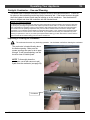
Fettle Installation
The fettle is designed to prevent ash from spilling out of the firebox opening. It is held in place with two tabs
and slots at the front of the firebox (see pictures below). The fettle is optional and may be removed if desired.
© Travis Industries
100-01273
4150514
Fireplace Insert Installation (for qualified installers only)
13
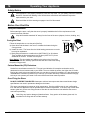
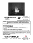
Flue Installation
RLH Chim-Flex Starter Sections
Flue (flexible or rigid)
Included in the owner’s pack are
three “flue brackets” and six selfdrilling screws. Use these
Flue Bracket
components to secure the flue to the
fireplace insert.
Self-Drilling Screws
RLH manufactures starter
sections in straight or
angled configurations to
suit your application.
They are secured from
inside the firebox, making
installation much easier.
Contact RLH for additional
details:
Flue Opening
www.chim-flex.com
Sealing the Flue to the Insert
This insert utilizes a catalytic combustor to increase efficiency and decrease emissions. This increases
the air resistance inside the firebox, making the flue connection especially important. To insure proper
draft, and to prevent smoke spillage during re-loading, it is crucial for the flue to be sealed with
fireplace cement. If an adapter is used, both joints to the liner and to the insert must be sealed. Use a
generous amount of fireplace cement at every connection (where the flue connects to the insert and at
every joint).
In addition, we recommend using non-combustible fiberglass insulation to seal the fireplace enclosure.
By sealing the top and bottom of the chimney, and the surround panels, you will be ensuring outside air is
not pulled into the chimney.
Install a non-combustible
cover plate to prevent water
from entering the chimney
Cap (prevents water from
entering)
Flue Liner
The liner must be stainless
steel connector or flexible vent.
Follow the liner manufacturer's
insturctions for installation and
support.
Combustible Mantle
Airtight Insulated
Clean-Out
Remove damper or wire it open
See the section "Insert
Placement Requirements" for
minimum clearances and
hearth required.
ce
rna ent
u
F m
Ce
We recommend using non-combustible
fiberglass insulation to seal the fireplace
enclosure (chimney top and bottom, and
surround panels)
Seal the flue connection to the insert
© Travis Industries
100-01273
4150514
14
Fireplace Insert Installation (for qualified installers only)
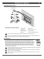
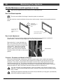
Surround Panel Installation
Standard Size
Width
Height
Part#
42"
32-1/2"
96100392
1. Before installing, the insert should be in place with the flue attached. Attach the brackets as
shown below, using the screws included in the hardware pack with the insert. Make sure the
brackets are flush with the front of the convection chamber.
2. Attach the surround panel as shown below.
NOTE: When installing the panel, route the power cord and rheostat wires through the notch on the bottom of
the panel (right side). Route the catalytic temperature probe wire through the notch on the left side.
Make sure these wires do not become pinched or damaged during panel and face installation.
Face Installation
There are several face options available for this fireplace insert. Refer to the instructions included with
your face.
© Travis Industries
100-01273
4150514
Fireplace Insert Installation (for qualified installers only)
15
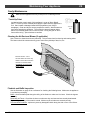
Re-Routing the Electrical Cord to the Left Side
The power cord is connected to the right side of the insert when it leaves the factory. It may be re-routed
to the left side following the directions below. Do this procedure before installing the surround panels.
Disconnect the Molex connector and remove the power cord following the directions below.
Disconnect the molex connector
leading from the power cord.
Rheostat Wires
Power
Cord
Use pliers to compress the strain relief
from the top and bottom while pulling it
out of the hole in the side of the insert.
NOTE: An additional knockout is
provided if using the insert wiring kit.
Route the power through one hole,
the rheostat through the other.
Leave the rheostat
wires in place.
Make sure the power cord is
disconnected prior to
conducting these steps.
Remove the power cord.
Connect the power cord to the left side following the directions below.
Attach the molex connector on the
power cord to the molex connector
on the left side of the insert.
Power
Cord
Re-attach the strain relief to the left side (use
pliers to compress the strain relief from the top
and bottom while pushing it into the hole).
Remove the button plug from the left side.
© Travis Industries
100-01273
4150514
16
Operating Your Appliance
Safety Notice
If this appliance is not properly installed, a house fire may result. For your safety, follow the installation
directions. Contact local building or fire officials about restrictions and installation inspection
requirements in your area.
Read and follow all of the warnings on pages 4 and 5 of this manual.
Before Your First Fire
Verify the Installation
Before starting the stove, verify that the stove is properly installed and all of the requirements in this
manual have been followed.
Keep all flammable materials 36" away from the front of the stove (drapes, furniture, clothing, etc.).
Curing the Paint
2 to 4 hours
Follow the steps below to cure the paint (first fire):
a) Open doors and windows in the room to ventilate the heater during the
curing process.
b) Vacate the room. The fumes from the initial heating process are non-toxic
but may be unpleasant.
c) Slowly bring the heater to a medium burn (400°F/204°C) for 45 minutes.
Then increase the burn temperature to a hot burn (600°F/315°C) for an
additional 45 minutes. This will cure the paint.
Door Gasket - The door gasket can adhere to the paint on the front of the
heater. To prevent this, carefully open and close the door a few times during
the paint curing process.
Carbon Monoxide (CO) Emissions
Smoke from wood heaters contain CO. This gas is an indication of incomplete combustion and is
detrimental to the environment and to your health. The more visible the smoke, the higher the CO levels.
Burning dry wood is the most significant step you can take to reduce CO emissions. It is also important to
understand the combustion process so you can burn your heater efficiently. Read the manual thoroughly
so that you can operate your heater in the most efficient and clean manner possible.
Over-Firing the Stove
DO NOT OVERFIRE THIS HEATER: Attempts to achieve heat output rates that exceed heater design
specifications can result in permanent damage to the heater.
This stove was designed to operate at a high temperature. But due to differences in vent configuration,
fuel, and draft, this appliance can be operated at an excessive temperature. If the stove top or other area
starts to glow red, you are over-firing the stove. Shut the air control down to low and allow the stove to
cool before proceeding.
Over-firing may lead to damage of plated surfaces. If any portion of the heater glows red, it is
considered over-firing and will void the warranty.
© Travis Industries
100-01273
4150514
Operating Your Appliance
17
Opening the Door
The door becomes hot during use. Use a glove to open the door if the handle is hot.
To prevent smoke from entering the room, open the bypass before opening the door (see following page
for directions). You can also open the door a small amount and let air enter the firebox.
Opening the Door
Closing the Door
© Travis Industries
100-01273
4150514
18
Operating Your Appliance
Bypass Operation
The bypass controls the flow of smoke inside the heater. When pulled out, smoke goes directly up the
flue, creating more draft. When pushed in, the smoke goes around the baffle, utilizing the secondary
combustion and making the heater more efficient.
When starting or re-loading, pull the bypass out, if necessary.
During normal operation, push the bypass in.
Use the included pull tool
to operate the bypass rod
Bypass Pulled Out
Used for starting and re-loading
Bypass Pushed In
Used for normal operation
Maintaining Catalytic Burn-Off
This fireplace uses a catalytic combustor
to increase heat transfer to the room and
reduce emissions.
Follow the directions below to utilize
the combustor to its fullest potential.
•
•
•
The catalytic combustor
takes dirty smoke and turns it
into extra heat and cleaner
emissions.
NOTE: If the combustor is engaged
(bypass closed) when the fireplace
is still cool, it will not work, leading
to dirty smoke, no extra heat, and a
dirtier combustor.
Keep the by-pass open (pulled out) until the fireplace becomes hot (approximately 15 to 30 minutes).
Close the by-pass (push in) when the fireplace is hot.
Keep the by-pass closed (pushed in) while the fireplace is operating, except when re-loading.
How to Check if your Combustor is Working
A combustor temperature probe is included with the fireplace to
monitor the combustor. After the bypass is engaged, the
combustor temperature should rise, showing combustor
operation. Combustor temperatures over 500° F (260° C),
indicate the combustor is working and igniting unburnt fuel.
The combustor can also be viewed through the glass from
below. You will notice the combustor glowing red when the
combustor is working effectively.
© Travis Industries
100-01273
Press this
ON/HOLD button
to view the
temperature
4150514
Operating Your Appliance
19
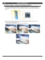
Catalytic Combustor – Use and Cleaning
This heater uses a catalytic combustor to improve efficiency and reduce emissions. To work at
its optimum, the combustor must be kept free of excessive ash. If the heater becomes sluggish
when the bypass is closed, flyash may be building up on the combustor. See the directions
below to inspect and clean the combustor with the included brush.
Testing your Catalyst Combustor
A combustor that is not functioning may still show active temperatures during the medium and high burn rates with
the primary fire providing enough heat to hold output temperatures above 500°f. To check the combustor function
burn your fireplace for at least 2-3 hours on the medium to high setting ensuring a full coal bed covers the firebox
floor and the unit is at operating temperature. Set your burn rate to medium low and monitor the catalyst output
temperature. The combustor should maintain a temperature above 500°f. If your combustor temp falls below 500°f
perform this test two or three times to ensure the results. If your results are the same your combustor may need
cleaning or replacement. Note: If you reload your fireplace before starting your burn test burn the new fuel load on
high for at least 20 min before setting your burn rate to medium low.
Inspecting & Cleaning the Combustor
The combustor becomes very hot during operation. Let the heater cool before cleaning the combustor.
The combustor is located directly above
the firebox opening. Make sure the
square openings are open for air to pass
through. If ash is accumulating, use the
brush to clear off visible flyash.
NOTE: To thoroughly clean the
combustor, use an ash vacuum to pull
flyash from the combustor (see page 30).
Combustor
© Travis Industries
100-01273
4150514
20
Operating Your Appliance
Starting a Fire
Since the dawn of time man has debated the best way to start a fire. Some use the boy-scout "tee-pee";
some prefer the "tic-tac-toe" stack. Either way, review the hints and warnings below to ensure proper fire
starting.
Make sure the air control is pushed in and the by-pass pulled out. If additional air is needed, open
the doors 1/4" during the first five minutes of start-up.
Never use gasoline, gasoline-type lantern fuel, kerosene, charcoal lighter fluid, or similar liquids to start
or "freshen up" a fire in this stove. Keep all such liquids well away from the stove while it is in use.
DO NOT USE CHEMICALS OR FLUIDS TO START THE FIRE. DO NOT BURN GARBAGE OR
FLAMMABLE FLUIDS SUCH AS GASOLINE, NAPHTHA OR ENGINE OIL. Do not place such fuel
within space heater installation clearances or within the space required for charging and ash removal.
If using a fire-starter, use only products specifically designed for stoves - follow the manufacturer's
instructions carefully.
HOT WHILE IN OPERATION. KEEP CHILDREN, CLOTHING AND FURNITURE AWAY. CONTACT
MAY CAUSE SKIN BURNS.
If the smoke does not pass up the chimney, ball up one sheet of newspaper, place it in the center of the
firebox and light it. This should start the chimney drafting (this eliminates "cold air blockage").
Use plenty of kindling to ensure the stove reaches a proper temperature. Once the kindling is burning
rapidly, place a few larger pieces of wood onto the fire.
Starting a “Top-Down Fire”
One particularly successful method for starting a fire is to
stack several large pieces of wood in the center of the stove
(see the illustration to the right). Then place a several wads
of newspaper in the center with kindling on top. When you
light the newspaper this “top-down” fire will burn its way to
the center, igniting the larger pieces. With some practice,
this method should work for you.
© Travis Industries
100-01273
4150514
Operating Your Appliance
21
Adjusting the Burn Rate
Use the air control slider to control the burn rate of the stove. See the illustration below for details.
Use the air control to
change the burn rate.
Low Burn
High Burn
(air control closed)
(air control open)
Approximate Air Control Settings:
Overnight Burn
Pulled fully out
Medium Burn
Pulled fully out to 1/16" In
Medium High Burn
1/16" to 11/64" In
High Burn
11/64" to Pushed All the Way In
The air control becomes hot during operation - use gloves or a tool to prevent burns.
The air control may take several minutes to influence the burn rate. When making adjustments, you
may wish to let the stove burn for 10 minutes to gauge performance.
Ash Removal
Whenever ashes get 3 to 4 inches deep in your firebox or ash pan, and when the fire has
burned down and cooled, remove excess ashes. Leave an ash bed approximately 1 inch
deep on the firebox bottom to help maintain a hot charcoal bed. Let the stove cool completely
before removing ashes (wait at least two hours after the last coal has extinguished). Ashes
should be placed in a metal container with a tight-fitting lid. The closed container of ashes
should be placed on a noncombustible floor or on the ground, away from all combustible
materials, pending final disposal. The ashes should be retained in the closed container until
all cinders have thoroughly cooled.
ASHES
Improperly disposed ashes lead to fires. Hot ashes placed in cardboard boxes, dumped in back yards,
or stored in garages, are recipes for disaster.
Wood-burning stoves are inherently dirty. During cleaning have a vacuum ready to catch spilled ash
(make sure ash is entirely extinguished).
There are vacuum cleaners specifically made to remove ash (even if the ash is warm). Contact your
dealer for details.
© Travis Industries
100-01273
4150514
22
Operating Your Appliance
Understanding Your Heater’s Combustion System
This heater uses a dual combustion system detailed below:
Primary Combustion: This is the combustion (fire) that takes place directly on the wood. Primary combustion
determines how fast the fire burns. Air for primary combustion is supplied through the air control. When you adjust
the air control you control the amount of air that reaches the fire and creates primary combustion. The air control
supplies air to the air wash (the air holes above the door opening – used to help clean the glass) and through the
pilot orifice (center bottom of the door opening). By using the air control, and supplying air through these two
openings, you control primary combustion.
Secondary & Catalytic Combustion: This is the combustion (fire) that does not contact the wood. Secondary
combustion burns the visible emissions or smoke that is not consumed during primary combustion. It takes place at
the top of the firebox and can appear as a glowing flame near the secondary air tubes. Catalytic combustion takes
place inside the catalytic combustor and is not viewable (you may, however, see the combustor glow). It also burns
the visible emissions or smoke that is not consumed during primary combustion. Catalytic combustion can be
monitored by using the included temperature meter. Your catalytic combustor is working when the output
temperature is above 500° F. (260°C).
Items to Consider:
During medium and high burn rates the stove will manage secondary and primary combustion on its own. When
the heater is set to a low burn rate more care is needed to ensure the secondary combustion system works
properly. Make sure the stove is hot and a good coal bed is established before adjusting your heater to low burn.
Understanding the combustion system in this heater will help minimize the visible emissions this heater releases
into the environment. The primary pilot orifice at the center bottom of the door opening is designed to help the
secondary combustion at low burn settings. The pilot provides a small amount of air that burns up through the fuel
load providing the heat and flame needed for the secondary system to ignite. The air tubes under the baffle need
to remain ignited for low burns to be effective.
As you load your heater for a low burn, take care in placing the wood. This will affect how well your secondary
system works as the wood is consumed. Do not block the pilot orifice. Stack wood so the pilot air can burn its
way up between the pieces, helping your heater burn effectively throughout the low fire. This will reduce the
visible emissions your heater produces and increase the amount of heat you get from the wood. If you are unsure
how well your heater is burning look at the chimney cap to monitor visible emissions.
Burning Your Heater
Starting a Fire: When starting a fire it is imperative to get the heater hot and drafting as quickly as possible. This
promotes combustion and reduces emissions. There are many ways to start a fire and you will become adept as
you become familiar with the way your heater burns. Before you start, make sure your burn rate setting (air control)
is all the way open and the by-pass (if equipped) is open. We suggest that you use a layer of crumpled newspaper
covered with a three layers of small kindling, stacked tic tac toe style with approximately ½”-1”gaps between them.
Continue to layer wood on top of the kindling with the same air gaps using slightly bigger pieces increasing in size
as you stack upward with the final layer being 3-5” diameter pieces loaded on the top. This should fill the firebox.
Light the newspaper in several places near the door opening. Shut the door but do not latch it, creating a small
opening to allow air to feed the kindling fire. Never leave your heater unattended if your door is not latched shut.
While the kindling burns the fire will heat and ignite the larger pieces above. Once the whole load is burning shut
and latch the door leaving the burn rate on high. Depending on your heater, the chimney, and the outside
environment, you may need to leave your bypass open for up to 20 minutes after lighting the fire. If the fire dies
when you shut the bypass you will need to leave it open longer. The presence of a hot coalbed is critical to good
combustion. We cannot overstate the importance of a hot coal bed before slowing your burn rate or re-loading your
heater. We recommend that you allow the first ignition load of wood to burn through at the high burn rate. This will
get your heater up to temperature and establish a coal bed.
Reloading: When reloading a hot heater set the burn rate on high for at least 15 min before slowing it down.
Low Burn: If preparing for an overnight or low burn a longer heat up period may be necessary. Reload the heater
full of wood making sure there are air gaps between the wood pieces so the pilot air can burn up through the middle
load keeping the secondary combustion system hot and active throughout the burn. After loading, burn the heater
on high for at least 15 minutes before setting the air control to low. Excessive creosote buildup (or sooting) in the
heater at the end of a low burn signifies that the heater was not hot enough and the wood load was not burned long
enough on high after loading before shutting down the air control.
© Travis Industries
100-01273
4150514
Operating Your Appliance
23
Blower Operation
The blower will turn on once the stove is up to temperature. This is typically 15 to 30 minutes after
starting the fire. Follow the directions below to alter the blower speed.
The blower rheostat dial may look different. It does operate in the same fashion.
OFF
HIGH
LOW
Turn the dial all the
way counter-clockwise
The high position is all the
way counter-clockwise,
Turn the dial all
the way
until it clicks off.
without clicking off.
clockwise.
The blower may be used to affect heat output (i.e.: to reduce heat output, turn the blower down).
Route the power cord in a location where it will not come in contact with the appliance or become hot.
Re-Loading the Stove
Follow the directions below to minimize smoke spillage while re-loading the stove.
1
Open the air control all the way (push it in). Open the bypass; pull it out if necessary.
2
Open the door slightly. Let airflow inside the firebox stabilize before opening the doors fully.
3
Load wood onto the fire.
Overnight Burn
Follow the steps below to achieve an overnight burn.
1
Move the air control to high burn and let the stove become hot (burn for approximately 15 minutes).
2
Load as much wood as possible. Use large pieces if possible.
3
Let the stove burn on high for 15 minutes to keep the stove hot, and then turn the air control to
low.
4
In the morning the stove should still be hot, with embers in the coal bed. Stir the coals and load
small pieces of wood to re-ignite the fire, if desired.
Differences in chimney height and draft may lower overall burn times.
Normal Operating Sounds
Creaks and Clicks:
The steel may creak or click when the stove heats up
and cools down - this is normal.
Blower Sounds:
The blower will make a slight "humm" as it
pushes air through the stove.
© Travis Industries
100-01273
4150514
24
Operating Your Appliance
Hints for Burning
Get the appliance hot before adjusting to low burn
Use smaller pieces of wood during start-up and high burns to increase temperature
Use larger pieces of wood for overnight or sustained burns
Stack the wood tightly together to establish a longer burn
Be considerate of neighbors & the environment: burn dry wood only
Burn small, intense fires instead of large, slow burning fires when possible
Learn your appliance's operating characteristics to obtain optimum performance
Selecting Wood
Dry Wood is Key – moisture
content should be less than 25%
Dry wood burns hot, emits less
smoke and creates less creosote.
Testing Wood Moisture
Split wood stored in a dry area will
be fully dry within a year. This
insures dry wood. If purchasing
wood for immediate use, test the
wood with a moisture meter. Some
experienced wood burners can
measure wood moisture by
knocking pieces together and
listening for a clear "knock" and not
a "thud".
Wet
Wood
Dry
Wood
Leads
To
Leads
To
Less
Heat
More
Heat
Leads
To
Leads
To
More Smoke
and Creosote
Less Smoke
and Creosote
Why Dry Wood is Key
Wet wood, when burned, must release water stored within the wood. This cools the fire, creates
creosote, and hampers a complete burn. Ask any experienced wood burner and he or she will agree: dry
wood is crucial to good performance.
Wood Cutting and Storage
Cut wood to length and
chop into quarters.
Store the wood off the ground in a
covered area. Allow for airflow
around the wood to dry the wood.
Air Flow
Air Flow
Air Flow
© Travis Industries
100-01273
4150514
Operating Your Appliance
25
Do Not Burn List
This heater is designed to burn natural wood only. Higher efficiencies and lower
emissions generally result when burning air dried seasoned hardwoods, as compared to
softwoods or to green or freshly cut hardwoods. DO NOT BURN:
(1) Garbage;
(2) Lawn clippings or yard waste;
(3) Materials containing rubber, including tires;
(4) Materials containing plastic;
(5) Waste petroleum products, paints or paint thinners, or asphalt products;
(6) Materials containing asbestos;
(7) Construction or demolition debris;
(8) Railroad ties or pressure-treated wood;
(9) Manure or animal remains;
(10) Salt water driftwood or other previously salt water saturated materials;
(11) Unseasoned wood; or
(12) Paper products, cardboard, plywood, or particleboard. The prohibition against
burning these materials does not prohibit the use of fire starters made from paper,
cardboard, saw dust, wax and similar substances for the purpose of starting a fire in an
affected wood heater.
Burning these materials may result in release of toxic fumes or render the heater
ineffective and cause smoke.
© Travis Industries
100-01273
4150514
26
Operating Your Appliance
Troubleshooting
Problem
Possible Cause
Smoke Enters Room During
Start-Up
Kindling Does Not Start - Fire
Smolders
Smoke Enters Room While ReLoading
Stove Does Not Burn Hot Enough
Blower Does Not Run
Stove Does Not Burn Long
Enough
© Travis Industries
Open the bypass (pg. 18).
Open the air control (pg. 21).
Cold Air Blockage - burn a piece of newspaper to
establish a draft.
If the flame is not getting enough air, a small crack in
the door is all that is needed.
Open the bypass (pg. 18).
Open the air control (pg. 21).
Not enough starter paper - use additional newspaper if
necessary.
If the flame is not getting enough air, a small crack in
the door is all that is needed.
Open the bypass before opening the door (pg. 18).
Open the air control before opening the door (pg. 21).
Let the air stabilize before fully opening the door.
Then open the door approximately 1 inch. Let air go
into the firebox for a few seconds. Once the smoke
appears to be flowing up the chimney consistently,
open the door.
Insufficient Draft - Chimney height and outside
conditions can negatively affect draft. In these cases a
small amount of smoke may enter the home. Adding
more piping or a draft-inducing cap may help.
Chimney liner joints are not properly sealed at the
insert connection.
Wood is Wet - see the section "Selecting Wood" on
page 24 for details on wood.
Make sure the air control is all the way open. Slide the
control back and forth to insure the control is not stuck.
Insufficient Draft - Chimney height and outside
conditions can negatively affect draft. In these cases
the fire may burn slowly. Adding more piping or a
draft-inducing cap may help.
Stove is Not Up to Temperature - This is normal. The
blower will come on when the stove is hot - usually 15
to 30 minutes.
Electricity Is Cut to the Blower - Check the household
breaker or fuse to make sure it is operable.
Depending upon wood, draft, and other factors, the
burn time may be shorter then stated. Make sure the
doors are sealing and not allowing air into the firebox See the section "Door and Glass Inspection" on page
28 for details.
Check the ash bed for coals. Often, coals are still
glowing under a slight bed of flyash. By raking these
into a pile you can re-start your stove quickly.
100-01273
4150514
Maintaining Your Appliance
27
Must replace components with equipment equivalent to the original or approved by the manufacturer.
Failure to properly maintain and inspect your appliance may reduce the performance and life of the
appliance, void your warranty, and create a fire hazard.
Establish a routine for the fuel, wood burner and firing technique. Check daily for creosote build-up until
experience shows how often you need to clean to be safe. Be aware that the hotter the fire the less
creosote is deposited, and weekly cleaning may be necessary in mild weather even though monthly
cleaning may be enough in the coldest months. Contact your local municipal or provincial fire authority
for information on how to handle a chimney fire. Have a clearly understood plan to handle a chimney
fire.
Daily Maintenance (while stove is in use)
Clean the Glass (if necessary)
This appliance has an airwash to keep the glass clean. However, burning un-seasoned wood or burning
on lower burn rates leads to dirtier glass (especially on the sides). Do not clean glass with abrasive
cleaners. Allow the stove to fully cool before cleaning.
Apply glass cleaner or soapy water to the inside of the glass. Wipe with newspaper or a paper towel to
clean. For stubborn creosote, dip a moist paper towel or newspaper in cold ash before cleaning. The
ash acts as a mild abrasive.
The glass will develop a very slight haze over time. This is normal and will not affect viewing of the fire.
© Travis Industries
100-01273
4150514
28
Maintaining Your Appliance
Monthly Maintenance (while appliance is in use)
Make sure the appliance has fully cooled prior to conducting service.
Door and Glass Inspection
The door can be lifted off the hinges if extensive repairs are conducted.
The door must form a seal to the firebox for the stove to work correctly. Inspect the door gasket as shown
below.
Use RTV high
temperature silicone to
adhere any loose
gasket.
If the glass is damaged,
replace it - see
“Replacement Parts” for
details.
Severely frayed or thread-bare
gasket should be replaced.
Door Latch Adjustment
The door latch should pull the door against the face of the stove (but not so tight as to not allow full
handle rotation). If the latch requires adjustment, follow the directions below.
Remove the face. Loosen the bottom nut
with a 7/16” wrench (see arrow to the right).
Tap the bottom nut inwards, moving the door
catch inwards. Tighten the nut and test
operation. You may need to repeat this
process, either moving the nut inwards or
outwards, until the door catch is in the correct
position.
Door Handle
Creosote - Formation and Need for Removal
When wood is burned slowly, it produces tar and other organic vapors, which combine with expelled
moisture to form creosote. The creosote vapors condense in the relatively cool chimney flue of a slowburning fire. As a result, creosote residue accumulates on the flue lining. When ignited, this creosote
makes an extremely hot fire. The chimney and chimney connector should be inspected at least once
every two months during the heating season to determine if a creosote buildup has occurred. If creosote
has accumulated 1/8” (3mm), it should be removed to reduce the risk of a chimney fire.
If you are not certain of creosote inspection, contact your dealer or local chimney sweep for a full
inspection. Excess creosote buildup may cause a chimney fire that may result in property damage,
injury, or death.
Operating this appliance continually at a low burn rate (air starvation) or using green (un-seasoned)
wood will increase the formation of creosote.
© Travis Industries
100-01273
4150514
Maintaining Your Appliance
29
Yearly Maintenance
Make sure the appliance has fully cooled prior to conducting service.
Touch-Up Paint
Included with the owner's pack of this appliance is a can of Stove-Brite®
paint. To touch up nicks or dulled paint, apply the paint while the appliance is
cool. Sand rusted or damaged areas before preparation (use 120-grit
sandpaper). Clean and dry the area to prepare the surface. Wait at least one
hour before starting the appliance. The touched up area will appear darker
than the surrounding paint until it cures from heat. Curing will give off some
fumes while curing – open windows to ventilate.
Touch-Up
Paint
Cleaning the Air Duct and Blower (if applicable)
Use a vacuum to clean the air ducts (channels). This prevents dust from burning and creating odors.
The blower should be vacuumed every year to remove any buildup of dust, lint, etc.
Remove the face. Use a
vacuum cleaner to remove any
debris or dust in the convection
chamber or near the blower
(WARNING: do not touch the
blower blades).
Firebrick and Baffle Inspection
Use the illustration on page 32 as a reference for checking the following items. Make sure the appliance
is cool before proceeding.
Baffle - check the baffle plate along the ceiling of the firebox to make sure it is intact. Check the bypass
assembly.
Secondary Air Tubes - Check the air tubes to make sure they are intact and not severely deteriorated.
Slight scaling or rusting of the metal is normal. Make sure the air tubes are secured correctly.
Floor and Wall Firebricks - replace any severely damaged firebrick along the side or floor of the firebox.
© Travis Industries
100-01273
4150514
30
Maintaining Your Appliance
Cleaning the Catalytic Combustor
NOTE: Use an ash vacuum with brush attachment to clean the catalytic combustor.
1. With the stove fully cooled, insert the ash vacuum nozzle into the area directly above the door
opening.
2. Carefully place the brush surface of the nozzle over the catalytic combustor openings and remove
any ash or debris. Take care to prevent damage to the catalytic combustor (the surface is fragile).
© Travis Industries
100-01273
4150514
Maintaining Your Appliance
31
Door Parts
Rectangular Door
5
7
6
2
4
8
1
3
Arched Door
9
7
6
2
4
8
1
3
ID #
1
3
5
7
9
Description
Gasket Cement, 4 oz.
(4) Clips w Screws, Gaskets - Rect
Glass (w Gasket) – Rectangular
Handle Assembly
Glass (w Gasket) – Arched
Qty.
1
1
1
1
1
Part #
99900427
250-02191
250-02533
250-02196
250-02905
ID #
2
4
6
8
Description
Door Gasket, 3/8” x 80”
(2) Clip Gaskets
Glass Gasket (1/4” X 76”)
Wood Handle w Screw
Qty.
1
1
1
1
Part #
99900429
250-02182
250-02184
250-01305
Replacing the Glass
The glass must not contact the door retainer or glass clips directly. The glass gasket and glass clip
gaskets insulate the glass to prevent cracking. Do not over-tighten the glass clips. Use only 5mm thick
neo-ceramic glass.
Lay the glass gasket in the door frame (cut off excess gasket). Place the glass on the gasket. Secure
the glass clips to hold the glass in place (make sure the glass clip gaskets are in place).
Replacing the Door Gasket
The door gasket inserts into the outer groove of the door retainer. Stove gasket cement holds it in place.
Before installing, remove any residual cement. Lay the gasket in place (start at the lower left corner) and
cut off any excess gasket (do not stretch the gasket. The cement fully cures with heat from the stove.
You may need to open and close the door repeatedly to get the gasket to seat fully.
© Travis Industries
100-01273
4150514
32
Maintaining Your Appliance
Blower and Electrical Parts
Make sure to unplug the appliance prior to conducting service.
1
4
7
6
5
3
2
ID #
1
3
5
7
Description
Left Blower
(4) Blower Grommets w Spacers
Rheostat Knob
Thermodisk
© Travis Industries
Qty.
1
1
1
1
Part #
228-10069
93005017
250-00369
228-30050
ID #
2
4
6
100-01273
Description
Right Blower
Rheostat w Nut & Washer
Power Cord
Qty.
1
1
1
Part #
228-10070
250-00302
250-00316
4150514
Maintaining Your Appliance
33
Firebox Parts
8
4
7
6
5
3
1
2
Baffle Parts
ID #
1
3
5
7
Description
Sec. Air Tubes w Pins (all 3)
Baffle
Catalytic Combustor with Gasket
Damper Extension Rod
Qty.
1
1
1
1
Part #
98900245
250-02490
250-02489
98900333
ID #
2
4
6
8
Description
Air Tube Pin (w Screw)
Baffle Insulation
Bypass Slider
Yoke
Qty.
3
1
1
1
Part #
250-02186
250-02494
250-02492
250-02493
Baffle Removal
1
2
3
Remove the face to prevent damage. Remove the door (lift off hinges).
Remove the front two air tubes (see "Air Tube Removal & Replacement" on the following page).
Remove the baffle plate and insulation.
Combustor
Your combustor is available through an authorized Travis dealer. You can visually check the condition of
your combustor by opening the door and looking above the baffle with a flashlight. If there is visible ash
accumulation on the surface of your combustor it should be cleaned off with a soft bristled brush. If there
is visible creosote buildup (tar substance) on the combustor, burn your stove on high and the creosote
should burn off. If the creosote does not burn off your catalyst needs to be replaced. If the insert emits
excessive smoke on medium and high burns your catalyst may need replacement.
To remove the combustor first remove the baffle (see Baffle Removal), open the bypass and reach
through the bypass hole and push out the combustor from the rear. The combustor is housed in a
stainless steel frame; push on the left and right side edges of the combustor frame so that it slides out
evenly. If the combustor is pushed at a side angle it will not come out.
© Travis Industries
100-01273
4150514
34
Maintaining Your Appliance
Air Tube Removal & Replacement
Use penetrating oil (WD-40™ or similar) on the bolts before removing them. Let the oil soak in for
several minutes before attempting to remove the bolts.
VIEW FROM THE FRONT
VIEW FROM THE REAR
Air Tube
Air Channel
Air Tube Bolt
Air Channel
Air Tube Bolt
Air Tube Pin
AIR TUBE REMOVAL
3/8" Wrench
Note how the center of the air tube pin
inserts into a hole on the air tube.
Loosen this bolt 2 or 3
turns (do not remove).
With the bolt loosened the air tube can
be slid out of the air channel.
TUBE SIZING
The pin will then disengage from the air tube
(you may wish to rotate the tube slightly).
Front Tube = 27-7/8" 709mm
Middle Tube = 26" 661mm
Back Tube = 21-1/4" 540mm
Pivot the air tube downwards and slide it out of
the air channel on the opposite side.
© Travis Industries
100-01273
4150514
Maintaining Your Appliance
35
Brick Removal & Replacement
Floor and Side Brick
1
5
4
1
3
5
1
4
1
2
5
1
1
1
1
3
2
NOTE: “F” Denotes Full Size Brick (4-1/2” x 9”)
ID #
Description
1
Firebrick, Whole
3
5
Qty.
Part #
ID #
Description
8
251-00000
2
Cut Brick, 9x2.197x.593
Cut Brick, 9x7.175x2.362
2
251-00070
4
Cut Brick, 9x4
Cut Brick, 9x2-7/8
3
251-00068
Qty.
2
Part #
251-00071
251-00003
Do not pry the brick - they chip and crack easily.
Remove the floor bricks first. The side bricks are pinned in place by the floor firebrick. Clean the firebox
prior to replacing the brick.
Refer to the section "Baffle Removal" on page 33 for details on removing the baffle bricks.
© Travis Industries
100-01273
4150514
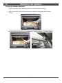
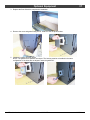
36
Optional Equipment
GreenStartTM Igniter – Firebrick and Housing Installation
This insert is compatible with the GreenStartTM automatic wood-stove igniter. This optional component
uses a specialized firebrick and housing that are shipped with the insert. If you are using the igniter, install
these components as shown below. The igniter is installed as shown in the instructions included with the
igniter kit.
Igniter Firebrick
Igniter Housing
HINT: If you are not using the igniter, store these components inside the fireplace cavity in case the
homeowner later decides to install them.
1. Remove the two firebricks from the front left corner of the firebox.
2. Place the igniter firebrick as shown below.
© Travis Industries
100-01273
4150514
Optional Equipment
37
3. Replace the floor firebrick to complete the installation.
4. Remove the cover and gasket using a 5/16” nutdriver. See the photos below.
5. Install the housing as shown below.
NOTE: The gasket’s hole patterns are unique. The housing must be re-installed in the same
configuration. If the holes are not aligned, rotate the gasket 90.
© Travis Industries
100-01273
4150514
38
Limited 7 Year Warranty
Register your warranty online at traviswarranty.com. Or, mail your warranty card to:
TRAVIS INDUSTRIES, INC., 12521 Harbour Reach Drive, Mukilteo, WA 98275.
TRAVIS INDUSTRIES, INC. warrants this appliance (appliance is defined as the equipment manufactured by Travis Industries,
Inc.) to be defect-free in material and workmanship to the original purchaser from the date of purchase as follows:
Check with your dealer in advance for any costs to you when arranging a warranty call.
Mileage or service charges are not covered by this warranty. This charge can vary from store to store.
Years 1 & 2 - COVERAGE: PARTS & LABOR
Firebox Assembly:
Firebox, Baffle Supports, Air Tubes, Air Channels, Convection Chamber
Door Assembly:
Air Control Assembly
Ceramic Glass
Cast Door, Latch Assembly, Glass Retainers
Slider Plate, Pressure Plate
Glass (breakage from thermal shock)
Catalytic Combustor
Catalytic Combustor (see “Conditions and Exclusions” # 10)
Firebrick
Accessories
Re-Installation Allowance
Breakage from thermal shock
Legs, Pedestal, Blower
In cases where heater must be removed from home for repairs, a partial cost of re-installation is covered
(pre-authorization required)
One-Way Freight Allowance
One-way freight allowance on pre-authorized repair done at factory is covered.
Exclusions: Paint, Gasketing
Years 3 THROUGH 5 - COVERAGE: PARTS & LABOR
Firebox Assembly:
Firebox, Baffle Supports, Air Tubes, Air Channels, Convection Chamber
Air Control Assembly
Slider Plate, Pressure Plate
Catalytic Combustor
Coverage for thermal crumbling and disintegration only
Door Assembly:
One-Way Freight Allowance
Cast Door, Latch Assembly, Glass Retainers
One-way freight allowance on pre-authorized repair done at factory is covered.
Exclusions: Paint, Gasketing, Accessories (Legs, Pedestal, Panels, Blower), Glass, Firebrick, ReInstallation Allowance
Years 6 THROUGH 7 - COVERAGE: PARTS
Firebox Assembly:
Firebox, Baffle Supports, Air Tubes, Air Channels, Convection Chamber
Air Control Assembly
Slider Plate, Pressure Plate
Door Assembly:
Cast Door, Latch Assembly, Glass Retainers
Exclusions: Paint, Gasketing, Accessories (Legs, Pedestal, Panels, Blower), Glass, Firebrick, ReInstallation Allowance, One-Way Freight Allowance, Labor Charges
Page 1 of 2
© Travis Industries
100-01273
4150514
Limited 7 Year Warranty
39
CONDITIONS & EXCLUSIONS
1. This new appliance must be installed by a qualified installer. It must be installed, operated, and maintained at all times in accordance with
the instructions in the Owner’s Manual. Any alteration, willful abuse, accident, neglect, or misuse of the product shall nullify this warranty.
2. This warranty is nontransferable, and is made to the ORIGINAL purchaser, provided that the purchase was made through an authorized
Travis dealer.
3. Discoloration and some minor expansion, contraction, or movement of certain parts and resulting noise, is normal and not a defect and,
therefore, not covered under warranty.
4. This warranty does not cover misuse of the stove. Misuse includes over-firing (operation where the connector or stove may glow red) of this
appliance can cause serious damage and will nullify this warranty. Misuse includes use of salt saturated wood, chemically treated wood, or
any fuel not recommended in the manual.
5. Damage to the stove due to improper break-in procedures (see manual for proper break in).
6. The salt air environment of coastal areas or a high humidity environment can be corrosive to the castings. These conditions can be corrosive
and can cause the cast iron to rust. This warranty does not cover any damage caused by a salt air or high humidity environment.
7. Damage to the appliance while it is in transit is not covered by this warranty, but is subject to a claim against the common carrier.
8. The warranty, as outlined within this document, does not apply to the chimney components or other non-Travis accessories used in conjunction
with the installation of this product. If in doubt as to the extent of this warranty, contact your authorized Travis retailer before installation.
9. Travis Industries will not be responsible for inadequate performance caused by environmental conditions such as nearby trees, buildings, roof
tops, wind, hills or mountains or negative pressure or other influences from mechanical systems such as furnaces, fans, clothes dryers, etc.
10. Damage to the catalytic combustor due to mishandling, removal, cleaning, or other handling is not covered. Degradation of the
combustor due to burning of anything other than natural cord wood is not covered. Burning of trash, garbage, artificial or paper logs,
gift wrappings, coal, lighter fluids, chemical starters, treated or painted wood, driftwood or chemical cleaners will void the combustor
warranty. These items contain chemicals that may cause the combustor to become deactivated.
11 This Warranty is void if:
a. The appliance has been operated in atmospheres contaminated by chlorine, fluorine or other damaging chemicals.
b. The appliance is subject to submersion in water or prolonged periods of dampness or condensation.
c. Any damage to the appliance, combustion chamber, heat exchanger or other components due to water, or weather damage which is
the result of, but not limited to, improper chimney/venting installation.
12. Exclusions to this Warranty include: injury, loss of use, damage, failure to function due to accident, negligence, misuse, improper installation,
alteration or adjustment of the manufacturer's settings of components, lack of proper and regular maintenance, damage incurred while the
appliance is in transit, alteration, or act of God.
13. This warranty excludes damage caused by normal wear and tear, such as paint discoloration or chipping, worn or torn gasketing, chipped or
cracked firebrick, etc. Also excluded is damage to the appliance caused by abuse, improper installation, modification of the appliance, or the
use of fuel other than that for which the appliance is configured (use cord wood only).
14. Damage to brass or plated surfaces caused by fingerprints, scratches, melted items, or other external sources left on the surfaces from the
use of abrasive cleaners is not covered in this warranty. Damage to the surfaces from over-firing (operation where the steel may glow red) is
not covered in this warranty.
15. TRAVIS INDUSTRIES, INC. is free of liability for any damages caused by the appliance, as well as inconvenience expenses and materials.
Incidental or consequential damages are not covered by this warranty. In some states, the exclusion of incidental or consequential damage
may not apply.
16. This warranty does not cover any loss or damage incurred by the use or removal of any component or apparatus to or from the Travis
appliance without the express written permission of TRAVIS INDUSTRIES, INC. and bearing a TRAVIS INDUSTRIES, INC. label of
approval. This warranty does not cover a stove repaired by someone other than a Travis Industries authorized dealer.
17. Any statement or representation of Travis products and their performance contained in Travis advertising, packaging literature, or printed
material is not part of this warranty.
18. This warranty is automatically voided if the appliance’s serial number has been removed or altered in any way. If the appliance is used for
commercial purposes, it is excluded from this warranty.
19. No dealer, distributor, or similar person has the authority to represent or warrant Travis products beyond the terms contained within this
warranty. TRAVIS INDUSTRIES, INC. assumes no liability for such warranties or representations.
20. Travis Industries will not cover the cost of the removal or re-installation of hearths, facing, mantels, venting or other components.
21. If for any reason any section of this warranty is declared invalid, the balance of the warranty remains in effect and all other clauses shall
remain in effect.
22. This warranty is the only warranty supplied by Travis Industries, Inc., the manufacturer of the appliance. All other warranties, whether
express or implied, are hereby expressly disclaimed and purchaser’s recourse is expressly limited to the warranties set forth herein.
IF WARRANTY SERVICE IS NEEDED:
1. If you discover a problem that you believe is covered by this warranty, you MUST REPORT it to your Travis dealer WITHIN 30 DAYS, giving
them proof of purchase, the purchase date, and the model name and serial number.
2. Travis Industries has the option of either repairing or replacing the defective component.
3. If your dealer is unable to repair your appliance’s defect, he may process a warranty claim through TRAVIS INDUSTRIES, INC.,
including the name of the dealership where you purchased the appliance, a copy of your receipt showing the date of the appliance’s
purchase, and the serial number on your appliance. At that time, you may be asked to ship your appliance, freight charges prepaid, to
TRAVIS INDUSTRIES, INC. TRAVIS INDUSTRIES, INC., at its option, will repair or replace, free of charge, your appliance if it is found
to be defective in material or workmanship within the time frame stated within this warranty. TRAVIS INDUSTRIES, INC. will return your
appliance, freight charges (years 1 to 3) prepaid by TRAVIS INDUSTRIES, INC., to your regional distributor, or dealership.
4. Check with your dealer in advance for any costs to you when arranging a warranty call. Mileage or service charges are not covered by
this warranty. This charge can vary from store to store.
5. Any appliance or part thereof that is repaired or replaced during the limited warranty period will be warranted under the terms of the
limited warranty for a period not to exceed the remaining term of the original limited warranty or six(6) months, whichever is longer.
Page 2 of 2
© Travis Industries
100-01273
4150514
40
Listing Label
Listing Label
DO NOT REMOVE THIS LABEL
CONTACT LOCAL BUILDING OR FIRE OFFICIALS ABOUT INSTALLATION AND RESTRICTIONS IN YOUR AREA.
SUITABLE FOR USE IN FACTORY-BUILT (Z.C.) FIREPLACES AND MASONRY FIREPLACES.
MODEL:
SERIAL NO:
LG FLUSH WOOD
with Hybrid-Fyre™
Report No. 100517991PRT-001
Control No. 4000515
Certified for USA and Canada
CONFORMS TO UL STD 1482; CERTIFIED TO ULC STD S628-1993
MANTEL
D
A
C
B
INSERT
Factory-Built
Masonry
Minimum Clearance to
(Z.C.) Fireplace
Fireplace
Combustibles and Hearth
Installations
Installations
Requirements
10.5 in. / 267 mm
A.
10.5 in. / 267 mm
5.5 in. / 140 mm
B.
5.5 in. / 140 mm
37 in. / 940 mm
*C.
37 in. / 940 mm
41 in. / 1042 mm
D.
41 in. / 1042 mm
16 in. / 407 mm
*E. (US)
16 in. / 407 mm
18 in. / 458 mm
*E. (CAN)
18 in. / 458 mm
6 in. / 153 mm
F. (US)
6 in. / 153 mm
8 in. / 204 mm
F. (CAN)
8 in. / 204 mm
* From the base of Fireplace Insert.
** Non-combustible hearth must be 1 in. / 26 mm above any combustible material.
*** A 16 in. / 407 mm non-combustible hearth must be 2 in. / 51 mm above any
combustible material.
COMBUSTIBLE FACING
COMBUSTUBLE SIDEWALL
FACTORY-BUILT (Z.C.) FIREPLACE OR MASONRY FIREPLACE INSTALLATION
F
E
HEARTH
EXTENSION
NON-COMBUSTIBLE
FIREPLACE FACING
Factory-Built (Z.C.) Fireplace installations require a fireplace chimney full re-line. Factory-Built (Z.C.) Fireplace chimney must have a minimum
cross-sectional area of 28.85 square inches / 733 square mm. A non-combustible hearth floor protection is also required that provides a thermal
resistance with an R value equal to 2.38 or greater (see chart above and / or owner’s manual for required sizing details).
Minimum 6 in. / 153 mm diameter Stainless Steel liner, full re-line required.
In Canada; a fireplace insert shall be installed with a continuous chimney liner extending from the fireplace insert to the top of the chimney. A
chimney liner shall be tested for conformance with Class 3 requirements of CAN/ULC-S635, Standard for Lining Systems for Existing Masonry or
Factory-Built Chimneys and Vents, or CAN/ULC-S640, Standard for Lining Systems for New Masonry Chimneys.
PREVENT HOUSE FIRES - Install and use only in accordance with the manufacturer’s installation and operating instructions. Contact your local
building or fire officials about restrictions and installation inspection in your area. Do not connect this unit to a chimney flue serving another
appliance.
This wood heater contains a catalytic combustor, which needs periodic inspection and replacement for proper operation. Consult owner’s manual
for further information. It is against the law to operate this wood heater in a manner inconsistent with operating instructions in the owner’s
manual, or if the catalytic element is deactivated or removed. CAUTION: the combustor used in this appliance (part no. 174-01111) is fragile and
must be handled carefully. Burning of metal foils, plastic, garbage, sulphur and diesel oil will render the catalyst in the combustor inactive. The
performance and durability of the catalytic combustor has not been evaluated as part of the certification.
Electrical Rating:
115V., 60 Hz, 1.8 Amps
Blowers:
# 228-10069 / 228-10070
Do not route power cord under or in front of appliance.
Replace glass only with 5mm neoceramic or
ceramic glass.
Manufactured by:
TRAVIS INDUSTRIES, INC.
12521 Harbour Reach Drive
Mukilteo, WA 98275
www.travisproducts.com
U.S. ENVIRONMENTAL PROTECTION AGENCY
Certified to comply with 2015 particulate emission standards. Not approved for sale after May 15, 2020. 0.58 g/h, Method 28, 5G2, 2015
DATE OF MANUFACTURE
2015
2016
2017
2018
Jan
Feb
Mar
Apr
May
Made in U.S.A.
© Travis Industries
Jun
Jul
Aug
Sep
Oct
Nov
Dec
1005
100-01273
4150514
Listing Information
© Travis Industries
100-01273
41
4150514
42
Index
Additional Accessories Needed for Installation .. 7
Additional Requirements for Canada ................. 7
Adjusting the Burn Rate ................................... 21
Air Tube Removal & Replacement ................... 34
Ash Removal .................................................... 21
Baffle Parts ....................................................... 33
Baffle Removal ................................................. 33
Before Your First Fire ....................................... 16
Blower and Electrical Parts .............................. 32
Blower Operation ............................................. 23
Brick Removal & Replacement ........................ 35
Bypass Operation ............................................. 18
Clean the Glass ................................................ 27
Cleaning the Air Duct and Blower .................... 29
Cleaning the Catalytic Combustor ................... 30
Combustor ........................................................ 33
Creosote - Formation and Need for Removal .. 28
Curing the Paint ............................................... 16
Daily Maintenance (while stove is in use) ........ 27
Dimensions ........................................................ 6
Do Not Burn List ............................................... 25
Door and Glass Inspection ............................... 28
Door Latch Adjustment..................................... 28
Door Parts ........................................................ 31
Drafting Performance ....................................... 12
Emissions and Efficiency ................................... 6
Face Installation ............................................... 14
Features ............................................................. 6
Fettle Installation .............................................. 12
Firebox Parts .................................................... 33
Firebrick and Baffle Inspection ......................... 29
Fireplace Altered Tag ......................................... 8
Fireplace Requirements ..................................... 8
Flue Installation ................................................ 13
GreenStartTM Igniter – Firebrick Installation ..... 36
© Travis Industries
Hearth Requirements ....................................... 10
Heating Specifications ....................................... 6
Hints for Burning .............................................. 24
Important Information ......................................... 2
Insert Placement Requirements ........................ 9
Insert Rollers .................................................... 12
Installation Options ............................................ 6
Introduction ........................................................ 2
Listing Label ..................................................... 40
Mantel Requirements ....................................... 10
Masonry Fireplace Requirements .................... 11
Monthly Maintenance (while appliance is in use)
..................................................................... 28
Normal Operating Sounds ............................... 23
Opening the Door............................................. 17
Over-Firing the Stove ....................................... 16
Overnight Burn ................................................. 23
Planning the Installation ..................................... 7
Preparation for Installation ................................. 7
Re-Loading the Stove ...................................... 23
Replacing the Door Gasket.............................. 31
Replacing the Glass ......................................... 31
Re-Routing the Electrical Cord to the Left Side
..................................................................... 15
Safety Notice.................................................... 16
Sealing the Flue to the Insert ........................... 13
Selecting Wood ................................................ 24
Starting a Fire .................................................. 20
Surround Panel Installation.............................. 14
Touch-Up Paint ................................................ 29
Troubleshooting ............................................... 26
Verify the Installation ....................................... 16
Wood Cutting and Storage .............................. 24
Yearly Maintenance ......................................... 29
100-01273
4150514