1
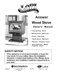
Rainier
(945/990)
Owner's Manual
• Freestanding Stove
• Mobile-Home Approved
• Alcove Approved
• Hearth-Stove Approved
• Masonry Fireplace Insert
• Zero-Clearance (Metal)
Fireplace Insert
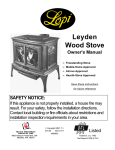
SAFETY NOTICE:
If this appliance is not properly installed, a house fire
may result. For your safety, follow the installation
directions. Contact local building or fire officials
about restrictions and installation inspection
requirements in your area.
Copyright 2015, T.I.
$10.00
100-01140
4150522
Listed
Tested to: U.L. 1482
Introduction
2
Introduction
We welcome you as a new owner of an Avalon Rainier wood-burning stove. In an Avalon Rainier you
have joined the growing ranks of concerned individuals whose selection of an energy system reflects
both a concern for the environment and aesthetics. The Avalon Rainier is one of the finest
appliances the world over. This manual will explain the installation, operation, and maintenance of
this appliance. Please familiarize yourself with the Owner's Manual before operating your appliance
and save the manual for future reference. Included are helpful hints and suggestions which will make
the installation and operation of your new appliance an easier and more enjoyable experience. We
offer our continual support and guidance to help you achieve the maximum benefit and enjoyment
from your appliance.
Important Information
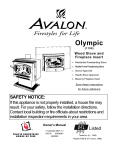
No other Avalon Rainier appliance has the same
serial number as yours. The serial number is
stamped onto the label on the back of the appliance.
Mail your Warranty Card Today, and
Save Your Bill of Sale.
This serial number will be needed in case you require
service of any type.
Model:
Serial Number:
Avalon Rainier
To receive full warranty coverage, you will
need to show evidence of the date you
purchased your appliance. Do not mail
your Bill of Sale to us.
Purchase Date:
Purchased From:
Travis Industries
We suggest that you attach your Bill of Sale
to this page so that you will have all the
information you need in one place should
the need for service or information occur.
100-01140
4150522
Table of Contents
General Information
3
Operating Your Appliance
Introduction & Important Information .......................... 2
Safety Precautions ..................................................... 4
Features & Specifications .......................................... 6
Safety Notice.............................................................. 23
Before Your First Fire ................................................. 23
Opening the Door ....................................................... 24
Starting a Fire ............................................................ 25
Adjusting the Burn Rate ............................................. 26
Air Control Settings..................................................... 26
Understanding Combustion........................................ 27
Optional Blower Operation ......................................... 28
Re-Loading the Stove ................................................ 28
Overnight Burn ........................................................... 28
Normal Operating Sounds.......................................... 28
Hints for Burning ........................................................ 29
Selecting Wood .......................................................... 29
Dry Wood is Key ................................................... 29
Testing Wood Moisture......................................... 29
Why Dry Wood is Key........................................... 29
Wood Cutting and Storage ................................... 29
Do Not Burn List.......................................................... 30
Troubleshooting ......................................................... 31
Stove Installation
Planning The Installation ............................................ 7
Floor Protection Requirements .................................. 8
Stove Placement Requirements ................................. 9
Clearances ................................................................. 9
Chimney Requirements.............................................. 10
Chimney Termination Requirements .......................... 11
Outside Air Requirements .......................................... 11
Alcove Installation Requirements ............................... 12
Mobile Home Requirements ....................................... 13
INSTALLATION DIAGRAMS
Standard Ceiling with a Factory Built Chimney ..... 14
Cathedral Ceiling with a Factory Built Chimney .... 14
Exterior Factory Built Chimney ............................. 15
Hearth Stove Positive Connection ........................ 15
Hearth Stove Direct Connection ........................... 16
Interior Masonry Chimney..................................... 16
Maintaining Your Appliance
Daily Maintenance...................................................... 32
Remove Ash ......................................................... 32
Clean The Glass ................................................... 32
Monthly Maintenance ................................................. 33
Door and Glass Inspection ................................... 33
Check For Creosote Buildup ................................ 33
Yearly Maintenance ................................................... 34
Touch Up Paint..................................................... 34
Blower Cleaning ................................................... 34
Firebrick and Baffle Inspection ............................. 34
Door Parts .................................................................. 35
Replacing the Glass ............................................. 35
Replacing the Door Gasket .................................. 35
Replacing the Door Handle .................................. 35
Firebox Parts.............................................................. 36
Floor & Side Firebrick Removal & Replacement... 36
Baffle Removal and Replacement ........................ 37
Air Tube Removal and Replacement .................... 37
Insert Installation
Planning The Installation ............................................ 17
Insert Size Requirements ........................................... 18
Insert Placement Requirements ................................. 18
Hearth Requirements ................................................. 18
Masonry Fireplace Requirements .............................. 19
Zero Clearance (Metal) Fireplace Requirements ....... 19
Drafting Performance ................................................. 20
Leveling Bolt Installation ............................................ 20
Block-Off Plate Installation ......................................... 21
INSTALLATION DIAGRAMS
Insert with Positive Connection............................. 22
Insert with Direct Connection (Masonry Fireplace) 22
Insert with Direct Connection (ZC Fireplace) ........ 22
Warranty
Warranty .................................................................... 38
Listing Information
Listing Information ...................................................... 39
Optional Equipment
Stove Legs ................................................................. 40
Pedestal ..................................................................... 40
Rear Blower Installation ............................................. 42
Outside Air Boot Installation ....................................... 43
Surround Panels ........................................................ 44
Front Blower ............................................................... 45
Index
Index .......................................................................... 46
Travis Industries
100-01140
4150522
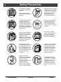
Safety Precautions
4
•
The viewing door must be
closed and latched during
operation.
•
Never block free airflow
through the air vents on this
appliance.
•
This appliance is designed
and approved for the
burning of cord wood only.
Do not attempt to burn any
other type of fuel other than
cord wood in this appliance,
it will void all warranties and
safety listings.
•
•
•
•
Travis Industries
Do not touch the appliance
while it is hot and educate
all children of the danger of
a high-temperature
appliance. Young children
should be supervised when
they are in the same room
as the appliance.
100-01140
Gasoline or other flammable
liquids must never be used
to start the fire or "Freshen
Up" the fire. Do not store or
use gasoline or other
flammable liquids in the
vicinity of this appliance.
•
Ashes must be disposed in
a metal container with a
tight lid and placed on a
non-combustible surface
well away from the home or
structure.
•
Keep furniture, drapes,
curtains, wood, paper, and
other combustibles a
minimum of 36" away from
the front of the appliance.
•
Contact your local building
officials to obtain a permit
and information on any
installation restrictions or
inspection requirements in
your area. Notify your
insurance company of this
appliance as well.
•
This appliance must be
connected to a listed high
temperature (UL 103 HT)
residential type chimney or
an approved masonry
chimney with a standard
clay tile, or stainless steel
liner.
Gas
ASHES
36"
This appliance must be
properly installed to prevent
the possibility of a house
fire. The instructions must
be strictly adhered to. Do
not use makeshift methods
or compromise in the
installation.
Inspect the chimney
connector and chimney at
least twice monthly and
clean if necessary.
Creosote may build up and
cause a house fire.
Do not connect this
appliance to any chimney
serving another appliance.
•
Ok
Type
HT
Clay
Liner
4150522
Safety Precautions
•
Mobile
Home
This
Manual
When installed in a mobile
home, this appliance must
be bolted to the floor, have
outside air, and not be
installed in the bedroom
(Per H.U.D. requirements).
Check with local building
officials.
•
Never try to repair or replace
any part of this appliance
unless instructions are given in
this manual. All other work
must be done by a trained
technician. Do not make any
changes or modifications to an
existing masonry fireplace or
chimney to install this
appliance.
•
Allow the appliance to cool
before carrying out any
maintenance or cleaning.
•
Maintain the door and glass
seal and keep them in good
condition.
•
Avoid placing wood against
the glass when loading. Do
not slam the door or strike
the glass.
•
Do not throw this manual
away. This manual has
important operating and
maintenance instructions
that you will need at a later
time. Always follow the
instructions in this manual.
5
•
Do not place clothing or
other flammable items on or
near this appliance.
•
This wood heater has a
manufacturer-set minimum
low burn rate that must not
be altered. It is against
federal regulations to alter
this setting or otherwise
operate this wood heater in
a manner inconsistent with
operating instructions in this
manual.
•
Overfiring the appliance
may cause a house fire. If a
unit or chimney connector
glows, you are overfiring.
•
Do not use a grate or other
device to elevate the fire off
of the firebox floor. Burn the
fire directly on the bricks.
•
Travis Industries, Inc.
grants no warranty,
implied or stated, for the
installation or
maintenance of your
appliance, and assumes
no responsibility of any
consequential damage(s).
Smoke and CO Detectors: Make sure your home has a working smoke detector, especially near any bedrooms. We
recommend having a smoke and/or CO detector in the same room as the wood heater for additional safety.
Proposition 65 Warning: Fuels used in gas, woodburning or oil fired appliances, and the products of combustion of such
fuels, contain chemicals known to the State of California to cause cancer, birth defects and other reproductive harm.
California Health & Safety Code Sec. 25249.6
Travis Industries
100-01140
4150522
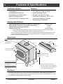
Features & Specifications
6
Installation Options:
•
•
•
•
•
Features:
Freestanding
Freestanding in an Alcove
Freestanding in a Mobile Home
Masonry Fireplace Insert
Factory-Built (Z.C.) Fireplace Insert
•
•
•
•
•
•
1.8 Cubic Foot Firebox Volume
Single Operating Control
Accepts Logs Up to 20" Long
Steel Plate Construction (1/4" & 3/16")
Heavy Duty Refractory Firebrick
Optional High-Tech Blower
Heating Specifications:
Approximate Maximum Heating Capacity (in square feet)*
Maximum BTU's per Hour (Cord Wood Calculation)
Overall Efficiency (Oregon Method)
Maximum Burn Time
*
800 to 1,800
71,800
71.7 %
Up to 9 Hours
Heating capacity will vary depending on the home's floor plan, degree of insulation, and the outside
temperature. It is also affected by the quality and moisture level of the fuel.
This model was not tested for efficiency however it is assigned a default efficiency of 63% by the EPA under
previous subpart AAA. Efficiency of this wood heater will be affected by the operational burn rate and the
moisture content of the wood used as fuel.
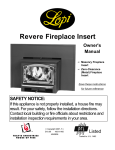
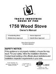
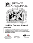
Dimensions:
Flue Location for Rainier-45
Note:
Measure side, corner,
4-1/4"
3-5/8"
and back clearances
from the stove top.
25-3/4" ****
19-1/8"
(from base)
The flue collar protrudes
21 1/8"*
3/4" above the stove top
Height:
Steel Legs (discontinued)..27-5/8"
Sculptured or Cast Legs..........29"
Pedestal............................32-3/8"
Insert Dimensions - Rainier 90
Depth into Fireplace** ........14-1/2"
Onto Hearth**** ....................5-1/8"
19-3/8"
* For inserts, add 3/4" for the flue collar.
Insert Dimensions - Rainier 45
** ZC (metal) fireplaces require an additional 1".
Depth into Fireplace** ...........9-1/2"
*** ZC (metal) fireplaces require an additional 2".
Onto Hearth**** .......................10"
**** Does not include hearth protection.
Emissions:
This heater meets the 2015 U.S. EPA’s crib wood emission limits for wood heaters sold after May 15,
2015. Tested to Method 28, 5H this heater has been shown to deliver heat at rates ranging from 11,200
to 40,000 BTU/hr and an emission value of 2.0g/h.
Travis Industries
100-01140
4150522
Stove Installation (for qualified installers only)
7
SAFETY NOTICE:
Please read this entire manual before you install and use your new room heater.
Failure to follow instructions may result in property damage, bodily injury, or even
death. Contact local building or fire officials about restrictions and installation
inspection requirements in your area.
Planning the Installation
We suggest that you have an authorized Travis Industries dealer install your stove. If you install the
stove yourself, your authorized dealer should review your plans for installation.
Check with local building officials for any permits required for installation of this stove and notify your
insurance company before proceeding with installation.
The location of your wood heater in your home will decide how affectively the heat produced will spread
throughout your house. Attention to the home design with consideration of natural convection and air
circulation should be taken into account when choosing the placement of your heater within the home.
Preparation for Installation
•
Check for damage to the exterior of the stove (dents should be reported, scratches can be fixed by
applying touch up paint).
•
Check the interior of the firebox (replace cracked firebrick and make sure baffle is in place).
The stove can be lightened by removing the firebricks and baffle. (pg 36) - replace before operation.
Stove Installation Considerations
The table below details the six most common types of installations and the considerations for each
type. Alternative methods of installation are available if they comply with local building codes.
Installation Type
Considerations
Standard Ceiling with a Factory Built Chimney
(Page 14)
• Requires ceiling and roof penetration
Cathedral Ceiling with a Factory Built Chimney
(Page 14)
• Cathedral style chimney support required
Exterior Factory Built Chimney
(Page 15)
• Uses two elbows to route chimney outside
• Provides best draft
• Provides best draft
• Exterior chimney is hidden from the room
• Elbows reduce draft
• Optional exterior chase reduces cold air blockage
Hearth Stove Positive Connection
(Page 15)
• Utilizes existing masonry or zero clearance (metal) chimney
• Provides good draft due to full reline
• Easier to clean than direct or horizontal hearth stove
Hearth Stove Direct Connection
(Page 16)
• Utilizes existing masonry or zero clearance (metal) chimney
• Requires construction of a "block-off plate"
• Draft reduced due to elbows & chimney cross section
Interior Masonry Chimney
(Page 16)
Travis Industries
• Utilizes existing masonry chimney (not approved for zero
clearance (metal) fireplaces)
100-01140
4150522
Stove Installation (for qualified installers only)
8
Floor Protection Requirements
•
Stove must be placed on the Travis Industries legs or Pedestal.
Floor protection must be
non-combustible and at least
.018" thick (26 gauge).
Min. 6”
Min. 6”
Min. 16”
Minimum 41-3/8"
Minimum
37-3/4"
Travis Industries
100-01140
4150522
Stove Installation (for qualified installers only)
9
Stove Placement Requirements
Clearances may be reduced by methods specified in NFPA 211, listed wall shields, pipe shields, or
other means approved by local building or fire officials.
•
Stove must be placed so that no combustibles are within, or can swing within (e.g. drapes,
doors), 36" of the front of the stove
•
If the stove is placed in a location where the ceiling height is less than 7', it must follow the
requirements in the section "Alcove Installation Requirements"
•
Must maintain the clearances to combustibles listed below (drywall, furniture, etc.):
Clearances
Corner Installations
Straight Installations
d
e
f
a
b
c
45°
NOTE:
Measure clearances to the stove top.
Minimum Clearance
(See the illustration above)
A
Sidewall to stove
B
Backwall to stove
C
Cornerwall to stove
D
Connector to sidewall
E
Connector to backwall
F
Connector to cornerwall
*
Rainier-45°
Singlewall
Reduced
Connector
Clearance*
14"
16"
17 1/2"
14"
11"
7 1/2"
24"
25 1/2"
15 1/2"**
10"**
16 1/2"**
12"**
Reduced clearance installations require one of the chimneys and connectors listed below:
• DURAVENT model DVL with DURATEC chimney
• DURAVENT model DVL with DURA-PLUS chimney
• AMERI-TEC model DCC with model HS chimney
• SECURITY model DL with SECURITY model ASHT or S2100 chimney
• METAL-FAB model DW with TG chimney
**
Rainier-90°
Singlewall
Reduced
Connector
Clearance*
14"
14"
14 1/2"
9 1/2"
11"
7 1/2"
24"
23 1/2"
15 3/4"
10 1/4"
20"
16"
• GSW Double Wall Chimney Connector with Super Chimney Twenty-One
• SELKIRK METALBESTOS model DS connector with model SSII chimney
• I.C.C. Excel (2100-2 Can.) (103-HT USA) chimney with HP connector
• Standard Masonry Chimney with any one of the above listed connectors
These are minimum clearances, not installation dimensions. Connector position will vary depending upon brand.
First establish the stove clearances, install the 45° connector to the stove, then determine the position of the connector.
NOTE:
Standard residential installations with reduced clearance connector may use the clearance determined by the
manufacturer of the connector for the connector to wall clearance or the clearance listed in this manual.
Offsets must be used to maintain the stove to wall clearance.
NOTE:
Reduced clearance connectors may not connect to the flue collar – order an appliance adapter for the
connector being used.
Travis Industries
100-01140
4150522
Stove Installation (for qualified installers only)
10
Chimney Requirements
•
•
DO NOT CONNECT THIS UNIT TO A CHIMNEY FLUE SERVING ANOTHER APPLIANCE.
Chimney connector must be a minimum 24 MSG black or 26 MSG blued steel (6" diameter).
Chimney must be used from the first floor or wall penetration to the chimney cap.
Use 6" diameter type UL 103 HT chimney from one manufacturer (do not mix brands) or code
approved masonry chimney with a flue liner.
Chimney connector and chimney must be fastened to the stove and each adjoining section.
Follow the chimney manufacturer's clearances and requirements.
Use the chimney manufacturer's fire stops, attic guards, roof supports, and flashings when passing
through a ceiling or thimble when passing through a combustible wall.
•
•
•
•
• No more than 180o of elbows (two 90o elbows, or two 45o & one 90o elbow, etc.).
NOTE: Additional elbows may be allowed if draft is sufficient. Whenever elbows are used the draft is
adversely affected. Additional chimney height may be required to boost draft.
Chimney Cap
(See the section
"Chimney Termination
Requirements" for
more details)
Factory Built
Chimney
Sections
}
Minimum System 15'
Maximum System 33'
Roof Penetration Equipment
(Roof Radiation Shield,
Flashing, Storm Collar)
}
Ceiling Penetration
Equipment (Attic
Radiation Shield with
Chimney Support)
Reduced
Clearance
Chimney
Connector
Sections
Minimum Air Space to
Combustibles (See
Chimney Manufacturer's
Instructions - usually 2")
}
Standard residential installations with
reduced clearance connector may use the
clearance determined by the manufacturer
of the connector for the connector to wall
clearance or the clearance listed in this
manual.
Mobile home installations must use the
the reduced clearance connector
clearances listed in this manual under
“Additional Requirements for Mobile Home
Installations”.
Floor
Protection
Stove Clearance
(as outlined in this manual)
Drafting
Performance
•
•
Draft is the force which moves air from the appliance up through the chimney. The amount
of draft in your chimney depends on the length of the chimney, local geography, nearby
obstructions and other factors. Too much draft may cause excessive temperatures in the
appliance and may damage the heater. Inadequate draft may cause backpuffing into the
room and `plugging' of the chimney. Inadequate draft will cause the appliance to leak
smoke into the room through appliance and chimney connector joints. An uncontrollable
burn or excessive temperature indicates excessive draft.
Standard residential installations may use single-wall connector (Mobile-Homes may not)
Standard residential installations with reduced clearance connector may use the clearance
determined by the manufacturer of the connector for the connector to wall clearance or the clearance
listed in this manual. Offsets must be used to maintain the stove to wall clearance. Mobile homes
must use the clearances listed in this manual under "Additional Requirements for Mobile Home
Installations".
Travis Industries
100-01140
4150522
Stove Installation (for qualified installers only)
11
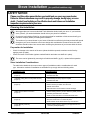
Chimney Termination Requirements
•
•
•
Must have an approved cap (to prevent water from entering)
Must not be located where it will become plugged by snow or other material
Must terminate at least 3' above the roof and at least 2' above any portion of the roof within 10'
Chimney must extend 2'
above any portion of the roof
within 10' of the chimney
Slanted Roofs
Chimney must
extend 3'
above the roof
Chimney must extend 2'
above any portion of the roof
within 10' of the chimney
Flat Roofs
Chimney must
extend 3'
above the roof
Outside Air Requirements
•
•
•
Required for mobile homes & in certain localities (check with building officials)
Must not be drawn from an enclosed space (garage, unventilated crawl space)
Requires the optional outside air boot (for legs) or pedestal.
When using outside air, find a location where the chimney and
outside air hole do not interfere with structural members of the home.
A hole must be cut
through the floor
protection and
floor and the
rodent screen
nailed in place
here (see the
optional equipment
instructions for
exact sizes)
Pedestal (with insulation)
directs air to the stove.
Outside
Air Boot
Optional Air Duct (must not be
longer than 15' and at least 16
square inches in cross section)
Air may be drawn from a ventilated
crawl space or use an air duct.
Travis Industries
100-01140
Outside air entrance must be placed so
it does not become blocked by snow.
4150522
Stove Installation (for qualified installers only)
12
Alcove Installation Requirements
Whenever the stove is placed in a location where the ceiling height is less than 7' tall, it is considered
an alcove installation. Because of the reduced height, the special installation requirements listed
below must be met.
•
Chimney connector and chimney must be one of the following types:
• DURAVENT model DVL with DURATEC chimney
• DURAVENT model DVL with DURA-PLUS chimney
• AMERI-TEC model DCC with model HS chimney
• SECURITY model DL with SECURITY model ASHT or S2100 chimney
• METAL-FAB model DW with TG chimney
• GSW Double Wall Chimney Connector with Super Chimney Twenty-One
• SELKIRK METALBESTOS model DS connector with model SSII chimney
• I.C.C. Excel (2100-2 Can.) (103-HT USA) chimney with HP connector
• Standard Masonry Chimney with any one of the above listed connectors
Rainier-45°
Minimum Clearance
(See the illustration below)
Sidewall to stove
Backwall to stove
Connector to sidewall
Connector to backwall
Maximum depth of alcove
Minimum width of alcove
Minimum height of alcove
•
16"
14"
25 1/2"
10"
48"
57 3/4"
84"
Non-Combustible Alcove
Rainier-90°
Combustible
Alcove
6"
4"
15 1/2"
2"
48"
37 3/4"
6" above stove top
14"
9 1/2"
23 1/2"
10 1/4"
48"
53 3/4"
84"
Non-Combustible Alcove
6"
2"
15 1/2"
2 3/4"
48"
37 3/4"
6" above stove top
Alcoves are classified as combustible or non-combustible. Non-combustible alcoves must have
walls and a ceiling that are 3 1/2" thick of a non-combustible material (brick, stone, or concrete).
This non-combustible material must be spaced and ventilated at least 1" off of all combustible
materials (walls, ceiling, etc.) to allow air to move around the non-combustible walls and ceiling.
All other alcoves are considered combustible. The clearances below must be met:
Non-combustible alcove
construction (on walls
and ceiling) - see the
explanation above.
d
e
Ventilated
air space
a
3 1/2" thick noncombustible
material
1" Min.
b
j
Combustible
materials
A
B
D
E
G
H
J
Combustible
Alcove
Non-combustible
reinforcer
h
g
Travis Industries
100-01140
4150522
Stove Installation (for qualified installers only)
13
Mobile Home Requirements
•
Outside air must be installed - see "Outside Air Requirements" on page 11
•
Chimney connector and chimney must be one of the following types:
• DURAVENT model DVL with DURATEC chimney
• DURAVENT model DVL with DURA-PLUS chimney
• AMERI-TEC model DCC with model HS chimney
• SECURITY model DL with SECURITY model ASHT or S2100 chimney
• METAL-FAB model DW with TG chimney
• GSW Double Wall Chimney Connector with Super Chimney Twenty-One
• SELKIRK METALBESTOS model DS connector with model SSII chimney
• I.C.C. Excel (2100-2 Can.) (103-HT USA) chimney with HP connector
• Standard Masonry Chimney with any one of the above listed connectors
NOTE: Reduced clearance connectors may not connect to the flue collar – order an appliance
adapter for the connector being used.
•
Stove placement must maintain the following clearances to combustibles (drywall, furniture, etc.)
Minimum Clearance
(See the illustration below)
A
B
C
D
E
F
*
Rainier-45°
Rainier-90°
(With Reduced Clearance
Connector)
(With Reduced Clearance
Connector)
Sidewall to stove
Backwall to stove
Cornerwall to stove
Connector to sidewall
Connector to backwall
Connector to cornerwall
16"
14"
7 1/2"
25 1/2"
10"*
12"*
14"
9 1/2"
7 1/2"
23 1/2"
10 1/4"
16"
These are minimum clearances, not installation dimensions. Connector position will vary depending upon
brand. First establish the stove clearances, install the 45° connector to the stove, then determine the position
of the connector.
Corner Installations
Straight Installations
d
e
f
a
b
c
NOTE:
Measure clearances to the stove top.
•
If using offsets, use the connector clearance listed to the
right, not the connector manufacturer's clearance.
•
The appliance must be secured to the floor (consult your
building official). Secure the outside air boot to the floor
and stove to insure the stove does not dislocate.
•
Mobile home installations require a spark arrester at the
chimney termination.
•
The appliance must be grounded to the chassis of the
mobile home (consult your building official).
WARNING:
DO NOT INSTALL IN SLEEPING ROOM.
CAUTION:
THE STRUCTURAL INTEGRITY OF THE MOBILE
HOME FLOOR, WALL, AND CEILING/ROOF MUST
BE MAINTAINED.
Travis Industries
100-01140
12-1/4”
Min.
Minimum Connector
Clearance
(as outlined above)
Minimum Stove
Clearance
(as outlined above)
4150522
14
Stove Installation (for qualified installers only)
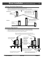
Standard
Ceiling with a
Factory Built
Chimney
Chimney Cap
(See the section "Chimney
Termination Requirements"
for more details)
}
Chimney Sections
Insulation
Follow the chimney
manufacturer's instructions
and clearances for floor
penetrations. A ceiling
support is required, an attic
insulation shield is required
where insulation is present.
}
Minimum Air Space to
Combustibles (See
Chimney Manufacturer's
Instructions - usually 2")
Minimum 15'
Maximum 33'
Chimney Connector Sections
Floor Protection
(See the section "Floor
Protection Requirements"
for more details)
Cathedral
Ceiling with a
Factory Built
Chimney
Stove Clearances
(See the section "Stove
Placement Requirements"
for more details)
Chimney Cap
(See the section "Chimney
Termination Requirements"
for more details)
Chimney Sections
Minimum Air Space to
Combustibles (See Chimney
Manufacturer's Instructions usually 2")
Chimney
Connector
Sections
Floor Protection
(See the section "Floor
Protection Requirements"
for more details)
Travis Industries
Follow the chimney
manufacturer's instructions
and clearances for roof
penetrations. A storm collar
and flashing are required
(some require a radiation
shield).
}
Follow the chimney
manufacturer's instructions
and clearances for roof
penetrations. A storm
collar, flashing, and
cathedral-style chimney
support are required
(some require a radiation
shield).
Minimum 15'
Maximum 33'
Stove Clearances
(See the section "Stove
Placement Requirements"
for more details)
100-01140
4150522
Stove Installation (for qualified installers only)
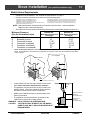
NOTE:
Exterior chimneys
are subject to
greater moisture
and creosote
accumulation due
to the lower
temperatures. An
insulated chase
will reduce these
accumulations
(the proper
clearances to the
chimney must be
maintained).
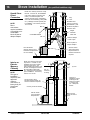
Hearth Stove
Positive
Connection
NOTE:
Most factory-built
chimney
manufacturers
make stainless
steel chimney
liners, either
flexible or rigid.
This provides a
wide variety of
installation
options. Make
sure to follow the
manufacturer's
instructions for
installation and
support.
Chimney Cap
(See the section "Chimney
Termination Requirements"
for more details)
}
Chimney Sections
Minimum Air Space to
Combustibles (See
Chimney Manufacturer's
Instructions - usually 2")
Wall Bands
and
Supports
Minimum 15'
Maximum 33'
Insulated Tee
(with cleanout )
Min. 18"
clearance to
ceiling
Chimney Connector
Sections
Floor Protection
(See "Floor
Protection
Requirements"
for details)
Stove Clearances
(See the section "Stove
Placement Requirements"
for more details)
NOTE: The entire fireplace and
chimney must be clean, undamaged,
and meet all local building codes
(UBC, etc.). Damage must be
repaired prior to installation. The
chimney must be 15' to 33' tall.
Travis Industries
Follow the chimney
manufacturer's
instructions and
clearances for roof
penetrations. A storm
collar and flashing are
required (some
require a radiation
shield).
}
Exterior
Factory Built
Chimney
15
Follow the chimney
manufacturer's
instructions and
clearances for wall
penetrations. A
wall radiation shield
(thimble) is
required.
Optional
insulated
chase
Cap and flashing
prevents water from
entering
The liner must be
stainless steel connector
or flexible vent. Follow
the liner manufacturer's
instructions for installation
and support.
Combustible
Mantle
Min. 18"
Airtight Insulated
Clean-Out
Remove damper
or wire it open
Floor Protection
(See the section
"Floor Protection
Requirements"
for more details)
See the section
"Stove Placement
Requirements" for
minimum clearances
required.
100-01140
4150522
16
Stove Installation (for qualified installers only)
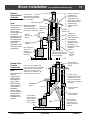
NOTE: The chimney must have a clay
tile liner. If it does not, the installation
must use a positive connection (full
reline). The entire fireplace and
chimney must be clean, undamaged,
and meet all local building codes (UBC,
etc.). Damage must be repaired prior
to installation. The chimney must be
15' to 33' tall.
Max. 8”
Hearth Stove
Direct
Connection
NOTE:
Direct
connections
require installation
of an airtight, noncombustible
block-off plate or
damper adapter.
Clay
Liner
Stainless steel
chimney connector
must Extend 1' past
the block-off plate or
to the flue liner
Airtight
Insulated
Clean-Out
Combustible Mantle
Min. 18"
Remove damper
or wire it open
Block-off plate or
damper adapter
Floor Protection
(See the section "Floor
Protection Requirements"
for more details)
Interior or
Exterior
Masonry
Chimney
NOTE:
This type of
installation
requires a UBC
approved
masonry
connector or a
factory built (U.L.
Listed) wall
thimble.
See the section
"Stove Placement
Requirements" for
minimum clearances
required.
NOTE: The chimney must have a
clay tile liner. If it does not, the
installation must use a positive
connection (full reline). The
entire fireplace and chimney must
be clean, undamaged, and meet
all local building codes (UBC,
etc.). Damage must be repaired
prior to installation. The chimney
must be 15' to 33' tall.
Clay Liner
Min. 18"
clearance
to ceiling
See the section "Stove
Placement Requirements" for
minimum clearances required.
Chimney connector sections
See the section
"Floor Protection
Requirements"
Travis Industries
This type of
installation requires
a UBC approved
masonry connector
or a factory built
(U.L. Listed) wall
thimble.
Make sure the
clean-out seals in
place.
100-01140
4150522
Insert Installation (for qualified installers only)
17
SAFETY NOTICE:
Please read this entire manual before you install and use your new room heater.
Failure to follow instructions may result in property damage, bodily injury, or even
death. Contact local building or fire officials about restrictions and installation
inspection requirements in your area.
Planning The Installation
We suggest that you have an authorized Travis Industries dealer install your stove. If you install the
stove yourself, your authorized dealer should review your plans for installation.
Check with local building officials for any permits required for installation of this stove and notify your
insurance company before proceeding with installation.
Preparation for Installation
•
Check for damage to the exterior of the inserts (dents should be reported, scratches can be fixed by
applying touch up paint).
•
Check the interior of the firebox (replace cracked firebrick and make sure baffle is in place).
The stove can be lightened by removing the firebricks and baffle. (pg 26) - replace before operation.
Insert Installation Considerations
•
This insert is approved for installation into an existing masonry or zero clearance (metal) fireplace.
Depending upon your installation concerns, several options are yours to provide the most desirable
installation. The sections that follow detail the requirements that must be met for a safe installation.
To further help installation, the most common types of installations are explained in table below. Prior
to installing your insert make a detailed plan with dimensions to double-check them against all of the
requirements listed.
Installation Type
Insert with Positive Flue (Full Reline)
(Page 22)
Insert with Direct Connect Flue
(Page 22)
Considerations
• Utilizes existing masonry or zero clearance fireplace
• Provides best draft
• Easiest to clean
• Utilizes existing masonry or zero clearance fireplace
• Provides good draft
• Requires fireplace block-off plate - see page 18
Surround Panels
•
The insert must be installed with surround panels (see page 44).
Travis Industries
100-01140
4150522
Insert Installation (for qualified installers only)
18
Insert Size Requirements (see Illustration below)
Minimum Fireplace
Size
Co
mb
us
tib
le
Ma
nte
a
b
c
d
e
l
j
No
n-C
om
i
a
h
bu
stib
le
b
Fa
f
cin
g
g
h
i
d
No
c
n-C
om
bu
stib
g
le
e
j
He
art
h
f
Masonry
Fireplace
Z.C. (Metal)
Fireplace
21 7/8"
21 7/8"
25 3/4"
25 3/4"
14 1/2"
9 1/2"
21 1/8"
26"
41 3/4"
51 3/4"
50 5/8"
35 5/8"
52 5/8"
37 5/8"
21 7/8"
21 7/8"
27 3/4"
27 3/4"
15 1/2"
10 1/2"
21 1/8"
26"
41 3/4"
49 3/4"
33 1/8"
N/A
45 1/8"
N/A
Height (front)
Height (rear)
Width (front)
Width (rear)
Depth Rainier-90
Depth Rainier-45
Hearth Rainier-90*
Hearth Rainier-45*
Hearth Width
Facing Width
Facing Height
with Mantel Shield
Mantel Height
with Mantel Shield
* This is the distance the insert protrudes from the
fireplace opening plus the required 16" of hearth
extension.
Insert Placement Requirements
•
The insert must be placed so that no combustibles are within, or can swing within (e.g. drapes,
doors), 36" of the front of the insert
•
Insert and hearth must be installed on a level, secure floor
•
The minimum clearances, facing, and hearth requirements in the illustration below must be met
(follow the clearances for the type of fireplace being used - either masonry or zero-clearance).
Masonry
Fireplace
ZC (Metal)
Fireplace
k Sidewall to Insert
l
Side Facing
m Top Facing
w. Mantel Shield
n Mantel to Insert
w. Mantel Shield
o Hearth (Front)*
p Hearth (Side)
q Front of Insert
14"
13"
29 1/2"
14 1/2"
31 1/2"
16 1/2"
16"
8"
36"
30"
12"
12"
N/A
24"
N/A
16"
8"
36"
x
5 1/8"
10"
5 1/8"
10"
Minimum Clearances
Co
mb
us
tib
le
Co
n
Side
Wall
Ma
mb
nte
us
l
tib
le
To
pF
ac
ing
m
k
Fa
l
cin
g
p
No
q
n-C
o
He mbu
art sti
h ble
o
x
Hearth Ext. Rainier-90
Hearth Ext. Rainier-45
* Does not include the distance the insert
extends onto the hearth (dimension "x").
Hearth Requirements
•
Must extend 16" in front of the insert and 8" on both sides
•
Must be non-combustible 1/4" thick insulating board with a thermal conductivity of K = 0.72
Travis Industries
100-01140
4150522
Insert Installation (for qualified installers only)
19
Masonry Fireplace Requirements
•
Chimney must have a clay tile liner or a stainless steel liner (positive connection)
•
Entire fireplace, including chimney, must be clean and undamaged. Any damage must be repaired
prior to installation of the insert
•
Chimney height: 15' minimum; 33' maximum.
•
Entire fireplace, including chimney, must meet local building requirements
Zero-Clearance (Metal) Fireplace Requirements:
Must be manufactured by one of the following manufacturers:
• Marco
• Majestic
• Heat N Glo
• Lennox
• Heatilator
• Martin
• Preway
• Tempco
• Superior
• Monesson
Entire fireplace, including chimney, must meet local building requirements
Chimney height: 15' minimum; 33' maximum.
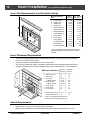
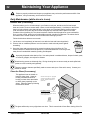
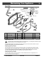
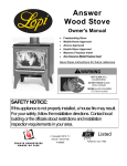
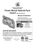
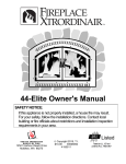
The damper ("A") and grate ("B") must be
removed (see illustration to the right). The
smoke shelf ("C"), internal baffles ("D"),
screen ("E"), and metal or glass doors ("F")
may be removed (if applicable). The
masonry lining ("G"), insulation ("H"), and
any structured rigid frame members (metal
sides, floor, door frame, face of the
fireplace, etc. – "I") may not be removed or
altered.
H
A
C
F
D
I
E
B
G
The chimney on the ZC fireplace must be listed per UL 127 or ULC 610-M87 for all installations. Any
thermal protection component of the fireplace or chimney must remain in place. The fireplace and
chimney must be inspected prior to installation. A NFPA 211 Level II inspection is recommended.
Repairs must be made prior to insert installation. The base of the fireplace must be structurally
sound and able to support the weight of the insert.
The stainless steel liner must be 6” diameter and extend the full height of the chimney (also called a
positive connection or full re-line). This liner must meet type HT (2100°F) requirements per UL 1777
(USA) or ULC S635 with “0” clearance to masonry (Canada). The liner must be attached to the insert
flue collar and to the top of the existing chimney.
We recommend using the listed Travis ZC Liner Kit from Duravent (SKU 98900046, 47, or 48). If you
do not use this kit, you must use the original ZC chimney cap.
The liner support and cap at the top of the chimney must not reduce air flow for the existing air-cooled
chimney system. The Travis ZC Liner Kit includes a cap that meets this provision.
To prevent air from passing up the ZC fireplace chimney (the gap between the liner and chimney) we
recommend sealing the area near the damper. Use non-combustible material to seal this area (nonbacked fiberglass insulation or kaowool).
The convection air channel on the fireplace must not be blocked. Do not block any louvers, grills, or
air passages on the front of the fireplace.
Entire fireplace, including chimney, must meet local building requirements. Permits may be required
for installation. Final approval is contingent upon the authority having local jurisdiction. Inform you
insurance agent of this fireplace insert.
Travis Industries
100-01140
4150522
20
Insert Installation (for qualified installers only)
Drafting Performance
This appliance relies upon natural draft to operate. External forces, such as wind, barometric
pressure, topography, or factors of the home (negative pressure from exhaust fans, chimneys, air
infiltration, etc.), may adversely affect draft. Travis Industries can not be responsible for external
forces leading to less than optimal performance.
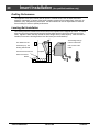
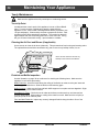
Leveling Bolt Installation
Two leveling bolts are included to level the insert if the fireplace has a stepped-up hearth. To install,
raise the rear of the insert up and insert the leveling bolts into the holes in the rear corners of the
insert. Adjust the bolts until they extend the same height as the hearth steps up. After the insert is
installed, fine-tune the leveling bolts to level the insert (see the illustration).
The leveling bolts go
This distance is the
into the holes at the
hearth step-up. The
rear corners of the
leveling bolts should
insert.
stick out this far from the
Fireplace
base of the insert.
Hearth
Travis Industries
100-01140
4150522
Insert Installation (for qualified installers only)
21
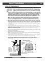
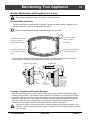
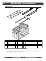
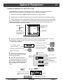
Block-Off Plate Installation
Whenever this appliance is installed with a direct connection a block-off plate, or other noncombustible seal-off device (e.g. damper adapter), will need to be installed. This device is used to
seal the chimney, insuring no smoke enters the home and providing the chimney system with a seal
to promote draft. The directions below detail the steps for construction and installation of a block-off
plate.
1. Determine a location for the block-off plate at the top of the firebox below the damper area (make
it high enough to allow installation of the connection pipe). The location should be level and in an
area where it can be mounted easily. Measure the width at the rear ("A") and front ("B") of the
firebox at the height where the block-off plate will be installed (see the illustration below). Then
measure the depth of the location where the block-off plate will be installed ("C").
NOTE: Most masonry fireplaces have square fireboxes while certain zero-clearance (metal)
fireplaces often have domed firebox tops. This makes zero-clearance block-off plates more
difficult to install. To simplify the procedure, insulation may be used to seal the rounded edges.
2. Make a cardboard template of the measurements, but add a 2" flange to each side. This flange
will be used to mount the block-off plate to the inside of the firebox. Bend the flanges downwards
on the template and place it inside the fireplace. If the template fits correctly in its planned
location, go to the next step. If it does not, make a new template with the appropriate corrections
until it fits correctly.
3. With the template in place, mark the location of the flue (see “Dimensions” on page 6). This
location approximates the center of the flue when the insert is in place (a slight offset may occur
based upon insert and block-off plate placement). Remove the template and cut a 6 1/4"
diameter hole centered on this mark.
4. Make the block-off plate of 24 gage or thicker steel to match the template. Drill two holes in each
flange for mounting the plate.
5. Mount the block-off plate using masonry screws.
NOTE: Use sheet metal screws on zero-clearance (metal) fireplaces (screws need only be long
enough to penetrate the first layer of metal).
6. Insulate the block-off plate using high-temperature fiberglass insulation (Kaowool® or equivalent)
and furnace cement (allow the cement to dry for at least 24 hours before burning).
7. After placing the appliance and installing the pipe through the block-off plate, use hightemperature fiberglass insulation and furnace cement to seal any cracks between the pipe and
block-off plate.
Block-Off Plate Template
Damper
2" Flanges
(for attaching
Measurement
"A"
the block-off
plate)
Measurement
"C"
See the
dimensions to
determine the
location of the
center of the
flue.
Travis Industries
B
C
A
Measurement "B"
Firebox
See the dimensions to determine the location of
the center of the flue.
100-01140
4150522
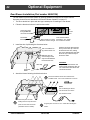
Insert Installation (for qualified installers only)
22
Insert with
Positive
Connection
NOTE:
Most factory-built
chimney
manufacturers
make stainless
steel chimney
liners, either
flexible or rigid.
This provides a
wide variety of
installation
options. Make
sure to follow the
manufacturer's
instructions for
installation and
support.
Insert with Direct
Connection
(Masonry
Fireplace)
NOTE:
Direct
connections
require installation
of an airtight
block-off plate or
damper adapter
(see "Block-off
Plate Installation"
on page 21).
Travis Industries
Install a non-combustible
cover plate to prevent water
from entering the chimney
NOTE: This installation may be
used with a masonry or zero
clearance fireplace. The
requirements in the section
"Masonry Fireplace Requirements"
or "Zero Clearance Fireplaace
Requirements" must be fulfilled
prior to installation.
Combustible Mantle
Cap (prevents water
from entering)
Flue Liner
The liner must be
stainless steel
connector or flexible
vent. Follow the liner
manufacturer's
insturctions for
installation and
support.
Airtight Insulated
Clean-Out
Surround Panels
Remove damper
or wire it open
See the section "Insert
Placement Requirements" for
minimum clearances and
hearth required.
NOTE: This installation may be
used with a masonry or zero
clearance fireplace. This
illustration depicts a masonry
insert, all requirements in the
section "Masonry Fireplace
Requirements" must be fulfilled
prior to installation.
Flue
Liner
Stainless steel
chimney connector
must Extend 1' past
the block-off plate or
to the flue liner
Combustible Mantle
Airtight
Insulated
Clean-Out
Surround Panels
See the section
"Insert Placement
Requirements" for
minimum clearances
and hearth required.
100-01140
Remove
damper
or wire it
open
Block-off plate or
damper adapter
4150522
Operating Your Appliance
23
Safety Notice:
If this appliance is not properly installed, a house fire may result. For your safety, follow the installation
directions. Contact local building or fire officials about restrictions and installation inspection
requirements in your area.
Read and follow all of the warnings on pages 4 and 5 of this manual.
Before Your First Fire
Verify the Installation
Before starting the stove, verify that the stove is properly installed and all of the requirements in this
manual have been followed.
Keep all flammable materials 36" away from the front of the stove (drapes, furniture, clothing, etc.).
Curing the Paint
2 to 4 hours
Follow the steps below to cure the paint (first fire):
a) Open doors and windows in the room to ventilate the heater
during the curing process.
b) Vacate the room. The fumes from the initial heating process
are non-toxic but may be unpleasant.
c) Slowly bring the heater to a medium burn (400°F/204°C) for 45
minutes. Then increase the burn temperature to a hot burn
(600°F/315°C) for an additional 45 minutes. This will cure the
paint.
Door Gasket - The door gasket might adhere to the paint on the
front of the heater. Leave the door slightly ajar for the first fire
and be careful when opening the door after the first fire.
Carbon Monoxide (CO) Emissions
Smoke from wood heaters contain CO. This gas is an indication of incomplete combustion and is
detrimental to the environment and to your health. The more visible the smoke, the higher the CO
levels. Burning dry wood is the most significant step you can take to reduce CO emissions. It is also
important to understand the combustion process so you can burn your heater efficiently. Read the
manual thoroughly so that you can operate your heater in the most efficient and clean manner
possible.
Over-Firing the Stove
DO NOT OVERFIRE THIS HEATER: Attempts to achieve heat output rates that exceed heater
design specifications can result in permanent damage to the heater.
This stove was designed to operate at a high temperature. But due to differences in vent
configuration, fuel, and draft, this appliance can be operated at an excessive temperature. If the
stove top or other area starts to glow red, you are over-firing the stove. Shut the air control down to
low and allow the stove to cool before proceeding.
Travis Industries
100-01140
4150522
24
Operating Your Appliance
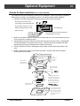
Opening the Door
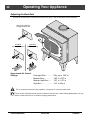
Turn the handle clockwise to un-latch.
Swing the door open.
The door becomes hot during use. Use a glove to open the door if the handle is hot.
To prevent smoke from entering the room, open the door a small amount and let air enter the firebox.
This stabilizes the air flow before opening the door completely.
Travis Industries
100-01140
4150522
Operating Your Appliance
25
Starting a Fire
Since the dawn of time man has debated the best way to start a fire. Some use the boy-scout "teepee", some prefer the "tic-tac-toe" stack. Either way, review the hints and warnings below to ensure
proper fire starting.
•
Make sure the air control is pushed in. If additional air is needed, open the doors 1/4" during the first
five minutes of start-up.
Never use gasoline, gasoline-type lantern fuel, kerosene, charcoal lighter fluid, or similar liquids to start
or "freshen up" a fire in this stove. Keep all such liquids well away from the stove while it is in use.
If using a firestarter, use only products specifically designed for stoves - follow the manufacturer's
instructions carefully.
If the smoke does not pass up the chimney, ball up one sheet of newspaper, place it in the center of the
firebox and light it. This should start the chimney drafting (this eliminates "cold air blockage").
Use plenty of kindling to ensure the stove reaches a proper temperature. Once the kindling is burning
rapidly, place a few larger pieces of wood onto the fire.
Travis Industries
100-01140
4150522
26
Operating Your Appliance
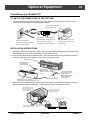
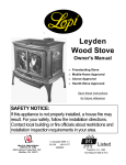
Adjusting the Burn Rate
Use the air control slider to control the burn rate of the stove. See the illustration below for details.
Use the air control to
change the burn rate.
Low Burn
(air control closed)
High Burn
(air control open)
Approximate Air Control
Settings:
Overnight Burn ............
Medium Burn ...............
Medium High Burn .......
High Burn ....................
Fully out to 1/64" in
1/64" to 1/32" in
1/32" to 1/16" in
1/16" to fully in
The air control becomes hot during operation - use gloves or a tool to prevent burns.
The air control may take several minutes to influence the burn rate. When making adjustments, you may
wish to let the stove burn for 10 minutes to gauge performance.
Travis Industries
100-01140
4150522
Operating Your Appliance
27
Understanding Your Heater’s Combustion System
This heater uses a dual combustion system detailed below:
Primary Combustion: This is the combustion (fire) that takes place directly on the wood. Primary combustion
determines how fast the fire burns. Air for primary combustion is supplied through the air control. When you
adjust the air control you control the amount of air that reaches the fire and creates primary combustion. The air
control supplies air to the air wash (the air holes above the door opening – used to help clean the glass) and
through the pilot orifice (center bottom of the door opening). By using the air control, and supplying air through
these two openings, you control primary combustion.
Secondary Combustion: This is the combustion (fire) that does not contact the wood. Secondary combustion
burns the visible emissions or smoke that is not consumed during primary combustion. During some phases of
combustion you will see secondary combustion. It appears as a glowing flame at the top of the firebox. Air for
secondary combustion is supplied by the air tubes at the top of the firebox.
Items to Consider:
During medium and high burn rates the stove will manage secondary and primary combustion on its own.
When the heater is set to a low burn rate more care is needed to ensure the secondary combustion system
works properly. Make sure the stove is hot and a good coal bed is established before adjusting your heater to
low burn.
Understanding the combustion system in this heater will help minimize the visible emissions this heater
releases into the environment. The primary pilot orifice at the center bottom of the door opening is designed
to help the secondary combustion at low burn settings. The pilot provides a small amount of air that burns up
through the fuel load providing the heat and flame needed for the secondary system to ignite. The air tubes
under the baffle need to remain ignited for low burns to be effective.
As you load your heater for a low burn, take care in placing the wood. This will affect how well your
secondary system works as the wood is consumed. Do not block the pilot orifice. Stack wood so the pilot air
can burn its way up between the pieces, helping your heater burn effectively throughout the low fire. This will
reduce the visible emissions your heater produces and increase the amount of heat you get from the wood. If
you are unsure how well your heater is burning look at the chimney cap to monitor visible emissions.
Burning Your Heater
Starting a Fire: When starting a fire it is imperative to get the heater hot and drafting as quickly as possible.
This promotes combustion and reduces emissions. There are many ways to start a fire and you will become
adept as you become familiar with the way your heater burns. Before you start, make sure your burn rate setting
(air control) is all the way open and the by-pass (if equipped) is open. We suggest that you use a layer of
crumpled newspaper covered with a three layers of small kindling, stacked tic tac toe style with approximately ½”1”gaps between them. Continue to layer wood on top of the kindling with the same air gaps using slightly bigger
pieces increasing in size as you stack upward with the final layer being 3-5” diameter pieces loaded on the top.
This should fill the firebox. Light the newspaper in several places near the door opening. Shut the door but do not
latch it, creating a small opening to allow air to feed the kindling fire. Never leave your heater unattended if your
door is not latched shut. While the kindling burns the fire will heat and ignite the larger pieces above. Once the
whole load is burning shut and latch the door leaving the burn rate on high. Depending on your heater, the
chimney, and the outside environment, you may need to leave your bypass open for up to 20 minutes after
lighting the fire. If the fire dies when you shut the bypass you will need to leave it open longer. The presence of a
hot coalbed is critical to good combustion. We cannot overstate the importance of a hot coal bed before slowing
your burn rate or re-loading your heater. We recommend that you allow the first ignition load of wood to burn
through at the high burn rate. This will get your heater up to temperature and establish a coal bed.
Reloading: When reloading a hot heater set the burn rate on high for at least 15 min before slowing it down.
Low Burn: If preparing for an overnight or low burn a longer heat up period may be necessary. Reload the
heater full of wood making sure there are air gaps between the wood pieces so the pilot air can burn up through
the middle load keeping the secondary combustion system hot and active throughout the burn. After loading, burn
the heater on high for at least 15 minutes before setting the air control to low. Excessive creosote buildup (or
sooting) in the heater at the end of a low burn signifies that the heater was not hot enough and the wood load was
not burned long enough on high after loading before shutting down the air control.
Travis Industries
100-01140
4150522
Operating Your Appliance
28
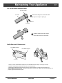
Optional Blower Operation
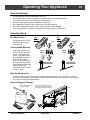
The blower will turn on once the stove is up to temperature. This is typically 15 to 30 minutes after
starting the fire. Follow the directions below to alter the blower speed.
OFF
HIGH
LOW
Turn the dial all the way counterclockwise until it clicks off.
The high position is all the way counterclockwise, without clicking off.
Turn the dial all the
way clockwise.
OFF
OFF
OFF
HI
LO
HI
LO
BLOWER
CONTROL
BLOWER
CONTROL
HI
LO
BLOWER
CONTROL
The blower may be used to affect heat output (i.e.: to reduce heat output, turn the blower down).
Route the power cord in a location where it will not come in contact with the appliance or become hot.
Re-Loading the Stove
1
2
3
Follow the directions below to minimize smoke spillage while re-loading the stove.
Push the air control all the way in (high burn).
Open the door slightly. Let the airflow inside the firebox to stabilize before opening the doors fully.
Load wood onto the fire.
Overnight Burn
1
2
3
4
This stove is large enough to accommodate burn times up to eight hours. Follow the steps below to
achieve an overnight burn.
Move the air control to high burn and let the stove become hot (burn for approximately 15 minutes).
Load as much wood as possible. Use large pieces if possible.
Let the stove burn on high for 15 minutes to keep the stove hot, then turn the air control to low.
In the morning the stove should still be hot, with embers in the coal bed. Stir the coals and load small
pieces of wood to re-ignite the fire, if desired.
Differences if chimney height and draft may lower overall burn times.
Normal Operating Sounds
Creaks and Clicks:
The 3/16" and 1/4" steel may creak or click when the
stove heats up and cools down - this is normal.
Blower Sounds:
The blower will make a slight "humm" as it
pushes air through the stove.
Hint:
Make sure the leveling bolts on legs are extended preventing the hearth from amplifying any vibrations.
Travis Industries
100-01140
4150522
Operating Your Appliance
29
Hints for Burning
•
•
•
•
•
•
•
Get the appliance hot before adjusting to low burn
Use smaller pieces of wood during start-up and high burns to increase temperature
Use larger pieces of wood for overnight or sustained burns
Stack the wood tightly together to establish a longer burn
Be considerate of neighbors & the environment: burn dry wood only
Burn small, intense fires instead of large, slow burning fires when possible
Learn your appliance's operating characteristics to obtain optimum performance
Selecting Wood
Dry Wood is Key
Dry wood burns hot, emits
less smoke and creates
less creosote.
Wet
Wood
Dry
Wood
Leads
To
Leads
To
Testing Wood Moisture
Split wood stored in a dry
area will be fully dry within
a year. This insures dry
wood. If purchasing wood
for immediate use, test the
wood with a moisture
meter. Some experienced
wood burners can measure
wood moisture by knocking
pieces together and
listening for a clear "knock"
and not a "thud".
Less
Heat
More
Heat
Leads
To
Leads
To
More Smoke
and Creostoe
Less Smoke
and Creostoe
Why Dry Wood is Key
Wet wood, when burned, must release water stored within the wood. This cools the fire, creates
creosote, and hampers a complete burn. Ask any experienced wood burner and he or she will agree:
dry wood is crucial to good performance.
Wood Cutting and Storage
Cut wood to length and
chop into quarters.
Store the wood off the ground in a
covered area. Allow for airflow
around the wood to dry the wood.
Air Flow
Air Flow
Air Flow
Travis Industries
100-01140
4150522
30
Operating Your Appliance
DO NOT BURN LIST
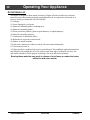
This heater is designed to burn natural wood only. Higher efficiencies and lower emissions
generally result when burning air dried seasoned hardwoods, as compared to softwoods or to
green or freshly cut hardwoods. DO NOT BURN:
(1) Garbage;
(2) Lawn clippings or yard waste;
(3) Materials containing rubber, including tires;
(4) Materials containing plastic;
(5) Waste petroleum products, paints or paint thinners, or asphalt products;
(6) Materials containing asbestos;
(7) Construction or demolition debris;
(8) Railroad ties or pressure-treated wood;
(9) Manure or animal remains;
(10) Salt water driftwood or other previously salt water saturated materials;
(11) Unseasoned wood; or
(12) Paper products, cardboard, plywood, or particleboard. The prohibition against burning these
materials does not prohibit the use of fire starters made from paper, cardboard, saw dust, wax
and similar substances for the purpose of starting a fire in an affected wood heater.
Burning these materials may result in release of toxic fumes or render the heater
ineffective and cause smoke.
Travis Industries
100-01140
4150522
Operating Your Appliance
31
Troubleshooting
Problem
Possible Cause
Smoke Enters Room During
Start-Up
•
Cold Air Blockage - burn a piece of newspaper to
establish a draft.
•
Close the doors - if the flame is not getting enough air,
first make sure the air control is open (all the way in).
If additional air is needed, a small crack in the door is
all that is needed.
•
Cold Air Blockage - burn a piece of newspaper to
establish a draft.
•
Not enough starter paper - use additional newspaper if
necessary.
•
Not enough air - first make sure the air control is open
(all the way in). If additional air is needed, a small
crack in the door is all that is needed.
•
Let the air stabilize before fully opening the door.
Push the air control in before opening the door. Then
open the door approximately 1 inch. Let air go into the
firebox for a few seconds. Once the smoke appears to
be flowing up the chimney consistently, open the door.
•
Insufficient Draft - Chimney height and outside
conditions can negatively affect draft. In these cases a
small amount of smoke may enter the home. Adding
more pipe or a draft-inducing cap may help.
•
Wood is Wet - see the section "Selecting Wood" on
page 29 for details on wood.
•
Insufficient Draft - Chimney height and outside
conditions can negatively affect draft. In these cases
the fire may burn slowly. Adding more pipe or a draftinducing cap may help.
•
Air Control is Not Wide Open - Make sure the air
control is all the way in. Slide the control back and
forth to insure the control is not stuck.
•
Stove is Not Up to Temperature - This is normal. The
blower will come on when the stove is hot - usually 15
to 30 minutes.
•
Electricity is Cut to the Blower - Check the household
breaker or fuse to make sure it is operable.
•
This appliance burns for up to 8 hours. Depending
upon wood, draft, and other factors, the burn time may
be shorter. Make sure the doors are sealing and not
allowing air into the firebox - See the section "Door
and Glass Inspection" on page 33 for details.
•
Check the ash bed for coals. Often, coals are still
glowing under a slight bed of flyash. By raking these
into a pile you can re-start your stove quickly.
Kindling Does Not Start Fire Smolders
Smoke Enters Room While
Re-Loading
Stove Does Not Burn Hot
Enough
Blower Does Not Run
Stove Does Not Burn Long
Enough
Travis Industries
100-01140
4150522
Maintaining Your Appliance
32
Failure to properly maintain and inspect your appliance may reduce the performance and life of the
appliance, void your warranty, and create a fire hazard.
Daily Maintenance (while stove is in use)
Remove Ash (if necessary)
Whenever ashes get 3 to 4 inches deep in your firebox or ash pan, and when the fire has burned
down and cooled, remove excess ashes. Leave an ash bed approximately 1 inch deep on the firebox
bottom to help maintain a hot charcoal bed. Let the stove cool completely before removing ashes
(wait at least two hours after the last coal has extinguished). Ashes should be placed in a metal
container with a tight-fitting lid. The closed container of ashes should be placed on a noncombustible
floor or on the ground, away from all combustible materials, pending final disposal. The ashes should
be retained in the closed container until all cinders have thoroughly cooled.
Follow the directions below to remove ash.
1
Let the stove cool completely (at least two hours after the last coal has extinguished).
2
Place a cloth or cardboard protector over the hearth to catch ash and protect against
scratching.
3
Open the doors and scoop the ash into a metal container with a tight fitting lid. The
closed container of ashes should be placed on a noncombustible floor or on the ground,
away from all combustible materials, pending final disposal.
ASHES
Improperly disposed ashes lead to fires. Hot ashes placed in cardboard boxes, dumped in back yards,
or stored in garages, are recipes for disaster.
Wood-burning stoves are inherently dirty. During cleaning have a vacuum ready to catch spilled ash
(make sure ash is entirely extinguished).
There are vacuum cleaners specifically made to remove ash (even if the ash is warm). Contact your
dealer for details.
Clean the Glass (if necessary)
This appliance has an airwash to
keep the glass clean. However,
burning un-seasoned wood or
burning on lower burn rates leads
to dirtier glass (especially on the
sides). Clean the glass by following
the directions below.
Allow the stove to fully cool. Apply glass
cleaner or soapy water to the inside of
the glass. Wipe with newspaper or a
paper towel.
For Stubborn Creosote:
Dip newspaper or a paper towel in cool
ashes and wipe it on the glass. The ash
acts as a light abrasive.
The glass will develop a very slight haze over time. This is normal and will not affect viewing of the fire.
Travis Industries
100-01140
4150522
Maintaining Your Appliance
33
Monthly Maintenance (while appliance is in use)
Make sure the appliance has fully cooled prior to conducting service.
Door and Glass Inspection
The door must form an air-tight seal to the firebox for the stove to work correctly. Inspect the door
gasket to make sure it forms an air-tight seal to the firebox.
The door can be lifted off the hinges if extensive repairs are conducted.
Use wood stove gasket
High-Temperature anti-sieze
cement to re-adhere
may be used on the door
loose gasket.
hinges to eliminate squeaks.
If the glass is damaged, replace
Severely frayed or thread-bare
it - see “Replacement Parts” for
gasket should be replaced.
details.
The door latch should pull the door against the face of the stove (but not so tight as to not allow full
handle rotation). If the latch requires adjustment, follow the directions below.
Side View of Door Handle
Exploded View
Door Cam
Door
Handle
Washers
Door Frame
Use a 9/16"
socket wrench to
remove this nut.
Door Cam
Adjustment:
To tighten, remove
a washer from the
inside of the door
frame. To loosen,
place an additional
washers on the
inside of the door
frame or loosen
the nut 1/2 turn.
Creosote - Formation and Need for Removal
When wood is burned slowly, it produces tar and other organic vapors, which combine with expelled
moisture to form creosote. The creosote vapors condense in the relatively cool chimney flue of a slowburning fire. As a result, creosote residue accumulates on the flue lining. When ignited, this creosote
makes an extremely hot fire. The chimney and chimney connector should be inspected at least once
every two months during the heating season to determine if a creosote buildup has occurred. If
creosote has accumulated, it should be removed to reduce the risk of a chimney fire.
If you are not certain of creosote inspection, contact your dealer or local chimney sweep for a full
inspection. Excess creosote buildup may cause a chimney fire, that may result in property damage,
injury, or death.
Travis Industries
100-01140
4150522
34
Maintaining Your Appliance
Yearly Maintenance
Make sure the appliance has fully cooled prior to conducting service.
Touch Up Paint
Included with the owner's pack of this appliance is a can of Stove-Brite®
paint. To touch up nicks or dulled paint, apply the paint while the
appliance is cool. Sand rusted or damaged areas before preparation (use
120 grit sandpaper). Clean and dry the area to prepare the surface. Wait
at least one hour before starting the appliance. The touched up area will
appear darker than the surrounding paint until it cures from heat. Curing
will give off some fumes while curing – open windows to ventilate.
Touch-Up
Paint
Cleaning the Air Duct and Blower (if applicable)
Use a vacuum to clean the air ducts (channels). This prevents dust from burning and creating odors.
The optional blower should be vacuumed every year to remove any buildup of dust, lint, etc.
BOTTOM OF
STOVE
Use a vacuum cleaner to remove any
buildup on the screens of the blower.
Firebrick and Baffle Inspection
Use the illustration on page 36 as a reference for checking the following items. Make sure the
appliance is cool before proceeding.
Baffle Firebricks - check the bricks along the ceiling of the firebox to make sure they are intact and
have no gaps between them. Slide the bricks to eliminate any gaps.
Baffle Supports - make sure the front and back baffle supports in are place and not degraded. Slight
scaling or rusting of the metal is normal.
Secondary Air Tubes - Check the two air tubes and collars to make sure they are intact and not
severely deteriorated. Slight scaling or rusting of the metal is normal. Make sure the roll pins (or
push pins) hold the air tubes in place.
Floor and Wall Firebricks - replace any severely damaged firebrick along the side or floor of the
firebox.
Travis Industries
100-01140
4150522
Maintaining Your Appliance
35
Door Parts
Cross Section
Door
Frame
Door Gasket Adhere with gasket cement.
9
Make sure
there is a
gap around
the edge of
the glass
Glass Clip Screw
1
8
Glass Clip
2
3
Glass Clip
Gasket
Glass Gasket
Glass
4
6
7
10
11
12
5
9/16" Wrench
5/16" Nutdriver
ID #
1
3
5
7
9
Description
Door Shell - Brass
Door Shell - Black
Glass
Glass Clip Screws (10)
Door Gasket - 7/8" x 120"
Door Handle, Wood
Qty
1
1
4
1
1
Part #
99300507
99300506
99400301
91001249
91001300
99300600
ID #
2
Description
Glass Gasket - 3/8"
Qty
1
Part #
99900403
4
6
8-12
11
Glass Clip with Gasket
Door Gasket Cement
Door Handle Asbly.
Door Cam, Brass
4
1
1
1
91001250
99900409
99900415
99900416
Replacing the Glass
The glass must not contact the door retainer or door shell directly. The glass gasket insulates the glass
to prevent cracking. Do not over-tighten the door retainer.
The glass gasket attaches to the perimeter of the glass. Remove the screws and door retainer to access
the glass. When installing, do not over-tighten the screws.
Replacing the Door Gasket
The door gasket inserts into the outer groove of the door retainer. Stove gasket cement holds it in place.
Before installing, remove any residual cement. Lay the gasket in place (start at the lower left corner) and
cut off any excess gasket (do not stretch the gasket. The cement fully cures with heat from the stove.
You may need to open and close the door repeatedly to get the gasket to seat fully.
Replacing the Door Handle
The door handle consists of several components. See the illustration above for a component list. For
details on adjusting the door see page 33.
Travis Industries
100-01140
4150522
Maintaining Your Appliance
36
Firebox Parts
2
1
6
6
7
6
5
6
4
3
9
9
10
8
6
6
6
13
11
12
ID #
1
3
5
7
9
11
13
Description
Front Baffle Support
Air Tube with Sleeve
Air Tube Retainer
Sleeve
Brick - 9" x 4"
Brick - 6.75" x 4.5"
Brick - 9" x 3.9375"
Brick - 9" x 1.625"
Qty
1
2
2
Part #
98900308
98900209
98900356
ID #
2
4
6
Description
Rear Baffle Support
Air Tube Pins (6)
Brick - 9" x 4.5" (box of 9)
Qty
1
2
10
Part #
98900309
98900353
99900102
1
4
2
1
251-00003
251-00004
251-00007
251-00008
8
10
12
Brick – 8.5" x 4.5"
Brick - 6.75" x 1.5"
Brick – 3.9375" x 1.75"
2
2
1
251-00006
251-00005
251-00009
Floor and Side Firebrick Removal & Replacement
Do not pry firebrick - they chip and crack easily. Remove the floor firebricks first. The side
firebrick are removed later because they are pinned in place by the floor firebrick. Clean the firebox
prior to replacing the firebrick.
Travis Industries
100-01140
4150522
Maintaining Your Appliance
37
Air Tube Removal & Replacement
Air Tube Collar
Air Tube
a
Remove the left pin on the air tube collar
(it may be a roll pin or push pin).
Roll Pin
Push Pin
b
Slide the air tube to the left, swing it
down and remove from the firebox.
Baffle Removal & Replacement
Front Baffle Support
Rear Baffle Support
Baffle
b
Fireb
rick
a
c
Air Tubes
1. Push up on the center firebrick and pivot it out of the baffle area (see steps “a” through “c” above).
2. Slide the side firebricks inwards and remove in the same fashion.
3. Remove the baffle support by feeding it through the space between secondary air tube and the door.
REPLACEMENT INSTRUCTIONS: Follow the instructions in reverse order. Make sure the baffle supports are
properly aligned and the bricks lay flat.
Travis Industries
100-01140
4150522
Warranty
38
To register your TRAVIS INDUSTRIES, INC. 7 Year Warranty, complete the enclosed warranty card and mail it within ten (10) days of the
appliance purchase date to: TRAVIS INDUSTRIES, INC., 12521 Harbour Reach Drive, Mukilteo, WA 98275. TRAVIS INDUSTRIES, INC.
warrants this gas appliance (appliance is defined as the equipment manufactured by Travis Industries, Inc.) to be defect-free in material and
workmanship to the original purchaser from the date of purchase as follows:
Check with your dealer in advance for any costs to you when arranging a warranty call.
Mileage or service charges are not covered by this warranty. This charge can vary from store to store.
Years 1 & 2 - COVERAGE: PARTS & LABOR
Firebox Assembly:
Ceramic Glass
Re-Installation Allowance
Firebox, Baffle Supports, Air Tubes, Air Channels,
Convection Chamber
Glass (breakage from thermal shock)
In cases where heater must be removed from home for
repairs, a partial cost of re-installation is covered (preauthorization required)
Door Assembly:
Firebrick
Solid Brass or Cast Door, Latch Assembly, Glass Retainers
Breakage from thermal shock
One-Way Freight Allowance
Air Control Assembly
Accessories
Slider Plate, Pressure Plate
Legs, Pedestal, Panels, Blower
One-way freight allowance on pre-authorized repair
done at factory is covered.
Exclusions:
Paint, Gasketing
Years 3 Through 5 - COVERAGE: PARTS & LABOR
Firebox Assembly:
Door Assembly:
One-Way Freight Allowance
Firebox, Baffle Supports, Air Tubes, Air Channels, Convection Chamber
Solid Brass or Cast Door, Latch Assembly,
Glass Retainers
One-way freight allowance on pre-authorized repair
done at factory is covered.
Air Control Assembly
Slider Plate, Pressure Plate
Exclusions:
Paint, Gasketing, Accessories (Legs, Pedestal, Panels, Blower), Glass, Firebrick, Re-Installation Allowance
Years 6 & 7 - COVERAGE: PARTS ONLY
Firebox Assembly:
Door Assembly:
Air Control Assembly
Firebox, Baffle Supports, Air Tubes, Air Channels, Convection Chamber
Solid Brass or Cast Door, Latch Assembly, Glass Retainers
Slider Plate, Pressure Plate
Exclusions:
Paint, Gasketing, Accessories (Legs, Pedestal, Panels, Blower), Glass, Firebrick, Re-Installation Allowance, One-Way
Freight Allowance, Labor
CONDITIONS & EXCLUSIONS
1.
2.
3.
4.
5.
6.
7.
8.
9.
10.
11.
12.
13.
14.
15.
16.
17.
This new appliance must be installed by a qualified installer. It must be installed, operated, and maintained at all times in accordance with the instructions in
the Owner’s Manual. Any alteration, willful abuse, accident, neglect, or misuse of the product shall nullify this warranty.
This warranty is nontransferable, and is made to the ORIGINAL purchaser, provided that the purchase was made through an authorized Travis dealer.
Discoloration and some minor expansion, contraction, or movement of certain parts and resulting noise, is normal and not a defect and, therefore, not
covered under warranty. Over-firing (operation where the steel may glow red) of this appliance can cause serious damage and will nullify this warranty.
The warranty, as outlined within this document, does not apply to the chimney components or other Non-Travis accessories used in conjunction with the
installation of this product. If in doubt as to the extent of this warranty, contact your authorized Travis retailer before installation.
Travis Industries will not be responsible for inadequate performance caused by environmental conditions such as nearby trees, buildings, roof tops, wind, hills
or mountains or negative pressure or other influences from mechanical systems such as furnaces, fans, clothes dryers, etc.
This Warranty is void if:
a. The unit has been operated in atmospheres contaminated by chlorine, fluorine or other damaging chemicals.
b. The unit is subject to submersion in water or prolonged periods of dampness or condensation.
c. Any damage to the unit, combustion chamber, heat exchanger or other components due to water, or weather damage which is the result of, but not
limited to, improper chimney/venting installation.
Exclusions to this 7 Year Warranty include: injury, loss of use, damage, failure to function due to accident, negligence, misuse, improper installation,
alteration or adjustment of the manufacturer's settings of components, lack of proper and regular maintenance, damage incurred while the appliance is in
transit, alteration, or act of God.
This 7 Year warranty excludes damage caused by normal wear and tear, such as paint discoloration or chipping, worn or torn gasketing, chipped or cracked
firebrick, etc. Also excluded is damage to the unit caused by abuse, improper installation, modification of the unit, or the use of fuel other than that for which
the unit is configured (use cord wood only).
Damage to brass surfaces caused by fingerprints, scratches, melted items, or other external sources left on the brass surfaces from the use of abrasive
cleaners is not covered in this warranty.
TRAVIS INDUSTRIES, INC. is free of liability for any damages caused by the appliance, as well as inconvenience expenses and materials. Incidental or
consequential damages are not covered by this warranty. In some states, the exclusion of incidental or consequential damage may not apply.
This warranty does not cover any loss or damage incurred by the use or removal of any component or apparatus to or from the Travis appliance without the
express written permission of TRAVIS INDUSTRIES, INC. and bearing a TRAVIS INDUSTRIES, INC. label of approval.
Any statement or representation of Travis products and their performance contained in Travis advertising, packaging literature, or printed material is not part
of this 7 year warranty.
This warranty is automatically voided if the appliance’s serial number has been removed or altered in any way. If the appliance is used for commercial
purposes, it is excluded from this warranty.
No dealer, distributor, or similar person has the authority to represent or warrant Travis products beyond the terms contained within this warranty. TRAVIS
INDUSTRIES, INC. assumes no liability for such warranties or representations.
Travis Industries will not cover the cost of the removal or re-installation of hearths, facing, mantels, venting or other components.
If for any reason any section of this warranty is declared invalid, the balance of the warranty remains in effect and all other clauses shall remain in effect.
This 7 year warranty is the only warranty supplied by Travis Industries, Inc., the manufacturer of the appliance. All other warranties, whether express or
implied, are hereby expressly disclaimed and purchaser’s recourse is expressly limited to the warranties set forth herein.
IF WARRANTY SERVICE IS NEEDED:
1.
2.
3.
4.
If you discover a problem that you believe is covered by this warranty, you MUST REPORT it to your Travis dealer WITHIN 30 DAYS, giving them proof
of purchase, the purchase date, and the model name and serial number.
Travis Industries has the option of either repairing or replacing the defective component.
If your dealer is unable to repair your appliance’s defect, he may process a warranty claim through TRAVIS INDUSTRIES, INC., including the name of
the dealership where you purchased the appliance, a copy of your receipt showing the date of the appliance’s purchase, and the serial number on your
appliance. At that time, you may be asked to ship your appliance, freight charges prepaid, to TRAVIS INDUSTRIES, INC. TRAVIS INDUSTRIES, INC.,
at its option, will repair or replace, free of charge, your appliance if it is found to be defective in material or workmanship within the time frame stated
within this 7 year warranty. TRAVIS INDUSTRIES, INC. will return your appliance, freight charges (years 1 to 5) prepaid by TRAVIS INDUSTRIES, INC.,
to your regional distributor, or dealership.
Check with your dealer in advance for any costs to you when arranging a warranty call. Mileage or service charges are not covered by this warranty. This
charge can vary from store to store.
Travis Industries
100-01140
4150522
Travis Industries
100-01140
2015 2016
2017
2.0 g/h, Method 28, 5H, 2015
U.S. ENVIRONMENTAL PROTECTION AGENCY
Certified to comply with 2015 particulate emission standards. Not approved for sale after May 15, 2020.
Listing Information
39
4150522
Optional Equipment
40
Stove Leg Installation (Brass # 99200500, Cast Black # 99200800, Sculptured # 99200105)
Raise the stove 8" (use lumber). Attach each leg following the instructions below.
Attach each leg to the stove by
inserting a bolt and washer through the
hole or slot in the leg and into the
threaded hole on the stove.
9/16" Socket Wrench
These rubber-tipped bolts are for leveling the stove.
Make sure they contact the floor. Do not adjust
with weight on the legs, the rubber tips may tear.
Pedestal (Part # 99200127)
If using outside air with the pedestal, follow the directions on the following page under "Outside Air
Installation" prior to installing the pedestal.
1
Place the pedestal into position on the floor protection. Lift the pedestal up and insert the two
dowels included with this kit onto the forward and rear edge of the pedestal base.
2
Lift the stove onto the pedestal base. Line up the press-nuts on the bottom of the stove with the
two attachment brackets on the pedestal. Insert the two bolts, with washers, through the
brackets on the pedestal and into the stove. Tighten the bolts with a 9/16" wrench.
!
Mobile Home installations require the pedestal to be attached to the floor (use the lag bolts).
Two pedestal bolts
attach the pedestal to
the bottom of the stove
(NOTE: two different
bolt sizes are included
- use the correct pair
for your application).
Stove
9/16" Wrench
These brackets are
provided for early
model stoves.
The lag bolts and washers
may be inserted through
these holes to anchor the
pedestal to the floor.
Pedestal
The dowels insert onto
the front and back edge
of the pedestal base.
Travis Industries
100-01140
4150522
Optional Equipment
41
Outside Air Installation (for wood stoves only)
This pedestal has an internal air duct that may be used to direct air to the combustion chamber.
Follow the directions below prior to installing the stove or attaching the pedestal.
!
Outside air is required for mobile home installations and in certain localities.
+
Read the section "Outside Air Requirements" in the owner's manual prior to installing outside air.
1 Before placing the stove on the pedestal, determine the location of the hole that is cut through the
floor protection and floor. The illustration to the right details the location where this hole may be cut in
relation to the faceplate of the stove. Cut a hole at least 16 square inches in area that does not
interfere with structural members of the home.
26"
Top View
FRONT
Outside air may be drawn
from this area underneath
the pedestal
(min. 16 square inches)
16"
18-3/4"
The faceplate of the
Pendleton (745/790) and
Rainier (945/990) is 1-1/8" in
front of the forward edge of
the pedestal base.
Pedestal Base
(without dowels)
17"
2 Place the included screen (or other screen) over the hole to act as a rodent barrier. It may be
attached above or below the floor. Secure the screen with the included staples.
OUTSIDE AIR EQUIPMENT
Screen is used to prevent
Cover plate is used to
rodents from entering.
block off room air .
Staples are used to attach
Insulation is used to seal the side
the screen to the floor.
edges of the pedestal .
3
Prop the front of the stove up 12"
and pry out the outside air knockout
with a large screwdriver.
4
FRONT OF STOVE
Outside Air Knock-Out
Drop Chute
Knock-Out
(990 only)
The cover plate seals the area
around the air control rod. Remove the
two screws and bridge from the cover
plate. Slide the cover plate underneath
the air control rod and re-attach the
bridge.
Ashpan Pedestal/Air Boot
Outside Air Knock-Out
(990 only)
DO NOT REMOVE
Rear Blower Knock-Outs
Bridge
Phillips
Screwdriver
Remove the two screws that hold the
bridge to the cover plate. Then replace
the bridge when the cover plate is in
place.
Air Control
Rod
The cover plate has a clip which
attaches it underneath the air control.
Travis Industries
100-01140
4150522
Optional Equipment
42
Rear Blower Installation (Part number 99000138)
The rear blower improves heat transfer by pushing heated air through the convection channel.
Operating instructions are described in the section "Blower Operation" on page 27.
1
The stove should be in place with the legs installed prior to installing the rear blower.
2
Follow the directions below to install the thermodisk.
Air
Contro
Rod
These wires pass
through the
left side
convection channel.
Thermodisk
Assembly
3
Insert the thermodisk
Bend metal up or down assembly 4" to 5" inside
here to create a snug fit the convection channel.
Install the wire clip following the directions below.
Use a screwdriver to
pry out the knock-out.
Slide the wire clip
over the edge of the
strip of metal between
the two knock-outs.
WARNING:
To prevent electrical shock, the
wires must be secured so they do
not contact the firebox above the
convection channel.
Wire Clip
Snap Disk
Wires
4
Feed the two snap disk wires into
the eye of the wire clip. Remove
all slack from the wire, making
sure not to dislodge the snap disk.
Pinch the eye of the wire clip to
secure the wires.
Attach the blower following the directions below.
b
The blower attaches to the stove with the three
included screws. Use a 3/8” socket driver or wrench.
3/8" Nutdriver
NOTE:
Prior to attaching the blower,
tuck all excess wire into the
area inside the blower.
Attach the quick-connects
a
leading from the snap disk to the
quick-connects from the blower
(orientation does not matter).
Travis Industries
c
Plug the power cord into a 110 V. outlet after installing the
blower.
100-01140
4150522
Optional Equipment
43
Outside Air Boot Installation (Part number 99200134)
The outside air boot routes outside air to the stove for combustion. Refer to the section "Outside Air
Requirements" on page 11 for installation concerns. The directions below detail installation.
1
Install the cover plate following the directions below (use the correct cover plate).
Remove the two screws on the
cover plate to remove the piece that
fits over the air control rod. Then
Air Control Rod
replace the piece when the cover
plate is in place.
The cover plate has a clip which attaches
it underneath the air control.
2
Refer to the illustration below to determine the location and size of the hole penetrating the floor.
Cut the hole prior to locating the stove.
3
Attach gasket to the bottom edge of the lower air boot section (near the screen). Attach gasket
on top of the flanges on the upper air boot section. Slide the two sections together with both
seams facing the rear (do not attach the two sections at this time).
4
Follow the directions below for attaching the upper section of the air boot (with gasket) to the
stove.
5
Slide the lower section down until it contacts the hearth. Attach the two sections together
following the directions below
Use a
Bottom of Stove
screwdriver to
pry out the
Attach the included
knock-out.
gasket to all four top
edges of the air boot.
Attach the air boot with
the two screws included
with the kit.
1/4" Nutdriver
Use the included screws to attach
the two telescoping portions of air
boot together. The included drill bit
5-1/8”
should be used to drill the hole.
Make sure the air boot is expanded
8-7/8”
Attach gasket to the bottom
to the correct size before drilling.
edge of the air boot.
9/64” Drill Bit
5/16" Nutdriver
The hole in the floor (and hearth)
must be a minimum 16 square
inches. It should be 1/2” smaller
than the footprint of the air boot in
Floor (and hearth)
each dimension to allow for the
gasket to seal.
Travis Industries
100-01140
4150522
Optional Equipment
44
Surround Panels (see part #'s below)
PANEL SIZING
Size
8"
10"
12"
Size on Insert (w trim)
41 3/4" wide by 28 7/8" high
45 3/4" wide by 30 7/8" high
49 3/4" wide by 32 7/8" high
PART #
99300256
99300257
99300258
Avalon Pendleton-45 and Rainier-45:
INSTALLATION
INSTRUCTIONS
1.
2.
3.
With the insert 12” from the
fireplace, install the side
surround panels (see the
directions to the right).
Adjust the position of the
side panels so they are: 1)
aligned with the top of the
insert; 2) both the same
distance back from the front
of the insert; 3)
perpendicular to the floor
(use the top panel, if
necessary, to judge
alignment). Tighten the
screws that hold the side
panels in place.
Install the top panel and trim
following the directions to
the right.
Remove the brass trim along the top of the stove.
Attach the side panels with
Side
the included screws (hint:
Panel
pre-thread the holes prior
to installing the panels).
Button Plugs
(pry out with a screwdriver)
5/16" Nutdriver
Micro (1/16”)
Standard
Screwdriver
5/16" Nutdriver
Spring
Top Trim
Top Trim
Clips
"L" Bracket
Top
Panel
Right Side
Trim
Optional Trim Installation:
Insert one leg of each "L" bracket into the top
and side trim piece. Align the trim to form a
precise corner, then tighten the two set
screws with a small standard screwdriver.
Slide the trim over the panels. Place the
spring clips behind the panels at the locations
shown. This keeps the trim tight against the
panel.
Optional Knock-Out
An optional knock-out is provided on both
Travis Industries
Install the top panel so the tabs insert
sides if the power cord is routed behind the
into the joggle clips on the top panel
surround panel.
100-01140
4150522
Optional Equipment
45
Front Blower (part # 99000137)
TO SWITCH THE POWER CORD TO THE LEFT SIDE:
Follow the directions below to switch the power cord. Make sure the power cord, wires, or molex
assembly do not protrude into the opening of the blower.
The wires tuck in here, directly
behind the blower cage.
Left Side of
Blower
Assembly
Disconnect the molex plug inside the
Remove the strain relief by
squeezing it from the top and bottom
with a pair of slip-joint pliers.
blower assembly. Remove the power
Remove the button plug from the
cord by pulling it out of the hole
left side and insert it into the hole
exposed by removing the strain relief.
on the right side.
INSTALLATION INSTRUCTIONS
1. The Rainier (945/990) and Olympic (1190), require removal of the button plug below the blower knob
and installation of the air control rod extention (see illustration below).
2. Install the snap disk (see the illustration below. The round disc must be facing upwards and come in
contact with the bottom of the firebox for the blower to operate correctly.
Ashlip of Appliance
Bend these legs on
the snap disk if it
does not fit tightly
Wedge the snap
disk in back of the
stiffener on the left
side
Wood Air Control Handle
Button Plug for Air Control Rod
(For the Rainier (945/990) and Olympic (1190)
The air control extender
allows the air control rod
to pass through the
blower assembly on the
Rainier (945/990) and
Olympic (1190).
3. Make sure the wires leading to the snap disk are routed above the left side blower outlet (to prevent
damage to the wires during installation). Install the blower following the directions below.
Make sure the wires run over
the top of the blower housing
and are not damaged when the
blower is installed.
This clip slips over the edge of
the appliance unibody and
locks the blower in place.
Baseplate of Appliance
(Below Ashlip)
This clip aligns the blower
inside the convection channel.
Travis Industries
Insert the baseplate
of the appliance into
this gap.
100-01140
Front of
Appliance
4150522
Index
46
Air Control ............................................................. 26
Air Tube Part Number ........................................... 36
Air Tube Removal & Replacement ........................ 37
Alcove ................................................................... 12
Baffle Parts ........................................................... 36
Baffle Removal and Replacement ......................... 36
Blower Cleaning .................................................... 34
Blower Does Not Run (Troubleshooting) ............... 31
Blower Installation (rear) ....................................... 42
Blower Installation (front)....................................... 45
Blower Operation (optional) ................................... 27
Burn Rate .............................................................. 26
Cathedral Ceiling ................................................... 14
Ceiling Penetration ................................................ 10
Chimney Cleaning ................................................. 34
Chimney Inspection (Creosote) ............................. 34
Chimney Requirements ......................................... 10
Chimney Termination Requirements ..................... 11
Cleaning the Ash ................................................... 32
Cleaning the Glass ................................................ 32
Clearances (stove) ................................................ 9
Clearances (insert) ................................................ 18
Close Clearance Connectors ................................ 9
Connector Requirements ...................................... 10
Creosote Check .................................................... 34
Daily Maintenance ................................................. 32
Dimensions ........................................................... 6
Door and Glass Inspection .................................... 33
Door Assembly ...................................................... 35
Door Gasket Replacement .................................... 35
Door Handle Replacement .................................... 33
Door Opening ........................................................ 24
Door Parts ............................................................. 35
Draft Performance ................................................. 10
Elbows (Chimney) ................................................. 10
Emissions .............................................................. 6
EPA Approval ........................................................ 6
Exterior Chimney ................................................... 15
Features ................................................................ 6
Fire Starting........................................................... 25
Firebox Assembly .................................................. 36
Firebox Parts ......................................................... 36
Firebrick and Baffle Inspection .............................. 36
Firebrick Removal & Replacement ........................ 36
Floor Protection Requirements (stove) .................. 8
Floor Protection Requirements (insert).................. 18
Glass Cleaning ...................................................... 32
Glass Replacement ............................................... 35
Hearth (Floor Protection - Stove) .......................... 8
Hearth (Floor Protection - Insert)........................... 18
Hearth Stove ......................................................... 15
Heating Specifications ........................................... 6
Hints for Burns ...................................................... 29
Installation Options ................................................ 6
Installation (stove) ................................................. 7
Travis Industries
Installation (insert) ................................................. 17
Leg Installation ...................................................... 40
Listing Label .......................................................... 39
Maintenance.......................................................... 32
Masonry Fireplace ................................................. 19
Mobile Home Requirements .................................. 13
Monthly Maintenance ............................................ 33
Noise (Normal Operating Sounds) ........................ 28
Non-Combustible Alcove ....................................... 12
Opening the Door .................................................. 24
Operation .............................................................. 23
Outside Air Boot Installation .................................. 43
Outside Air ............................................................ 11
Over-Firing the Stove ............................................ 23
Overnight Burn ...................................................... 28
Paint (Touch-Up Paint) .......................................... 34
Paint Curing .......................................................... 23
Rear Blower Installation ........................................ 42
Re-Loading the Stove ........................................... 28
Safety Label .......................................................... 39
Safety Precautions ................................................ 4
Smell (from paint curing) ....................................... 23
Smoke Enters Room (Troubleshooting) ................ 31
Sounds (Normal Operating Sounds) ..................... 28
Starting a Fire........................................................ 25
Stove Does Not Burn Long Enough ...................... 28
Stove is Not Hot Enough (Troubleshooting) .......... 31
Table of Contents .................................................. 3
Touch-Up Paint ..................................................... 34
Troubleshooting (Operation) ................................. 31
Warranty Card ....................................................... 2
Warranty................................................................ 38
Wood ..................................................................... 29
Yearly Maintenance............................................... 34
100-01140
4150522