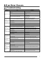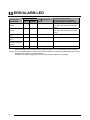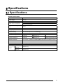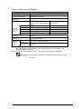
1
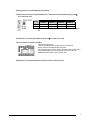
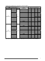
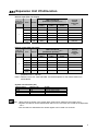
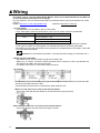
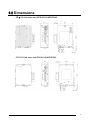
Safety Precautions
Observe the following notices to ensure personal safety or to prevent accidents.
To ensure that you use this product correctly, read this User’s Manual thoroughly before use.
Make sure that you fully understand the product and information on safety.
This manual uses two safety flags to indicate different levels of danger.
WARNING
If critical situations that could lead to user’s death or serious injury is assumed by
mishandling of the product.
-Always take precautions to ensure the overall safety of your system, so that the whole
system remains safe in the event of failure of this product or other external factor.
-Do not use this product in areas with inflammable gas. It could lead to an explosion.
-Exposing this product to excessive heat or open flames could cause damage to the lithium
battery or other electronic parts.
CAUTION
If critical situations that could lead to user’s injury or only property damage is
assumed by mishandling of the product.
-To prevent excessive exothermic heat or smoke generation, use this product at the values
less than the maximum of the characteristics and performance that are assured in these
specifications.
-Do not dismantle or remodel the product. It could cause excessive exothermic heat or smoke
generation.
-Do not touch the terminal while turning on electricity. It could lead to an electric shock.
-Use the external devices to function the emergency stop and interlock circuit.
-Connect the wires or connectors securely.
The loose connection could cause excessive exothermic heat or smoke generation.
-Do not allow foreign matters such as liquid, flammable materials, metals to go into the inside
of the product. It could cause excessive exothermic heat or smoke generation.
-Do not undertake construction (such as connection and disconnection) while the power
supply is on. It could lead to an electric shock.
Copyright / Trademarks
-This manual and its contents are copyrighted.
-You may not copy this manual, in whole or part, without written consent of Panasonic
Industrial Devices SUNX Co., Ltd.
-Windows is a registered trademark of Microsoft Corporation in the United States and other
countries.
-All other company names and product names are trademarks or registered trademarks of
their respective owners.
PLC_ORG
Table of Contents
Precautions before Using CC-link Slave Unit
1 Functions of CC-Link Slave Unit ................................................................................................................. 1
1.1 Unit Functions ...................................................................................................................................................................................................1
1.2 Unit Type .............................................................................................................................................................................................................1
1.3 Unit Connection ................................................................................................................................................................................................2
2 Part Names and Functions .......................................................................................................................... 3
2.1 Part Names and Functions ...........................................................................................................................................................................3
3 Allocation of Input/Output and Shared Memory........................................................................................ 6
3.1 FPΣCC-Link Slave Unit...............................................................................................................................................................................6
3.2 FP0 CC-Link Slave Unit............................................................................................................................................................................. 10
4 Wiring........................................................................................................................................................... 12
5 If an Error Occurs ....................................................................................................................................... 13
5.1 Troubleshooting.............................................................................................................................................................................................. 13
5.2 ERR/ALARM LED ......................................................................................................................................................................................... 14
6 Specifications.............................................................................................................................................. 15
6.1 Specifications.................................................................................................................................................................................................. 15
6.2 Dimensions ....................................................................................................................................................................................................... 17
Precautions before Using CC-Link Slave Unit
- Mounting plate
- Note that the types of mounting plates used for FPΣand FP0 are different.
Unit name (including CPU)
Mounting plate to be used
FPΣCC-Link slave unit
Slim type 30 FP0 mounting plate
AFP0811
FP0 CC-Link slave unit
Slim type FP0 mounting plate
AFP0803
- Installation of CC-Link slave unit
- Normally, any unit cannot be installed on the right side of the FP0 CC-Link slave unit.
- To assure the measurement accuracy, it is not recommended for any unit to be installed on the right side
of the FP0 thermocouple unit. When the FP0 CC-Link slave unit is used together with the FP0
thermocouple unit in a system, FP0 CC-Link slave unit can be on the right side of the FP0
thermocouple unit.
Reference: Measurement accuracy when the FP0 thermocouple unit is used together with the FP0
CC-Link slave unit in a system <1.3 Unit Connection>
- CC-Link Partner Association
1F Chusanren Bldg. 3-12-13 Shirakabe, Higashi-ku, Nagoya 461-0011, JAPAN
Phone: +81-52-936-6050, Fax: +81-52-936-6005
E-mail: [email protected]
HP: (English) : http://www.cc-link.org/eng/index.html
(Japanese): http://www.cc-link.org
1 Functions of CC-Link Slave Unit
1.1 Unit Functions
1. Data can be exchanged between the CC-Link master station and FP0/ FPΣslave station.
2. Communication speed: 157k to 10Mbit/s
3. Communication distance: 100 m to 1200m
4. Interface: RS485
5. I/O points: 16I/16O to 80I/80O (FP0 CC-Link slave unit)
: 16I/16O to 112I/112O (FPΣCC-Link slave unit)
1.2 Unit Type
- CC-Link slave unit
Name
Type
FPΣ
CC-Link slave unit
FPG-CCLS
FP0
CC-Link slave unit
FP0-CCLS
I/O points Note1
256 points Max.
(Input: 128)
(Output: 128)
192 points Max.
(Input: 96)
(Output: 96)
Number of data points
exchanged with CC-Link
Note3
master station
224 points Max.
(Input: 112, Output 112)
16-word data read/write (Max.)
32 points Max.
(Input: 16, Output 16)
4-word data read/write (Max.)
Product No.
AFPG7943
AFP07943
Note 1: Occupied number of I/O points in the FPΣ/0 expansion area
The number of the occupied I/O points varies depending on the switch setting
(for FPΣCC-Link slave unit) and the location of the expansion unit (for FP0
CC-Link slave unit).
Note 2: FP0 CC-Link slave unit does not have a connector for the next expansion unit.
One FP0 CC-Link slave unit should be installed on the extremely right in the
expansion position.
Note 3: All the data for the FP0 CC-Link slave unit are allocated to the I/O area.
Reference: <3 Allocation of Input/Output and Shared Memory>
1
1.3 Unit Connection
- Limitations in unit number and position
- FPΣCC-Link slave unit
Up to 4 expansion units (including other FPΣexpansion unit and FPΣhigh-performance unit) can be
installed.
- FP0 CC-Link slave unit
Up to 3 expansion units (including other FP0 expansion unit and FP0 high-performance unit) can be
installed. However, two or more FP0 CC-Link slave units cannot be installed in a system.
A unit cannot be installed on the right of the FP0 CC-Link slave unit, because the unit does not have the
expansion connector on its rihgt.
- When using the CC-Link slave unit with the FP0 thermocouple unit
In the FP0 thermocouple unit manual, it is not recommended for any unit to be installed on the right side
of the FP0 thermocouple unit to assure the measurement accuracy. However, the FP0 CC-Link slave
unit can be installed on the right of the FP0 thermocouple unit. In this case, the accuracy for the FP0
thermocouple unit is as shown in the table below.
Standard
When CC-Link
Thermocouple used
specifications
slave unit with the
K, J, T
0.8 ºC
2 ºC
3 ºC
2.5 ºC
2 ºC
6 ºC
5 ºC
4 ºC
thermocouple unit
0 to 99.9 ºC
100 to 299.9 ºC
300 to 1500 ºC
R
t
i
n
u
e
l
p
u
o
c
o
m
r
e
h
T
t
i
n
u
e
l
p
u
o
c
o
m
r
e
h
T
Can be used in accuracy as shown above
Can be used in the standard specifications
Reference: <FP0 Thermocouple Unit Technical Manual (ARCT1F366E)>
2
2 Part Names and Functions
2.1 Part Names and Functions
- FPΣCC-Link slave unit (FPG-CCLS) AFPG7943
- FP0 CC-Link slave unit (FP0-CCLS) AFP07943
①Operating monitor LEDs
②Number of occupied stations (Available only for FPΣCC-Link slave unit)
③Station No. selector switch
④Baud rate selection switch
⑤Transmission line (RS485) terminal block
⑥Fixing screw for a detachable terminal block
⑦Expansion connector occupied station No. selection switch
(Available only for FPΣCC-Link slave unit)
⑧Expansion connector (Available only for FPΣCC-Link slave unit)
⑨Power supply connector (24V DC)
⑩Expansion connector (Available only for FP0 CC-Link slave unit)
3
①Operating monitor LEDs
RUN
ERR
SD
RD
: Turns ON when communication is normal.
: Turns ON when a switch setting error has occurred.
Flashes when a switch setting is changed while the power is ON.
: Turns ON when data is being transmitted.
: Turns ON when data is being received.
ALARM : Turns ON when a hardware error has occurred.
Turns ON when a station No. setting error has occurred.
②Number of occupied stations (Available only for FPΣCC-Link slave unit)
1 to 4 LEDs: Number of occupied stations turns ON.
③Station No. selector switch
1 to 64: Station No.
0, and 65 to 99: Setting error
④Baud rate selection switch
SW. No.
156k
625k
1
OFF
ON
2
OFF
3
OFF
Baud rate
2.5M
5M
10M
OFF
ON
OFF
OFF
ON
ON
OFF
OFF
OFF
OFF
ON
OFF: Input data is cleared when communication halts. Note)
4
ON: Input data is held when communication halts. Note)
Note: FP0/FPΣ input data (output data from the master station)
⑤Transmission line (RS485) terminal block
Used for connecting the CC-Link cables.
The terminals SLD and FG are connected each other inside the
CC-Link unit.
4
⑥Fixing screw for a detachable terminal block
⑦Expansion connector occupied station No. selection switch (Available only for FPΣ
CC-Link slave unit)
SW. No.
Number of occupies station
1 station
2 stations
3 stations
4 stations
1
ON
OFF
ON
OFF
2
ON
ON
OFF
OFF
Note: These switch settings are available only for FPΣCC-Link slave
unit.
⑧Expansion connector (Available only for FPΣCC-Link slave unit)
⑨Power supply connector (24V DC)
・ Supply 24V DC power.
Use the provided power supply cable for connection.
・ Power used for the transmission line drive
・ FG terminals of the power supply connector and transmission
line terminal block are not connected in the CC-Link unit.
・ Isolated from the power for the control unit.
⑩Expansion connector (Available only for FP0 CC-Link slave unit)
5
3 Allocation of Input/Output and
Shared Memory
3.1 FPΣCC-Link Slave Unit
Communication with FPΣcontrol unit
In the CC-Link slave unit, CC-Link remote input/output is allocated to the I/O area, and CC-Link remote
register is allocated to the shared memory area. The number of remote words varies depending on the
CC-Link station No. settings (1 to 4 stations).
Additionally, I/O allocation and shared memory slot No. depend on the location to be installed.
・ Remote input/output points per station: input 32 points, output 32 points
・ Remote register per station: 4 words for read, 4 words for write
Reference:<3.1.1Expansion Unit I/O Allocation>
Remote input/output: Automatic update by the I/O refresh instruction
Remote register: Executed by the shared memory READ/WRITE instructions (F150 and F151)
Slot No.
1
2
3
4
FPΣexpansion unit No. Note)
Shared memory slot No.
0
1
2
3
Note: The expansion units closer to the control unit have the lower
expansion unit number. (Expansion unit 1, 2, 3 and 4 in the
diagram on the left)
6
3.1.1
Expansion Unit I/O Allocation
Remote input (FPΣside output)
No. of
occupied
stations
Note 2
Area
User
area
System
area
User
area
System
area
User
area
System
area
User
area
System
area
1
2
3
4
FPΣCC-Link I/O (installation position)
Expansion
Expansion
Expansion
Expansion
unit 1
unit 2
unit 3
unit 4
CC-Link
master
remote I/O
16
Y100-Y10F
Y180-Y18F
Y260-Y26F
Y340-Y34F
RX00-RX0F
16
Y110-Y11F
Y190-Y19F
Y270-Y27F
Y350-Y35F
RX10-RX1F
48
Y100-Y12F
Y180-Y20F
Y260-Y28F
Y340-Y36F
RX00-RX2F
16
Y130-Y13F
Y210-Y21F
Y290-Y29F
Y370-Y37F
RX30-RX3F
80
Y100-Y14F
Y180-Y22F
Y260-Y30F
Y340-Y38F
RX00-RX4F
16
Y150-Y15F
Y230-Y23F
Y310-Y31F
Y390-Y39F
RX50-RX5F
112
Y100-Y16F
Y180-Y24F
Y260-Y32F
Y340-Y40F
RX00-RX6F
16
Y170-Y17F
Y250-Y25F
Y330-Y33F
Y410-Y41F
RX70-RX7F
Points
Remote output (FPΣside input)
No. of
occupied
stations
2
3
4
CC-Link
master
remote I/O
16
X100-X10F
X180-X18F
X260-X26F
X340-X34F
RY00-RY0F
16
X110-X11F
X190-X19F
X270-X27F
X350-X35F
RY10-RY1F
48
X100-X12F
X180-X20F
X260-X28F
X340-X36F
RY00-RY2F
16
X130-X13F
X210-X21F
X290-X29F
X370-X37F
RY30-RY3F
80
X100-X14F
X180-X22F
X260-X30F
X340-X38F
RY00-RY4F
16
X150-X15F
X230-X23F
X310-X31F
X390-X39F
RY50-RY5F
112
X100-X16F
X180-X24F
X260-X32F
X340-X40F
RY00-RY6F
16
X170-X17F
X250-X25F
X330-X33F
X410-X41F
RY70-RY7F
Note 2
Area
User
area
System
area
User
area
System
area
User
area
System
area
User
area
System
area
1
FPΣCC-Link I/O (installation position)
Expansion
Expansion
Expansion
Expansion
unit 1
unit 2
unit 3
unit 4
Points
Note 3
Note 1: The expansion units closer to the control unit have the lower expansion unit number.
(Expansion unit 1, 2, 3 and 4)
Note 2: Remote I/O RX and RY are the descriptions for the master station from MITSUBISHI.
System area allocation (bit)
FPΣCC-Link Note
Y_0-_A
Y_B
Y_C-_F
X_0-_F
Note: The value marked with “_” varies
Master station
RX*0-*A
RX*B
RX*C-*F
RY*0-*F
Signal
Not available
Remote station Ready
Not available
Not available
depending on the installation
position of the unit.
For details, refer to the allocation tables above.
Note: System areas cannot be used in the user program.
7
3.1.2 Shared Memory Allocation
Slot No.
3
4
FPΣexpansion unit No. Note)
1
2
2
3
Shared memory slot No.
0
1
Note: The expansion units closer to the control unit have the lower
expansion unit number. (Expansion unit 1, 2, 3 and 4 in the
diagram on the left)
Error information and status (All the data cannot be updated.)
Shared memory
address (word unit:
decimal number)
Item
00 to 16
System/reserved area
17
Setting information
(Updated when
communication is
established)
bit 4, 5, 8, 9
(Other bit: 0)
Station No.
x10
Station No. x 100 :0 to 9
bit 4 to 7
Station No.
x101
Station No. x 101 :0 to 6
bit 8 to B
Baud rate
bit 5
Station No. switch
change
Baud rate switch
change
bit 8
CRC error
bit 9
Overtime
bit 4
19
20
Status information
bit 0, 1
(Other bit: 0)
8
0
0 to 4
0 to 3
0: Normal
1: Error
0: Normal
1: Error
0: Normal
1: Error
0: Normal
1: Error
Reserved area
bit 0
bit 1
21 to 31
Not available
bit 0 to 3
bit C~F Occupied station No.
18
Error information
Description
Master CPU
Operation mode
flag
Master CPU status
flag
Setting information
Baud rate: 0
156kbit/s
1
625kbit/s
2
2.5Mbit/s
3
5Mbit/s
4
10Mbit/s
Occupied station No.:
0 (1 station) to 3 (4 stations)
Station No. switch is changed
when power is ON.
Baud rate switch is changed
when power is ON.
Not available
0: STOP
1: RUN
0: Normal
1: Error
Not available
Remote device (Addresses are indicated in a decimal number.)
FPΣshared memory address
Instruction
Word address
F150
Master→FPΣ
32
33
34
35
36
37
38
39
40
41
42
43
44
45
46
47
F151
Master←FPΣ
48
49
50
51
52
53
54
55
56
57
58
59
60
61
62
63
I/O
Input
Output
Master station remote
register
(Hexadecimal)
Number of occupied station
2
3
4
RWw0
RWw1
RWw2
RWw3
RWw4
RWw5
RWw6
RWw7
RWw8
RWw9
RWwA
RWwB
RWwC
RWwD
RWwE
RWwF
Available
Available
Available
Available
Available
Available
Available
Available
Available
Available
Available
Available
Available
Available
Available
Available
-
-
-
-
-
-
-
-
-
-
-
-
Available
Available
Available
Available
Available
Available
Available
Available
Available
Available
Available
Available
-
-
-
-
-
-
-
-
Available
Available
Available
Available
Available
Available
Available
Available
-
-
-
-
Available
RWr0
RWr1
RWr2
RWr3
RWr4
RWr5
RWr6
RWr7
RWr8
RWr9
RWrA
RWrB
RWrC
RWrD
RWrE
RWrF
Available
Available
Available
Available
Available
Available
Available
Available
Available
Available
Available
Available
Available
Available
Available
Available
-
-
-
-
-
-
-
-
-
-
-
-
Available
Available
Available
Available
Available
Available
Available
Available
Available
Available
Available
Available
-
-
-
-
-
-
-
-
Available
Available
Available
Available
Available
Available
Available
Available
-
-
-
-
Available
Available
Available
Available
Available
Available
Available
Note: Remote register RWw and RWr are the descriptions for the master station from MITSUBISHI.
9
3.2 FP0 CC-Link Slave Unit
Communication with FP0 control unit
Only one FP0 CC-Link slave unit can be installed on the extreme right in the expansion unit(s).
In the FP0 CC-Link slave unit;
・CC-Link remote I/O and remote register are allocated to the expansion unit I/O 1st word and 2nd word (or
later), respectively. The number of the word of the remote register varies depending on the expansion
unit’s installation position.
・Number of remote I/O points: 16 (input points), 16 (output points)
・Remote register: Max. 4 words for read and write each
Reference:<3.2.1Expansion unit I/O allocation>
When 5 words can be used:
Remote I/O : 1 word (input)/1 word (output)
Remote register: 4 words (read)/ 4 words (write)
When 4 words can be used:
Remote I/O : 1 word (input)/1 word (output)
Remote register: 3 words (read)/ 3 words (write)
When 2 words can be used:
Remote I/O : 1 word (input)/1 word (output)
Remote register: 1 word (read)/ 1 word (write)
Note: - In the FP0 CC-Link slave unit, shared memory cannot be used.
- When an expansion unit is newly added after the I/O allocation is set, the I/O allocation is
concurrently changed.
10
3.2.1 Expansion Unit I/O Allocation
Remote input (FP0 side output)
No. of
occupied
stations
1
Area
FP0 CC-Link I/O
(installation position) Note1
Points
Expansion
unit 2
Y40-4F
Expansion
unit 3
Y60-6F
CC-Link
master
remote I/O
I/O
16
Expansion
unit 1
Y20-2F
Register
16
WY3
WY5
WY7
RWr 0
Register
16
WY4
WY6
-
RWr 1
Register
16
WY5
WY7
-
RWr 2
Register
16
WY6
-
-
RWr 3
System
area
16
WY7
-
-
RX10-1F
Note2
RX00-0F
Remote output (FP0 side input)
No. of
occupied
stations
1
Area
FP0 CC-Link I/O
(installation position) Note1
Points
Expansion
unit 2
X40-4F
Expansion
unit 3
X60-6F
CC-Link
master
remote I/O
I/O
16
Expansion
unit 1
X20-2F
Register
16
WX3
WX5
WX7
RWw 0
Register
16
WX4
WX6
-
RWw 1
Register
16
WX5
WX7
-
RWw 2
Register
16
WX6
-
-
RWw 3
System
area
16
WX7
-
-
RY10-1F
Note2
RY00-0F
Note 1: The expansion units closer to the control unit have the lower expansion unit number.
(Expansion unit 1, 2 and 3)
Note 2: Remote I/O RX, RY, RWr and RWw are the descriptions for the master station from
MITSUBISHI.
System area allocation (bit)
Master station
RX*0-*A
RX*B
RX*C-*F
RY*0-*F
FP0 CC-Link
Y70-7A
Y7B
Y7C-7F
X70-7F
Signal
Not available
Remote station Ready
Not available
Not available
Note: 1.Data cannot be written in the system area. (Data can be read from the system area.)
2.System area above can be referred when the FP0 CC-Link slave unit is used as the Expansion
unit 1.
3.I/O area which is allocated to the remote register can be used in a word unit.
11
4 Wiring
For details, refer to “CC-Link Cable Wiring Manual” which can be downloaded from the Web site
of CC-Link Partner Association free of charge.
For your reference: CC-Link Partner Association (“Precautions before Using CC-link Slave Unit” of this
manual.)
English: http://www.cc-link.org/eng/index.html
Japanese: http://www.cc-link.org
- CC-Link cables
- Use dedicated CC-Link cables in the CC-Link system.
- If any other cable is used, the performance of the CC-Link system cannot be guaranteed.
Terminal resistor
Cable
Dedicated CC-Link cables
(for CC-Link Ver. 1.10)
110Ω
Dedicated CC-Link cables
130Ω
Dedicated CC-Link high-performance cable
- Make sure to use only one type of cables (CC-Link cables or CC-Link high-performance cables).
If both types of cables are used together, normal data transmission cannot be guaranteed.
- For details concerning the specifications and connection for the dedicated CC-Link cables, contact the
CC-Link Partner Association.
Reference:CC-Link Partner Association <“Precautions before Using CC-Link Slave Unit” >
- Wiring with CC-Link cables
- The cables can be connected without regard to the station No..
- Make sure to connect a terminal resistor (provided as an accessory of the unit) between the
terminals DA and DB in the units at both ends.
- For details, refer to the CC-Link master station’s manual.
- Connection
The shielded CC-link cable should go through the terminals SLD and FG in each unit, and both ends
should be grounded (less than 100Ω).
The terminals SLD and FG are connected each other inside the unit.
- When CC-Link slave unit is used as the terminal station:
Secure the cable and terminal resistor to the terminal block using the screws.
- When CC-Link slave unit is not used as the terminal station:
Secure the cables to the terminal block using the screws.
12
5 If an Error Occurs
5.1 Troubleshooting
Error
Item
Are any cables broken?
Confirmation
Check the cable status visually or by the line test.
Are terminal resistors properly connected to the stations at the Connect terminal resistors (provided for the master station) to the
both ends?
stations at the both ends.
Entire system data link
error
Has an error occurred in the control unit of the master unit?
Check the error code for the master station and take the proper
measure.
Are parameters set for the master station?
Check the contents of the parameters.
Has an error occurred in the master station?
Does the CC-Link slave unit participate in the data link?
Check the followings:
・ Parameter status in the host station
・ Switch setting status
・ Installation status
・ Flashing of “ERR” LED in the master station
Check the followings:
・ LED indication in the CC-Link slave unit
・ Communication status in other stations of the master station
Master side:
Is the data read from the correct address of the master station
Check the sequence program in the master station.
Remote input (RX) from
remote input RX?
the CC-Link slave unit
cannot be received.
Is the data written in the correct I/O number allocated to the
Check the sequence program in the FP0/FPΣcontrol unit .
CC-Link slave unit?
(Check: Output Y on the
Check the contents of the parameters in the master station.
CC-Link slave unit side) Is the station specified as reserved one?
Does the station No. overlap?
Check the station No.
Do the connection and setting comply with the specifications for
Check the specifications for the master station.
the master station?
Check the followings:
Does the CC-Link slave unit participate in the data link?
・ LED indication in the CC-Link slave unit
・ Communication status in other stations of the master station
Is the refresh instruction output turned ON in the master station? Check the sequence program in the master station.
Master side:
Remote output (RY)
Is the data written in the correct address of the master station
from the CC-Link slave
remote output RY?
unit cannot be turned
Is the data read from the correct I/O number allocated to the
ON/OFF.
CC-Link slave unit?
(Check: Input X on the
Is the station specified as reserved one?
CC-Link slave unit side)
Does the station No. overlap?
Do the connection and setting comply with the specifications for
the master station?
Master side:
Remote register (RWr)
data from the CC-Link
slave unit cannot be
received.
(Check: Output Y on
FP0 CC-Link slave unit
side,
Shared memory
address Nos. 48 to 63
on FPΣCC-Link slave
unit side)
Does the CC-Link slave unit participate in the data link?
Check the sequence program in the master station.
Check the sequence program in the FP0/FPΣcontrol unit.
Check the contents of the parameters in the master station.
Check the station No.
Check the specifications for the master station.
Check the followings:
・ LED indication in the CC-Link slave unit
・ Communication status in other stations of the master station
Is the data read from the correct address of the master station
Check the sequence program in the master station.
remote register RWr?
Is the data written in the correct I/O number (FP0 CC-Link slave
unit) and shared memory address (FPΣCC-Link slave unit) Check the sequence program in the FP0/FPΣcontrol unit.
allocated to the CC-Link slave unit?
Is the station specified as reserved one?
Check the contents of the parameters in the master station.
Does the station No. overlap?
Check the station No.
Do the connection and setting comply with the specifications for
Check the specifications for the master station.
the master station?
Check the followings:
Does the CC-Link slave unit participate in the data link?
・ LED indication in the CC-Link slave unit
Master side:
・ Communication status in other stations of the master station
Remote register (RWw)
from the CC-Link slave Is the data written in the correct address of the master station
Check the sequence program in the master station.
remote register RWw?
unit cannot be turned
ON/OFF.
Is the data read from the correct I/O number (FP0 CC-Link slave
unit) and shared memory address (FPΣCC-Link slave unit) Check the sequence program in the FP0/FPΣcontrol unit.
(Check: Input X on FP0 allocated to the CC-Link slave unit?
CC-Link slave unit side,
Shared memory
Is the station specified as reserved one?
Check the contents of the parameters in the master station.
address Nos. 32 to 47
on FPΣCC-Link slave Does the station No. overlap?
Check the station No.
unit side)
Do the connection and setting comply with the specifications for
Check the specifications for the master station.
the master station?
Note: For details, refer to the CC-Link master station manual.
13
5.2 ERR/ALARM LED
Station No. setting
change
Flashing
OFF
Normal
Baud rate setting
change
Flashing
OFF
Normal
ON
ON
Normal
CC-Link slave unit status
(I/O point, station No., baud rate,
occupied number of stations, etc)
Operation is not affected.
Error flag can be checked in the master
station.
Operation is not affected.
Error flag can be checked in the master
station.
Operation cannot be executed.
ON
ON
Normal
Operation cannot be executed.
OFF
ON
I/O verification error
Operation cannot be executed.
-
ON
Extra unit out of control
Operation cannot be executed.
Cause of the
ERR/ALARM
Station No. setting
error
Baud rate setting
error
Setting change of
occupied number of
stations
Hardware error
LED
ERR
ALARM
FP0/∑ control unit
status
Note 1: “Extra unit out of control” cannot be detected in the FP0 CC-Link slave unit.
When a hardware error occurs in the FP0 CC-Link slave unit, “I/O verification error” is issued.
Note 2: As one occupied station is used for FP0 CC-Link slave unit, FP0 CC-Link slave unit has no LEDs
indicating the number of occupied stations.
Therefore, the setting change error of occupied number of stations is not issued.
14
6 Specifications
6.1 Specifications
- General specifications
Item
Description
Rated voltage
24V DC
Operating voltage range
21.6 to 26.4V DC
CC-Link unit: 40 mA or less/24V DC
Increase amount in the control unit when expansion units are added:
40 mA or less/24V DC
Rated current consumption
Allowed momentary power off
time
10 ms
Ambient temperature
0 to 55℃
Storage temperature
-20 to +70℃
Ambient humidity
30 to 85 %RH (at 25°C, non condensing)
Storage humidity
30 to 85 %RH (at 25°C, non condensing)
Between RS 485
Power supply terminal
terminals
Station No.
Between RS 485
Power supply terminal
terminals
Station No.
Breakdown voltage
Insulation resistance
500V AC for 1 min.
100 MΩ or more
(measured with 500V DC)
Vibration resistance
10 to 55 Hz, 1cycle/1min.: double amplitude of 0.75 mm on 3 axes for 10 min.
Shock resistance
Shock of 98 m/s2 or more, 4 times on 3 axes
Noise immunity
1000 Vp-p with pulse widths 50 ns and 1µs (based on in-house measurement)
Operating condition
Free from corrosive gases and excessive dust
Weight
FPΣ CC-Link
slave unit
FP0 CC-Link
slave unit
Approx. 90 g
Approx. 80 g
15
- CC-Link communication specifications
Item
Description
Version
CC-Link Ver. 1.10
Communication method
Broadcast polling method
Communication speed
(Baud rate)
10Mbit/s, 5Mbit/s, 2.5Mbit/s, 625kbit/s, 156kbit/s
Maximum
total cable
length Note1)
10Mbit/s
5Mbit/s
Ver.
1.10
CC-Link
cable CC-Link high-performace
cable
100m
160m
100m
150m
2.5Mbit/s
400m
200m
625kbit/s
900m
600m
156kbit/s
1200m
1200m
Interface
RS485
Station type
Remote device station
Number of
occupied
points
FPΣ CC-Link
slave unit
FP0 CC-Link
slave unit
CC-Link cable
1 to 4 stations (switch changeover)
1 station
Note 1: Length of the multi-drop connected cables at both ends
The cable length has restrictions in communication speed, CC-Link version, and
dedicated cables to be used.
Note 2: For details concerning the CC-Link, refer to the CC-Link Partner Association.
Reference: CC-Link Partner Association <Precautions before Using CC-Link
Slave Unit>
16
6.2 Dimensions
- FPΣ CC-Link slave unit (FPG-CCLS) AFPG7943
- FP0 CC-Link slave unit (FP0-CCLS) AFPO7943
17
18
Record of changes
Manual No.
Date
Desceiption of changes
ARCT1F380E
APR.2003
First edition
ARCT1F380E-1
JUL.2005
2nd edition
ARCT1F380E-2
NOV.2008
3rd edition
- Change in Corporate name
ARCT1F380E-3
AUG.2011
4th edition
- Change in Corporate name
ARCT1F380E-4
JUL.2013
5th edition
- Change in Corporate name