1
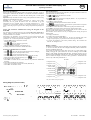
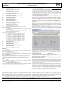
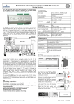
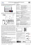
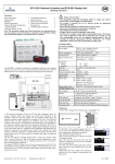
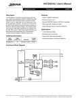
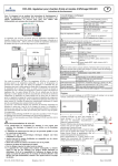
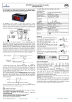
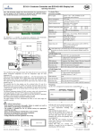
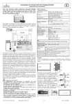
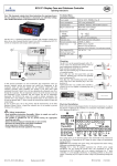
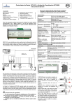
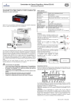
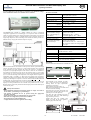
EC3-652 Rack Controller and ECD-000 Display Unit
GB
Operating Instructions
Note: This document contains short form instructions for experienced users.
Use last column in List of Parameters to document your individual settlings.
More detailed information can be found in the User Manual.
Technical Data
EC3 Series Controller
Power supply
Power consumption
20VA max.
Communication
Plug-in connector size
TCP/IP Ethernet 10MBit/s
Removable screw terminals
wire size 0.14 … 1.5 mm2
-20 … +65°C
0 … +60°C
0…80% r.h. non condensing
IP20
24VDC, 4...20mA
NTC 86kΩ @ 25°C, -40 … +180°C
Applies if C4= 2 & F5= 2
1 MΩ @ 25°C, +50 … +150°C
NTC 10 kΩ @ 25°C, -50 … +50°C
24VAC/DC or 230VAC
Inductive (AC15) 250V/2A
Resistive (AC1) 250V/8A
Semi-conductor switch, 24 … 230 VAC, 2A
The coil must be rated for the voltage applied
to the input
Temperature
The EC3-652 rack controller is a digital controller for racks in commercial
refrigeration applications for controlling up to 8 compressors with conventional
on/off step control working on a common suction line. Alternatively, the controller
may be configured to control a Copeland Digital Scroll compressor and up to 7
single stage compressors. The control target is to maintain the suction pressure at a
defined value by varying the available compressor capacity.
24VAC ±10%; 0.5A 50/60Hz; Class II
6.3mm spade earth connector
storage
operating
Humidity
Protection class
Pressure transmitter inputs
Temp 1: for Digital Scroll
(Dynamic based on settings)
Temp. 1 input discharge (1)
Temp. ambient
Digital Inputs
Compressor output relays
(8x) + General alarm output
Digital scroll output
!
ECD-000 Display Unit
Power Supply
From EC3-652 via connecting cable
Display
2½-digit red LED with decimal point
reversible between °C and °F
LED indicators
Controller 1, Controller 2, p bar, Alarm, IR status
Temp & Humidity
Identical to EC3-652 specifications above
Protection class
Connecting cable
IP65 (front protection with gasket)
ECC-N10 (1m), ECC-N30 (3m), ECC-N50 (5m) or
CAT5 cable with RJ45 connectors
Mounting
The EC3-652 can be mounted onto a standard DIN rail.
For the measurement of the common suction pressure and the optional discharge
pressure, two PT4 pressure sensors (2, 3) with 4–20mA interface can be connected
to the controller. The rack controller has eight relay outputs to command the
compressors (9). Eight digital inputs for 24V AC/DC or 230V AC are available for
the compressor serial alarms (4) plus one for low pressure alarm (5), one for high
pressure alarm (6), one for oil level alarm (7) and one for refrigerant level alarm
(8). To control the discharge end temperature of the Digital Scroll compressor a
temperature input is available (1). When used, the Digital Scroll Compressor
operates as the base load compressor with capacity modulation being achieved by
temporarily unloading the compressors scroll sets with the Pulse Width Modulated
(PWM) signal (10) which controls the compressor unloading valve.
The optional ECD-000 Display Unit can be connected to the EC3-652 for local
display of control parameters and for controller setup without the use of a PC.
Because the EC3-652 is fully functional without display unit the ECD-000 may be
removed at any time.
!
•
•
•
•
•
•
Safety instructions:
Read installation instructions thoroughly. Failure to comply can result in
device failure, system damage or personal injury.
The product is intended for use by persons having the appropriate
knowledge and skills.
Ensure electrical ratings per technical data are not exceeded.
Disconnect all voltages from system before installation.
Keep temperatures within nominal limits.
Comply with local electrical regulations when wiring
EC3-652_65147_EN_R01.doc
72
EC3
104
250
62
The ECD-000 can be mounted in panels
with a 71x29 mm cutout. See dimensional
drawing below for space requirements
including rear connectors.
Push controller into panel cutout. (1)
Make sure that mounting lugs are flush with
outside of controller housing
Insert allen key into front panel holes and
turn clockwise. Mounting lugs will turn and
gradually move towards panel (2)
Turn allen key until mounting lug barely
touches panel. Then move other mounting
lug to the same position (3)
Tighten both sides very carefully until
display is secured. Do not over tighten as
mounting lugs will break easily.
1/4
PCN: 865027
06.03.2009
EC3-652 Rack Controller and ECD-000 Display Unit
GB
Operating Instructions
Electrical Installation
Special Functions:
Refer to the electrical wiring diagram (below) for electrical connections. A copy of
this diagram is labeled on the controller. Use connection wires/cables suitable for
90°C operation (EN 60730-1). Ground the metal housing with a 6.3mm spade
connector.
Important: Keep controller and sensor wiring well separated from mains wiring.
Minimum recommended distance 30mm..
Warning: Use a class II category transformer for 24VAC power supply
(EN 60742). Do not ground the 24VAC lines. We recommend to use one
transformer per EC3 controller and to use separate transformers for 3rd party
controllers, to avoid possible interference or grounding problems in the power
supply. Connecting any EC3 inputs to mains voltage will permanently damage the
EC3.
The Clear Alarm function has been replaced by the Special Functions mode. The
Special Functions can be activated by:
• Press
and together for more than 5 seconds.
A flashing 0 is displayed.
• Press
or
until the password is displayed (default = 12). If password was
changed, select the new password.
• Press SEL to confirm password
A 0 is displayed and the Special Function mode is activated.
• Press
or
to select the function. The number of special functions is dynamic
and controller dependent. See list below.
• Press SEL to activate the function without leaving the special function mode.
• Press PRG to activate the function and leave the special function mode.
Most of the Special Functions work in a toggle mode, the first call activates the
function, and the second call deactivates the function.
The indication of the function can only be displayed after exiting the special
function mode.
• 0: Display test function
• 1: Displays the current TCP/IP address
• 2: Set the controller's TCP/IP address to 192.168.1.101 (default value). This
change is only temporary. A power down will reset the previous address.
• 3: Resets all parameters to the factory default setting. The controller will
indicate “oF” during the reset.
Setup and Parameter Modification Using the Keypad of the
ECD-000
For convenience, an infrared receiver for the optional IR remote control unit is
build-in, enabling quick and easy modification of the system parameters when a
computer interface is not available.
Alternatively, the parameters can be accessed via the 4-button keypad. The
configuration parameters are protected by a numerical password. The default
password is “12”. To select the parameter configuration:
• Press the PRG button for more than 5 seconds
A flashing 0 is displayed
• Press
or until 12 is displayed; (password)
• Press SEL to confirm password
The first modifiable parameter code is displayed (/1).
To modify parameters see Parameters modification below.
Parameter Modification: Procedure
Press or to show the code of the parameter that has to be changed;
Press SEL to display the selected parameter value;
• Press
or to increase or decrease the value;
• Press SEL to temporarily confirm the new value and display its code;
• Repeat the procedure from the beginning "press
or to show..."
To exit and save the new settings:
• Press PRG to confirm the new values and exit the parameters modification
procedure.
To exit without modifying any parameter:
• Do not press any button for at least 60 seconds (TIME OUT).
• Press “ESC” on IR remote control.
•
•
Display of Data:
The data to be permanently shown on the display can be selected by the user (parameter
/1). In case of an alarm, the alarm code is displayed alternately with the selected data.
The user can inhibit the alarm code.
It is possible to temporarily display these values. This is a useful feature when
initially setting-up the system without the aid of the WebPages. Press the SEL
button to scroll through all possible displayable data.. The display will show for one
second the numerical identifier of the data (see /1 parameter) and then the selected data.
After two minutes the display will return to the by parameter /1 selected data. This
action is only valid when parameter H2 = 3
IR Status
Compressor 8 On
Compressor 1 On
Compressor 7 On
Compressor 2 On
Controller 1 LED
Service LED*
Controller 2 LED
Pressure LED
Alarm LED
Compressor 6 On
Compressor 5 On
Compressor 3 On
Compressor 4 On
* only active when service pin is pressed
Wiring Diagram (controller label)
EC3-652_65147_EN_R01.doc
2/4
PCN: 865027
06.03.2009
EC3-652 Rack Controller and ECD-000 Display Unit
GB
Operating Instructions
List Of Parameters
/ DISPLAY PARAMETERS
Min Max Unit
Def. Custom
/1 Value to show
0
5
0
0 = Compressors states
1 = Suction pressure (bar)
2 = Suction temperature (°C) calculated from suction pressure
3 = Condensing pressure (bar)
4 = Condensing temperature (°C) calculated from discharge pressure
5 = Digital Scroll capacity (%)
P SET-POINT PARAMETERS
P0 Suction pressure set point
-1
50
bar
3.0
P1 Suction band
0
50
bar
2.0
P3 Fast recovery from low pressure
-9.9 50
bar
-9.9
P4 Suction shift (0=disabled, 1=enabled)
0
1
0
P5 Suction shift max
0
3.0
bar
3.0
P8 High discharge pressure recovery
-9.9 50
bar
50.0
P9 Discharge recovery step
0
5.0
bar
1.0
t TIME PARAMETERS
t0 Integration time
30
99 10 sec* 60
t1 Time delay before adding capacity
0
99 10 sec*
6
t2 Time delay before removing capacity
0
99 10 sec*
0
t3 Compressor min on time
0
99 10 sec*
6
t4 Compressor min off time
0
99 10 sec*
6
t5 Maximum compressor switching
0
199
1/hr
0
(0=number of switching unrestricted)
A ALARM-PARAMETERS
A0 Alarm delay LP
0
99 10 sec*
0
A1 Alarm delay HP
0
99 10 sec*
0
A2 Suction alarm min. limit
-1.0 50
bar
1.0
A3 Suction alarm max. limit
-1.0 50
bar
6.0
A4 Alarm delay suction min. limit
0
99 10 sec*
0
A5 Alarm delay suction max. limit
0
99 10 sec*
0
A6 Maximum discharge temperature
50 150
°C
130
A7 Maximum discharge temperaturedelay 0
99 10 sec*
3
A8 Alarm delay serial alarm compr.
0
99 10 sec*
0
A9 Compressor service interval
0
99 10, 000
0
c APPLICATION PARAMETERS
Min Max
c1 Number of compressors
1
8
c3 Compr. control mode (0 = P mode,
0
3
1 = PI mode, 2 = dead band mode
3 = binary mode)
c4 Compressor 1 control mode:
0
1
0 = in standard control loop
1 = act as base load compressor
2 = act as modulating capacity; single stage;
c5 Compressor rotation
0
1
0 = FILO logic (First In, Last Out)
1 = FIFO logic (First In, First Out)
c6 Sensor fail
0
8
(number of compressors in case of
sensor failure)
h0 Condensing pressure
0
1
0 = not available; 1 = available
r
r0
r1
r2
r3
r4
r5
r6
F
F2
F3
F5
MODULATING PARAMETERS
Compressor min. capacity
Compressor max. capacity
Analogue output mode for Comp. 1
0 or 1= 0 - 10V ; 2 = PWM (digital)
F6 PWM cycle time
hr**
u STEP ENABLE PARAMETERS
u0 Comp service interval reset
0 = do nothing
1 = reset operating time compressor 1
2 = reset operating time compressor 2
3 = reset operating time compressor 3
4 = reset operating time compressor 4
5 = reset operating time compressor 5
6 = reset operating time compressor 6
7 = reset operating time compressor 7
8 = reset operating time compressor 8
9 = reset operating time all compressors
u1 Compressor enable 1
(0=disable, 1=enable)
u2 Compressor enable 2 ( - " - )
u3 Compressor enable 3 ( - " - )
u4 Compressor enable 4 ( - " - )
u5 Compressor enable 5 ( - " - )
u6 Compressor enable 6 ( - " - )
u7 Compressor enable 7 ( - " - )
u8 Compressor enable 8 ( - " - )
0
9
-
0
0
1
flag
1
0
0
0
0
0
0
0
1
1
1
1
1
1
1
flag
flag
flag
flag
flag
flag
flag
1
1
1
1
1
1
1
SENSOR PARAMETERS
Suction sensor 0%
Suction sensor 100%
Suction sensor offset
Discharge sensor 0%
Discharge sensor 100%
Discharge sensor offset
Refrigerant
0 = R 22
3 = R 404A
1 = R 134a
4 = R 407C
2 = R 507
5 = R 410A
6 = R 124
7 = R 744
H OTHER PARAMETERS
H2 ECD Display access
0 = all disabled
(Caution, access to controller only
via TCP/IP network possible)
1 = Keyboard enabled
2 = IR remote control enabled
3 = Keyboard and IR remote control
enabled
H3 IR access code
H5 Password
Unit
-
Def. Custom
8
2
flag
2
flag
1
-
0
flag
1
-1.0
-1.0
-1.0
-1.0
-1.0
-1.0
0
50
50
1.0
50
50
1.0
7
bar
bar
bar
bar
bar
bar
-
-0.8
7
0.0
0.0
30
0.0
3
10
10
0
100
100
2
%
%
-
10
100
2
10
20
sec
10
0
3
-
3
0
0
199
199
-
0
12
* These values have a resolution of 10 sec, on the local display. Example a value 2
means 20 sec.
** These values have a resolution of 10,000 hours, on the local display. Example a
value 2 means 2.000 hours.
EC3-652_65147_EN_R01.doc
3/4
PCN: 865027
06.03.2009
EC3-652 Rack Controller and ECD-000 Display Unit
GB
Operating Instructions
Alarm Codes
Visualising Data: WebPages
HP
A TCP/IP Controller-Readme file is available on the www.emersonclimate.eu
website to provide detailed information about TCP/IP Ethernet connectivity. Please refer
to this file if you need information beyond the contents of this instruction sheet.
The EC3-652 has a TCP/IP Ethernet communication interface enabling the
controller to be directly connected to a PC or network via the standard Ethernet
port. The EC3-652 controller has embedded WebPages to enable the user to easily
visualise the parameter lists using real text labels.
No special software or hardware is required.
Connect the EC3-652 using the optional ECX-N60 cable assembly to a network or
hub that enables the controller to receive a dynamic TCP/IP address. If a DHCP
server is not available, the controller can be connected to a computer using a
crossover cable plugged directly into the Ethernet port. In this case, the TCP/IP
address of the computer must be manually modified to be compatible with the
default address of the controller. Refer to the TCP/IP Controller-Readme file for
more details.
Open the Internet browser program on the computer and enter the default TCP/IP
address of the controller into the address line of the Internet browser:
192.168.1.101 or the dynamic address from the DHCP server. Refer to the TCP/IP
Controller-Readme file if a specific port is required.
After a few moments, the default monitoring page should be displayed. If the
browser does not open the default page or display active data, the user should
check the Internet browser “Option” configuration. Refer to the TCP/IP
Controller-Readme file.
General alarm HP
High pressure signal from digital input
LP
General alarm LP
Low pressure signal from digital input
hP
Limit violation suction side
Suction pressure higher than the maximum limit
lP
Limit violation suction side
Suction pressure lower than the minimum limit
EP
Sensor failure suction side
Suction pressure sensor failure
Ed
Sensor failure condenser
Discharge pressure sensor failure
Fr
Fast recovery suction low
Fast recovery from low suction pressure
hr
Fast recovery condensing
High discharge pressure recovery
d1
Discharge temperature alarm 1
Discharge end temperature from compressor 1 is to high
E1 to E8 Serial alarm
E1: Digital input associated with compressor 1 has changed into alarm
state (safety chain)
E2, E3 … E8: Digital input associated with compressor 2, 3 … 8 has
changed into alarm state (safety chain)
n1 to n8 Service alarm compressor
n1: Compressor 1 operating time higher than run limit
n2: Compressor 2 operating time higher than run limit
n3: Compressor 3 operating time higher than run limit
n4: Compressor 4 operating time higher than run limit
n5: Compressor 5 operating time higher than run limit
n6: Compressor 6 operating time higher than run limit
n7: Compressor 7 operating time higher than run limit
n8: Compressor 8 operating time higher than run limit
oL
Oil receiver level alarm
Oil level detection from digital input
rL
Refrigerant level alarm
Refrigerant level detection from digital input
Er
Data error - out of range
Data send to the display is out of range
Messages
--No data
The display will show an “---” at node start up, when no data is send to the display
or when the display is disabled.
In
Configuration data initialization
The display will show an “In” when the configuration data are initialized with the
factory default values.
Id
Wink request received
The display will show a flashing “Id” when the wink request was received. The
node will receive the flashing “Id” will be shown on the display until the service
button will be pressed, or a 30 min delay timer will expire or a second wink
request.
oF
Offline
The node is offline: no application is running. This is the result of a network
management command an will happen
- -- --Controller disabled, waiting for restart
After a major change of the configuration parameter, the rack controller is disabled
for 20 seconds. After this delay the controller restart automatically.
The Monitoring and Alarm WebPages are read only and therefore it is not
necessary to enter a username or password. A username and password will be
requested upon the initial request to any of the other WebPages. The factory
default settings are :
Username : EmersonID
Password : 12
The default settings may be modified in the Display configuration page.
Press the tabs at the top of the Monitoring page with a left click of the mouse
button to enter the respective Webpage.
The parameters will be visualised in real text together with the program code as
defined in the parameter list below.
After the parameters have been modified, the complete list of settings can be saved
to the memory of the computer and used later to upload into another controller.
This can save a considerable amount of time when using multiple controllers and
over a period of time, a library can be created containing the parameter lists for
equipment for different applications.
It is also possible to display live graphical data from the controller. In addition, a
permanent 30 days log file containing the control temperature at 15 minutes
intervals is stored in the non-volatile memory to be later transferred using FTP to
the computer. The log file can be imported into a standard spreadsheet program
such as Excel. Refer to the TCP/IP Controller-Readme file for a complete
description of the features available for the TCP/IP series of controllers.
Emerson Electric GmbH & Co OHG is not to be held responsible for erroneous
literature regarding capacities, dimensions, applications, etc. stated herein.
Products, specifications and data in this literature are subject to change without
notice. The information given herein is based on technical data and tests which
ALCO CONTROLS believes to be reliable and which are in compliance with
technical knowledge of today. It is intended only for use by persons having the
appropriate technical knowledge and skills, at their own discretion and risk. Since
conditions of use are outside of ALCO'S control we cannot assume any liability for
results obtained or damages occurred due to improper application.
This document replaces all former versions
Emerson Electric GmbH & Co OHG - Postfach 1251 - Heerstraße 111 - D-71332 Waiblingen - Germany - Phone .49-(0)7151-509-0 - Fax .49-(0)7151-509-200
www.emersonclimate.eu
EC3-652_65147_EN_R01.doc
4/4
PCN: 865027
06.03.2009