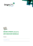
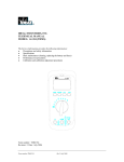
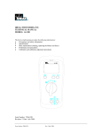
1
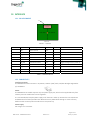
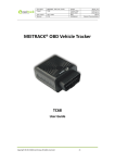
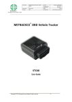
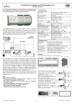
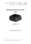
 SISO Hornet (ORG4402)
GPS RECEIVER MODULE Datasheet OriginGPS.com
SISO Hornet ‐ ORG4402 Datasheet
Revision 2.0
Page 1 of 14
January 14, 2015
INDEX
1. 2. 3. 4. 5. 6. 7. 8. 9. 10. 11. 12. 12.1. 12.2. 13. 13.1. 13.2. 14. 14.1. 14.2. 14.3. 14.4. 14.5. 15. SCOPE ................................................................................................................................................................ 3 DISCLAIMER ...................................................................................................................................................... 3 SAFETY INFORMATION ...................................................................................................................................... 3 ESD SENSITIVITY ................................................................................................................................................ 3 CONTACT INFORMATION .................................................................................................................................. 3 RELATED DOCUMENTATION .............................................................................................................................. 3 REVISION HISTORY ............................................................................................................................................ 3 GLOSSARY ......................................................................................................................................................... 4 ABOUT HORNET FAMILY .................................................................................................................................... 5 ABOUT SISO HORNET MODULE ......................................................................................................................... 5 ABOUT ORIGINGPS ............................................................................................................................................ 5 INTERFACE ........................................................................................................................................................ 6 PIN ASSIGNMENT .............................................................................................................................................. 6 CONNECTIVITY .................................................................................................................................................. 6 SOFTWARE FUNCTIONS ..................................................................................................................................... 8 NMEA ................................................................................................................................................................ 8 OSP (SiRF) BINARY ............................................................................................................................................. 9 HANDLING INFORMATION .............................................................................................................................. 13 PRODUCT PACKAGING AND DELIVERY ............................................................................................................. 13 ESD SENSITIVITY .............................................................................................................................................. 13 COMPLIANCES ................................................................................................................................................. 13 SAFETY INFORMATION .................................................................................................................................... 13 DISPOSAL INFORMATION ................................................................................................................................ 13 MECHANICAL SPECIFICATIONS ........................................................................................................................ 14 TABLE INDEX TABLE 1 – RELATED DOCUMENTATION ............................................................................................................................. 3 TABLE 2 – REVISION HISTORY ............................................................................................................................................ 3 TABLE 3 – ORG4402 PIN‐OUT ............................................................................................................................................ 6 TABLE 4 – NMEA PROTOCOL OUTPUT MESSAGES ............................................................................................................. 9 TABLE 5 – NMEA PROTOCOL INPUT MESSAGES ................................................................................................................ 9 TABLE 6 – OSP BINARY OUTPUT MESSAGES .................................................................................................................... 10 TABLE 7 – OSP BINARY INPUT MESSAGES ....................................................................................................................... 11 TABLE 2 – OSP BINARY INPUT MESSAGES ....................................................................................................................... 13 TABLE 2 – ORG4402 MECHANICAL INFORMATION .......................................................................................................... 14 FIGURE INDEX FIGURE 1 – ORG4402 ........................................................................................................................................................ 6 FIGURE 2 – ON_OFF TIMING ............................................................................................................................................. 7 FIGURE 3 – ORG4402 MECHANICAL DRAWING ............................................................................................................... 14 SISO Hornet ‐ ORG4402 Datasheet
Revision 2.0
Page 2 of 14
January 14, 2015
1. SCOPE This document describes the features and specifications of SISO Hornet ORG4402 GPS receiver module. 2. DISCLAIMER All trademarks are properties of their respective owners. Performance characteristics listed in this document do not constitute a warranty or guarantee of product performance. OriginGPS assumes no liability or responsibility for any claims or damages arising out of the use of this document, or from the use of integrated circuits based on this document. OriginGPS assumes no liability or responsibility for unintentional inaccuracies or omissions in this document. OriginGPS reserves the right to make changes in its products, specifications and other information at any time without notice. OriginGPS reserves the right to conduct, from time to time, and at its sole discretion, firmware upgrades. As long as those FW improvements have no material change on end customers, PCN may not be issued. OriginGPS navigation products are not recommended to use in life saving or life sustaining applications. 3. SAFETY INFORMATION Improper handling and use can cause permanent damage to the product. 4. ESD SENSITIVITY This product is ESD sensitive device and must be handled with care. 5. CONTACT INFORMATION Support ‐ [email protected] or Online Form Marketing and sales ‐ [email protected] Web – www.origingps.com 6. RELATED DOCUMENTATION № DOCUMENT NAME 1 Micro Spider – ORG4475 Evaluation Kit Datasheet 2 Micro Spider – ORG4475 Product Change Notification 3 Spider and Hornet ‐ Software User Manual for CSR® based receivers 4 Spider and Hornet ‐ NMEA Protocol Reference Manual for CSR® based receivers 5 Spider and Hornet ‐ One Socket Protocol Reference Manual for CSR® based receivers 6 Spider and Hornet ‐ Host Interface Application Note 7 Spider and Hornet ‐ Low Power Modes Application Note 8 Spider and Hornet ‐ Jammer Detector and Remover Application Note 9 Spider and Hornet ‐ Client Generated Extended Ephemeris Application Note 10 Spider and Hornet ‐ Server Generated Extended Ephemeris Application Note 11 Spider and Hornet ‐ Ephemeris Push Application Note TABLE 1 – RELATED DOCUMENTATION 7. REVISION HISTORY REVISION DATE CHANGE DESCRIPTION B00 February 2, 2011 First release 2.0 January 14, 2015 Format update TABLE 2 – REVISION HISTORY SISO Hornet ‐ ORG4402 Datasheet
Revision 2.0
Page 3 of 14
January 14, 2015
8. GLOSSARY A‐GNSS Assisted GNSS BPF Band Pass Filter CE European Community conformity mark CGEE™ Client Generated Extended Ephemeris CMOS Complementary Metal‐Oxide Semiconductor COMPASS PRC GNSS (same as BDS BeiDou‐2 Navigation Satellite System) EGNOS European Geostationary Navigation Overlay Service EMC Electro‐Magnetic Compatibility ESD Electro‐Static Discharge EVB Evaluation Board EVK Evaluation Kit FCC Federal Communications Commission GALILEO EU GNSS GLONASS Global Navigation Satellite System GNSS Global Navigation Satellite System GPS Global Positioning System I²C Inter‐Integrated Circuit IC Integrated Circuit ISO International Organization for Standardization LDO Low Dropout regulator LGA Land Grid Array LNA Low Noise Amplifier MSAS Multi‐functional Satellite Augmentation System MSL Moisture Sensitivity Level NFZ™ Noise‐Free Zones System NMEA National Marine Electronics Association MEMS MicroElectroMechanical Systems PCB Printed Circuit Board PPS Pulse Per Second QZSS Quasi‐Zenith Satellite System REACH Registration, Evaluation, Authorisation and Restriction of Chemical substances RF Radio Frequiency RHCP Right‐Hand Circular Polarized RoHS Restriction of Hazardous Substances directive ROM Read‐Only Memory RTC Real‐Time Clock SAW Surface Acoustic Wave SBAS Satellite‐Based Augmentation Systems SGEE™ Server Generated Extended Ephemeris SIP System In Package SMD Surface Mounted Device SMT Surface‐Mount Technology SOC System On Chip SPI Serial Peripheral Interface TCXO Temperature‐Compensated Crystal Oscillator TTFF Time To First Fix TTL Transistor‐Transistor Logic UART Universal Asynchronous Receiver/Transmitter WAAS Wide Area Augmentation System SISO Hornet ‐ ORG4402 Datasheet
Revision 2.0
Page 4 of 14
January 14, 2015
9. ABOUT HORNET FAMILY OriginGPS’ Hornet family is offering the industry’s smallest fully‐integrated, highly‐sensitive GPS and GNSS modules with integrated antennas or on‐board RF connectors. Hornet family features OriginGPS' proprietary NFZ™ technology for high sensitivity and noise immunity even under marginal signal condition, commonly found in urban canyons, under dense foliage or when the receiver’s position in space rapidly changes. Hornet family enables the shortest TTM (Time‐To‐Market) with minimal design risks. Just connect power supply on a single layer PCB. 10. ABOUT SISO HORNET MODULE SISO Hornet offers an optimized receiver and antenna combination with unconditional frequency stability, improved noise immunity, higher sensitivity, and enhanced SNR (Signal to Noise) levels. The optimized combination not only decreases the footprint, but also minimizes design risks and reduces time to market. Measuring only 17x17x4.8mm and weighing 11 gr., SISO Hornet is a small fully integrated GPS antenna module. Despite its small size and weight, the Hornet family integrates a patch antenna element, LNA, SAW filter, TCXO, RTC crystal, RF shield and Power Management Unit with SiRFStarIV™ GPS processor. The SISO Hornet module offers superior sensitivity and outstanding performance, achieving rapid time to first fix (TTFF) in less than 1sec., accuracy of approximately 1m, and tracking sensitivity down to ‐163dB 11. ABOUT ORIGINGPS OriginGPS is a world leading designer, manufacturer and supplier of miniature positioning modules, antenna modules and antenna solutions. OriginGPS modules introduce unparalleled sensitivity and noise immunity by incorporating Noise Free Zone system (NFZ™) proprietary technology for faster position fix and navigation stability even under challenging satellite signal conditions. Founded in 2006, OriginGPS is specializing in development of unique technologies that miniaturize RF modules, thereby addressing the market need for smaller wireless solutions. SISO Hornet ‐ ORG4402 Datasheet
Revision 2.0
Page 5 of 14
January 14, 2015
12. INTERFACE 12.1. PIN ASSIGNMENT Pin 1
ZIF Connector
Bottom View
FIGURE 1 – ORG4402 Pad Number Pad Name Pad Description Direction Default Notes 1 GND System Ground Power 2 1PPS UTC Time Mark Output Low 1.8V compatible 3 GPS_nRESET Asynchronous Reset Input High 4 GPS_RX UART Receive
Input High VIH(max) = 3.6V 5 WAKEUP Power State Indicator Output High for Full Power, Low for Hibernate
6 GPS_ON Power State Control
Input Low Toggle Low‐High‐Low for power up 7 GPS_EN Module Enable Input
High Drive low to inhibit the module 8 GPS_TX UART Transmit
Output Low VOH = VCC – 0.1V 9 VCC System Power Power 2.1‐ 5.5V 10 NC Not Connected
TABLE 3 – ORG4402 PIN‐OUT 12.2. CONNECTIVITY Interface connector The ORG4402 interface connector is 10 position, 0.50mm (.020") Pitch, FFC/FPC ZIF Right Angle Molex p/n 527461071 Power The ORG4402 series module requires only one power supply VCC, which can be supplied directly from a battery since the module has internal regulators. It is recommended to keep the power supply on all the time in order to maintain the non‐volatile RTC and RAM active for fastest possible TTFF. When the VCC is powered off settings are reset to factory default and the receiver performs Cold Start on next power up. Power supply VCC range is 2.1 to 5.5V DC. SISO Hornet ‐ ORG4402 Datasheet
Revision 2.0
Page 6 of 14
January 14, 2015
Typical ICC current is [email protected] during acquisition. Peak ICC current is 50 mA. Power supply current consumption varies according to the processor load and satellite acquisition. Typical ICC current in Hibernate state is 50µA. Voltage ripple below 50mVPP allowed for frequency between 100KHz and 3MHz. Voltage ripple below 15mVPP allowed for frequency above 3MHz. Higher voltage ripple may compromise the ORG4402 module performance. The under voltage lockout (UVLO) circuit prevents the device from misoperation at low input voltages. The UVLO circuit prevents the integrated DC‐DC switch‐mode regulator from turning on the switch or rectifier MOSFET under undefined conditions. It has a UVLO threshold set to 1.8V. Fully functional operation is permitted for input voltage down to the falling UVLO threshold level. The converter starts operation again once the input voltage trips the rising UVLO threshold level. Ground Single Ground pad should be connected to the main Ground with shortest possible trace or via. Enable input The Enable control input can be used to fully inhibit the ORG4402 module. Enable signal is active low and has internal 81kΩ pull‐up resistor. Do not connect to this input if the feature is not in use. Host Control Interface ON OFF input The ON_OFF control input can be used to switch the receiver between Hibernate or Full Power states and also to generate interrupt in Push‐to‐Fix operation. The ON_OFF interrupt is generated by a low‐high‐low toggle, which should be longer than 62µs and less than 1s (100ms pulse length recommended). ON_OFF interrupts with less than 1 sec intervals are not recommended. Multiple switch bounce pulses are recommended to be filtered out. Input levels are 1.8 to 3.6V. ON_OFF input is rising edge triggered. Do not drive high permanently or pull‐up this input. FIGURE 2 – ON_OFF TIMING WAKEUP output The WAKEUP pad is an output from the ORG4402 used to flag for power state. A low on this output indicates that the module is in one of its low‐power states: Hibernate or Standby. A high on this output indicates that the module is in Full Power state. Wakeup output is LVCMOS 1.8V compatible. Do not load this output if the feature is not in use. nRESET input SISO Hornet ‐ ORG4402 Datasheet
Revision 2.0
Page 7 of 14
January 14, 2015
The Power‐on‐Reset (POR) is generated internally in the ORG4402 module. Additionally, manual reset option is available through nRESET pad. Resetting the module clears the RTC block and configuration settings become default. nRESET pad is active low and has internal pull‐up resistor. nRESET signal should be applied for at least 1µs. nRESET input has internal pull‐up of 86KΩ. Do not drive this input high. Do not connect to this input if the feature is not in use. 1PPS output The pulse‐per‐second (PPS) output provides a pulse signal for timing purposes. Pulse length (high state) is 200ms about 1µs synchronized to full UTC second. The UTC time message is generated and put into output FIFO 300ms after PPS. The exact time between the PPS and UTC time message delivery depends on message rate, message queue and communication baud rate. 1PPS output is LVCMOS 1.8V compatible. Do not connect to this output if the feature is not in use Host Data Interface UART TX used for GPS data reports. RX used for receiver control. The default protocol is NMEA@4,800bps 8‐N‐1. Baud rates are selectable from 1200bps to 1.25Mbps. The configuration for baud rates and respective protocols can be changed by commands via NMEA or OSP (SiRF Binary) protocols. Input levels are 1.8 to 3.6V. Output level of the UART TX is VCC – 0.1V 13. SOFTWARE FUNCTIONS The ORG4402 series module supports NMEA‐0183 ASCII protocol and One Socket Protocol (SiRF Binary). 13.1. NMEA NMEA Output Messages Message Description
GGA Time, position and fix type data GLL1 Latitude, longitude, UTC time of position fix and status GSA GPS receiver operating mode, satellites used in the position solution and DOP values GSV The number of GPS satellites in view, satellite ID, elevation, azimuth and SNR values RMC Time, date, position, course and speed data VTG1 Course and speed information relative to the ground ZDA2 PPS timing message (synchronized to PPS) 155 Extended Ephemeris Proprietary Message 156,0x20 ECLM ACK/NACK 156,0x21 ECLM EE Get Age response 156,0x22 ECLM Get SGEE Age response 156,0x23 ECLM Download Initiate Request SISO Hornet ‐ ORG4402 Datasheet
Revision 2.0
Page 8 of 14
January 14, 2015
156,0x24 ECLM Erase Storage File 156,0x25 ECLM Update File Content 156,0x26 ECLM Request File Content 1602 Watchdog Timeout and Exception Condition TABLE 4 – NMEA PROTOCOL OUTPUT MESSAGES NMEA Input Messages Message ID Message Description
100 Set Serial Port Set UART parameters and protocol 101 Navigation Initialization Parameters required for start using X/Y/Z 103 Query/Rate Control Query standard NMEA message and/or set output rate 104 LLA Navigation Initialization Parameters required for start using Lat/Lon/Alt 105 Development Data On/Off Development Data messages On/Off 106 Select Datum Selection of an alternative map datum 107 Extended ephemeris proprietary message 108 Extended ephemeris proprietary message 110 Extended ephemeris debug 114,0x16 ECLM start download 114,0x17 ECLM file size 114,0x18 ECLM packet data 114,0x19 ECLM Get EE Age 114,0x1A ECLM Get SGEE Age 114,0x1B ECLM Host File Content 114,0x1C ECLM Host ACK/NACK 1172 System Turn Off 120 Storage Configuration Setting TABLE 5 – NMEA PROTOCOL INPUT MESSAGES Note: 1. Not transmitted by default, can be enabled by $PSRF103 command 2. Not implemented in current firmware 13.2. OSP (SiRF) BINARY OSP Binary Output Messages MID MID (dec) Definition (hex) Sub ID (hex)
Sub ID (dec) Definition 0 x 02 2 Measured Navigation Data 0 x 03 3 True Tracker Data 0 x 04 4 Measured Tracking Data 0 x 06 6 SW Version 0 x 07 7 Clock Status 0 x 08 8 50 BPS Subframe Data 0 x 09 9 Throughput 0 x 0A 10 Error ID 0 x 0B 11 Command Acknowledgement SISO Hornet ‐ ORG4402 Datasheet
Revision 2.0
Page 9 of 14
January 14, 2015
0 x °C 12 Command No Acknowledgement 0 x 0D 13 Visible List 0 x 0E 14 Almanac Data 0 x 0F 15 Ephemeris Data 0 x 10 16 Test Mode 1 0 x 12 18 Ok To Send 0 x 13 19 Navigation Parameters 0 x 14 20 Test Mode 2 0 x 1B 27 DGPS Status 0 x 1C 28 Nav. Lib. Measurement Data 0 x 1E 30 Nav. Lib. SV State Data 0 x 1F 31 Nav. Lib. Initialization Data 0 x FF 255 Development Data TABLE 6 – OSP BINARY OUTPUT MESSAGES MID (hex) OSP Binary Input Messages MID Definition (dec) Sub ID (hex) Sub ID (dec) Definition 0 x 35 53 Advanced Power Management 0 x 80 128 Initialize Data Source 0 x 81 129 Switch to NMEA Protocol 0 x 82 130 Set Almanac (upload) 0 x 84 132 Software Version (Poll) 0 x 86 134 Set Main Serial Port 0 x 87 135 Switch Protocol 0 x 88 136 Mode Control 0 x 89 137 DOP Mask 0 x 8A 138 MID_SET_DGPS_MODE 0 x 8B 139 Elevation Mask 0 x 8C 140 Power Mask 0 x 8D 141 Editing Residual 0 x 8E 142 Steady‐State Detection 0 x 8F 143 Static Navigation 0 x 90 144 Poll Clock Status 0 x 92 146 Poll Almanac 0 x 93 147 Poll Ephemeris 0 x 95 149 Set Ephemeris (upload) 0 x 96 150 Switch Operating Mode 0 x 97 151 Set Trickle Power Parameters 0 x 98 152 Poll Navigation Parameters 0 x A5 165 Set UART Configuration 0 x A6 166 Set Message Rate SISO Hornet ‐ ORG4402 Datasheet
Revision 2.0
Page 10 of 14
January 14, 2015
0 x A7 167 Low Power Acquisition Parameters 0 x A8 168 MID_POLL_CMD_PARAM 0 x A9 169 Set Datum 0 x AA 170 Set SBAS Parameters 0 x 01 1 Set DrNavInit 0 x 02 2 Set DrNavMode 0 x 03 3 Set GyrFactCal 0 x 04 4 Set DrSensParam 0 x 05 5 Poll DrValid 0 x 06 6 Poll GyrFactCal 0 x 07 7 Poll DrSensParam 0 x 13 19 DR Debug Information 0 x 14 20 Patch Storage Control 0 x 22 34 Patch Memory Load Request 0 x 26 38 Patch Memory Exit Request 0 x 28 40 Patch Memory Start Request 0 x 90 144 Patch Manager Prompt 0 x 91 145 Patch Manager Ack. 0 x AC 0 x AF 0 x B2 172 175 178 MID_DrIn Send Command String SIRF_MSG_SSB_TRACKER_IC 0 x CD 205 Set Generic Software Control 0 x 10 16 Software Commanded OFF 0 x D1 209 MID_QUERY_REQ 0 x D2 210 MID_POS_REQ TABLE 7 – OSP BINARY INPUT MESSAGES MID (hex) 0 x D3 0 x D4 MID (dec) 211 212 Definition MID_SET_AIDING MID_STATUS_REQ SISO Hornet ‐ ORG4402 Datasheet
Sub ID (hex) Sub ID (dec) Definition 0 x 01 1 SET_IONO 0 x 02 2 SET_EPH_CLOCK 0 x 03 3 SET_ALM 0 x 04 4 SET_ACQ_ASSIST 0 x 05 5 SET_RT_INTEG 0 x 06 6 SET_UTC_MODEL 0 x 07 7 SET_GPS_TOW_ASSIST 0 x 08 8 SET_AUX_NAV 0 x 09 9 SET_AIDING_AVAIL 0 x 01 1 EPH_REQ 0 x 02 2 ALM_REQ 0 x 03 3 B_EPH_REQ 0 x 04 4 TIME_FREQ_APPROX_POS_REQ 0 x 05 5 CH_LOAD_REQ 0 x 06 6 CLIENT_STATUS_REQ 0 x 07 7 OSP_REV_REQ Revision 2.0
Page 11 of 14
January 14, 2015
0 x D5 213 MID_SESSION_CONTROL_REQ 0 x D6 214 MID_HW_CONFIG_RESP 0xD7 215 MID_AIDING_RESP 0 x 08 8 SERIAL_SETTINGS_REQ 0 x 01 1 SESSION_OPEN_REQ 0 x 02 2 SESSION_CLOSE_REQ 0 x 01 1 APPROX_MS_POS_RESP 0 x 02 2 TIME_TX_RESP 0 x 03 3 FREQ_TX_RESP 0 x 04 4 SET_NBA_SF1_2_3 0 x 05 5 SET_NBA_SF4_5 0xD8 216 MID_MSG_ACK_IN 0 x 01 1 ACK_NACK_ERROR 0 x 02 2 REJECT 0xD9 217 0 x 01 1 SENSOR_ON_OFF 0 x 00 0 FP_MODE_REQ 0 x 01 1 APM_REQ 0 x 02 2 MPM_REQ 0 x 03 3 TP_REQ 0 x 04 4 PTF_REQ 0 x 01 1 VCTCXO 0 x 02 2 ON_OFF_SIG_CONFIG 0 x 01 1 CONFIG 0 x 02 2 EVENT_REG 0 x 03 3 COMMAND_SCAN 0 x 04 4 CUSTOM_MON_CONFIG 0 x 05 5 FFT_NOTCH_SETUP 0 x 06 6 STATISTICS 0 x 07 7 Statistics with Aiding 0xDA 0xDB 0xDC 0xE1 218 219 220 225 MID_PWR_MODE_REQ MID_HW_CTRL_IN MID_CW_CONTROLLER_REQ MID_SiRFOutput Table 2-4: OSP BINARY INPUT MESSAGES
MID (hex) 0xE8 MID (dec) 232 Definition MID_EE_INPUT SISO Hornet ‐ ORG4402 Datasheet
Sub ID (hex) Sub ID (dec) Definition 0 x 01 1 SSB_EE_SEA_PROVIDE_EPH 0 x 02 2 SSB_EE_POLL_STATE 0 x 10 16 SSB_EE_FILE_DOWNLOAD 0 x 11 17 SSB_EE_QUERY_AGE 0 x 12 18 SSB_EE_FILE_PART 0 x 13 19 SSB_EE_DOWNLOAD_TCP 0 x 14 20 SSB_EE_SET_EPHEMERIS 0 x 15 21 SSB_EE_FILE_STATUS 0 x 16 22 ECLM Start Download 0 x 17 23 ECLM File Size 0 x 18 24 ECLM Packet Data Revision 2.0
Page 12 of 14
January 14, 2015
0 x 19 25 Get EE Age 0 x 1A 26 Get SGEE Age 0 x 1B 27 ECLM Host File Content 0 x 1C 28 ECLM Host ACK/NACK 0 x 1D 29 ECLM Get NVM Header 0 x FD 253 EE_STORAGE_CONTROL 0 x FE 254 SSB_EE_DISABLE_EE_SECS TABLE 8 – OSP BINARY INPUT MESSAGES 14. HANDLING INFORMATION 14.1. PRODUCT PACKAGING AND DELIVERY -TBA14.2. ESD SENSITIVITY The ORG4402 modules are ESD sensitive devices and should be handled with care. 14.3. COMPLIANCES The ORG4402 modules comply with the following standards: Pb‐Free/RoHS (Directive 2002/95/EC on the restriction of the use of certain hazardous substances in electrical and electronic equipment) ISO 9001:2000 accredited manufacturing facility 14.4. SAFETY INFORMATION Improper handling and use can cause permanent damage to the device. There is also the possible risk of personal injury from mechanical trauma or shocking hazard. 14.5. DISPOSAL INFORMATION The product should not be treated as household waste. For more detailed information about recycling electronic components, please contact your local waste management authority. SISO Hornet ‐ ORG4402 Datasheet
Revision 2.0
Page 13 of 14
January 14, 2015
15. MECHANICAL SPECIFICATIONS TOP VIEW
SIDE VIEW
BOTTOM VIEW
28.0 ± 0.2
28.0 ± 0.2
ZIF Connector
1.1± 0.1
1.1± 0.1
~7.0 ± 0.2
18.5 ± 0.2
18.5 ± 0.2
0.5 max.
28.0 ± 0.2
FIGURE 3 – ORG4402 MECHANICAL DRAWING Dimensions Length Width Height Weight mm 28.0 ± 0.2 18.5 ± 0.2 7.0 ± 0.2 gr
8 inch 1.102 ± 0.008 0.728 ± 0.008 0.276 ± 0.008 oz 0.28 TABLE 9 – ORG4402 MECHANICAL INFORMATION SISO Hornet ‐ ORG4402 Datasheet
Revision 2.0
Page 14 of 14
January 14, 2015