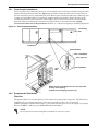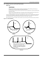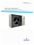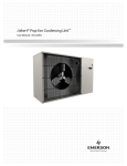
1
Precision Cooling
For Business-Critical Continuity™
Liebert® Mini-Mate2™
User Manual - 8 Tons, 50 & 60Hz
TABLE OF CONTENTS
IMPORTANT SAFETY INSTRUCTIONS . . . . . . . . . . . . . . . . . . . . . . . . . . . . . . . . . . . . . . . . . . . . . . . .1
MODEL NUMBER NOMENCLATURE . . . . . . . . . . . . . . . . . . . . . . . . . . . . . . . . . . . . . . . . . . . . . . . . .3
1.0
INTRODUCTION . . . . . . . . . . . . . . . . . . . . . . . . . . . . . . . . . . . . . . . . . . . . . . . . . . . . . . . . . .7
1.1
Designed to Match Computer and Electronic Equipment Needs—From Installation
to Operation . . . . . . . . . . . . . . . . . . . . . . . . . . . . . . . . . . . . . . . . . . . . . . . . . . . . . . . . . . . . . . . . 7
2.0
STANDARD FEATURES—8 TON SYSTEMS . . . . . . . . . . . . . . . . . . . . . . . . . . . . . . . . . . . . . .8
2.1
Evaporator Section—Split System . . . . . . . . . . . . . . . . . . . . . . . . . . . . . . . . . . . . . . . . . . . . . . 8
2.2
Condensing Unit Section—Split System. . . . . . . . . . . . . . . . . . . . . . . . . . . . . . . . . . . . . . . . . . 8
2.2.1
2.2.2
2.2.3
Indoor Centrifugal Fan Condensing Units . . . . . . . . . . . . . . . . . . . . . . . . . . . . . . . . . . . . . . . . . 8
Outdoor Prop-Fan Condensing Units . . . . . . . . . . . . . . . . . . . . . . . . . . . . . . . . . . . . . . . . . . . . . 8
Indoor Water/Glycol Condensing Units. . . . . . . . . . . . . . . . . . . . . . . . . . . . . . . . . . . . . . . . . . . . 8
2.3
Chilled Water Units . . . . . . . . . . . . . . . . . . . . . . . . . . . . . . . . . . . . . . . . . . . . . . . . . . . . . . . . . . 8
2.4
System Controls . . . . . . . . . . . . . . . . . . . . . . . . . . . . . . . . . . . . . . . . . . . . . . . . . . . . . . . . . . . . . 8
2.4.1
2.4.2
Three-Stage Cooling . . . . . . . . . . . . . . . . . . . . . . . . . . . . . . . . . . . . . . . . . . . . . . . . . . . . . . . . . . . 9
Other Standard Control Features . . . . . . . . . . . . . . . . . . . . . . . . . . . . . . . . . . . . . . . . . . . . . . . . 9
3.0
OPTIONAL FACTORY-INSTALLED FEATURES - EVAPORATOR/CHILLED WATER UNITS . . . . . 10
3.1
Reheat . . . . . . . . . . . . . . . . . . . . . . . . . . . . . . . . . . . . . . . . . . . . . . . . . . . . . . . . . . . . . . . . . . . . 10
3.2
Humidifier. . . . . . . . . . . . . . . . . . . . . . . . . . . . . . . . . . . . . . . . . . . . . . . . . . . . . . . . . . . . . . . . . 10
3.3
Sensors . . . . . . . . . . . . . . . . . . . . . . . . . . . . . . . . . . . . . . . . . . . . . . . . . . . . . . . . . . . . . . . . . . . 10
3.4
Switches and Motors . . . . . . . . . . . . . . . . . . . . . . . . . . . . . . . . . . . . . . . . . . . . . . . . . . . . . . . . 10
3.5
Free-Cooling . . . . . . . . . . . . . . . . . . . . . . . . . . . . . . . . . . . . . . . . . . . . . . . . . . . . . . . . . . . . . . . 10
3.6
Optional Configuration—Prop Fan Condensing Units . . . . . . . . . . . . . . . . . . . . . . . . . . . . . 11
3.7
Optional Configurations—Water/Glycol Condensing Units . . . . . . . . . . . . . . . . . . . . . . . . . 11
3.8
Optional Configuration—Chilled Water Units . . . . . . . . . . . . . . . . . . . . . . . . . . . . . . . . . . . . 11
4.0
SHIP-LOOSE ACCESSORIES—FIELD-INSTALLED . . . . . . . . . . . . . . . . . . . . . . . . . . . . . . . . 12
4.1
Remote Monitoring, Autochangeover and Leak Detection Equipment . . . . . . . . . . . . . . . . . 12
5.0
SITE PREPARATION AND INSTALLATION . . . . . . . . . . . . . . . . . . . . . . . . . . . . . . . . . . . . . . . 14
5.1
Installation Considerations . . . . . . . . . . . . . . . . . . . . . . . . . . . . . . . . . . . . . . . . . . . . . . . . . . . 14
5.1.1
5.1.2
Room Preparation. . . . . . . . . . . . . . . . . . . . . . . . . . . . . . . . . . . . . . . . . . . . . . . . . . . . . . . . . . . . 14
Location Considerations. . . . . . . . . . . . . . . . . . . . . . . . . . . . . . . . . . . . . . . . . . . . . . . . . . . . . . . 15
5.2
Ceiling Unit Weights . . . . . . . . . . . . . . . . . . . . . . . . . . . . . . . . . . . . . . . . . . . . . . . . . . . . . . . . 17
5.3
Equipment Inspection Upon Receipt. . . . . . . . . . . . . . . . . . . . . . . . . . . . . . . . . . . . . . . . . . . . 17
5.4
Installing the Ceiling Units . . . . . . . . . . . . . . . . . . . . . . . . . . . . . . . . . . . . . . . . . . . . . . . . . . . 18
5.4.1
5.4.2
5.4.3
5.4.4
5.5
Close-Coupled Installations . . . . . . . . . . . . . . . . . . . . . . . . . . . . . . . . . . . . . . . . . . . . . . . . . . . .
Evaporator Air Distribution. . . . . . . . . . . . . . . . . . . . . . . . . . . . . . . . . . . . . . . . . . . . . . . . . . . .
Electrical Connections, Evaporator or Chilled-Water Unit . . . . . . . . . . . . . . . . . . . . . . . . . . .
Piping Connections and Coolant Requirements . . . . . . . . . . . . . . . . . . . . . . . . . . . . . . . . . . . .
19
19
20
23
Indoor Air-Cooled Centrifugal Fan Condensing Unit Installation . . . . . . . . . . . . . . . . . . . . 30
i
5.5.1
5.5.2
5.5.3
5.5.4
5.6
Location Considerations. . . . . . . . . . . . . . . . . . . . . . . . . . . . . . . . . . . . . . . . . . . . . . . . . . . . . . . 34
Electrical Connections . . . . . . . . . . . . . . . . . . . . . . . . . . . . . . . . . . . . . . . . . . . . . . . . . . . . . . . . 34
Piping Connections . . . . . . . . . . . . . . . . . . . . . . . . . . . . . . . . . . . . . . . . . . . . . . . . . . . . . . . . . . . 34
Indoor Water-Cooled and Glycol-Cooled Condensing Unit Installation . . . . . . . . . . . . . . . . 37
5.7.1
5.7.2
5.7.3
5.8
30
30
31
31
Outdoor Air-Cooled Condensing Unit Installation . . . . . . . . . . . . . . . . . . . . . . . . . . . . . . . . . 34
5.6.1
5.6.2
5.6.3
5.7
Location Considerations. . . . . . . . . . . . . . . . . . . . . . . . . . . . . . . . . . . . . . . . . . . . . . . . . . . . . . .
Electrical Connections - Condensing Unit . . . . . . . . . . . . . . . . . . . . . . . . . . . . . . . . . . . . . . . .
Piping Connections . . . . . . . . . . . . . . . . . . . . . . . . . . . . . . . . . . . . . . . . . . . . . . . . . . . . . . . . . . .
Ducting . . . . . . . . . . . . . . . . . . . . . . . . . . . . . . . . . . . . . . . . . . . . . . . . . . . . . . . . . . . . . . . . . . . .
Location Considerations. . . . . . . . . . . . . . . . . . . . . . . . . . . . . . . . . . . . . . . . . . . . . . . . . . . . . . . 37
Electrical Connections . . . . . . . . . . . . . . . . . . . . . . . . . . . . . . . . . . . . . . . . . . . . . . . . . . . . . . . . 37
Piping Connections . . . . . . . . . . . . . . . . . . . . . . . . . . . . . . . . . . . . . . . . . . . . . . . . . . . . . . . . . . . 38
Optional Equipment Piping . . . . . . . . . . . . . . . . . . . . . . . . . . . . . . . . . . . . . . . . . . . . . . . . . . . 42
5.8.1
Free-Cooling Coil (GLYCOOL) . . . . . . . . . . . . . . . . . . . . . . . . . . . . . . . . . . . . . . . . . . . . . . . . . 42
5.9
Checklist for Completed Installation . . . . . . . . . . . . . . . . . . . . . . . . . . . . . . . . . . . . . . . . . . . 43
6.0
MICROPROCESSOR CONTROL . . . . . . . . . . . . . . . . . . . . . . . . . . . . . . . . . . . . . . . . . . . . . . 44
6.1
Feature Overview . . . . . . . . . . . . . . . . . . . . . . . . . . . . . . . . . . . . . . . . . . . . . . . . . . . . . . . . . . . 44
6.2
Main Menu <Menu>. . . . . . . . . . . . . . . . . . . . . . . . . . . . . . . . . . . . . . . . . . . . . . . . . . . . . . . . . 45
6.3
Setpoints . . . . . . . . . . . . . . . . . . . . . . . . . . . . . . . . . . . . . . . . . . . . . . . . . . . . . . . . . . . . . . . . . . 45
6.4
Status . . . . . . . . . . . . . . . . . . . . . . . . . . . . . . . . . . . . . . . . . . . . . . . . . . . . . . . . . . . . . . . . . . . . 46
6.5
Active Alarms . . . . . . . . . . . . . . . . . . . . . . . . . . . . . . . . . . . . . . . . . . . . . . . . . . . . . . . . . . . . . . 46
6.6
Alarm History . . . . . . . . . . . . . . . . . . . . . . . . . . . . . . . . . . . . . . . . . . . . . . . . . . . . . . . . . . . . . . 46
6.7
Time. . . . . . . . . . . . . . . . . . . . . . . . . . . . . . . . . . . . . . . . . . . . . . . . . . . . . . . . . . . . . . . . . . . . . . 46
6.8
Date . . . . . . . . . . . . . . . . . . . . . . . . . . . . . . . . . . . . . . . . . . . . . . . . . . . . . . . . . . . . . . . . . . . . . . 46
6.9
Setback . . . . . . . . . . . . . . . . . . . . . . . . . . . . . . . . . . . . . . . . . . . . . . . . . . . . . . . . . . . . . . . . . . . 47
6.10
Setup Operation . . . . . . . . . . . . . . . . . . . . . . . . . . . . . . . . . . . . . . . . . . . . . . . . . . . . . . . . . . . . 47
6.10.1
6.10.2
6.10.3
6.10.4
6.10.5
6.10.6
6.10.7
Restart Time Delay. . . . . . . . . . . . . . . . . . . . . . . . . . . . . . . . . . . . . . . . . . . . . . . . . . . . . . . . . . .
C/F Degrees. . . . . . . . . . . . . . . . . . . . . . . . . . . . . . . . . . . . . . . . . . . . . . . . . . . . . . . . . . . . . . . . .
Humidity Control Method . . . . . . . . . . . . . . . . . . . . . . . . . . . . . . . . . . . . . . . . . . . . . . . . . . . . .
Lead Compressor . . . . . . . . . . . . . . . . . . . . . . . . . . . . . . . . . . . . . . . . . . . . . . . . . . . . . . . . . . . .
Show DIP Switch . . . . . . . . . . . . . . . . . . . . . . . . . . . . . . . . . . . . . . . . . . . . . . . . . . . . . . . . . . . .
Valve Time . . . . . . . . . . . . . . . . . . . . . . . . . . . . . . . . . . . . . . . . . . . . . . . . . . . . . . . . . . . . . . . . .
CW Flush . . . . . . . . . . . . . . . . . . . . . . . . . . . . . . . . . . . . . . . . . . . . . . . . . . . . . . . . . . . . . . . . . .
47
47
48
48
48
48
48
6.11
Change Passwords . . . . . . . . . . . . . . . . . . . . . . . . . . . . . . . . . . . . . . . . . . . . . . . . . . . . . . . . . . 49
6.12
Calibrate Sensors . . . . . . . . . . . . . . . . . . . . . . . . . . . . . . . . . . . . . . . . . . . . . . . . . . . . . . . . . . . 49
6.13
Alarm Enable . . . . . . . . . . . . . . . . . . . . . . . . . . . . . . . . . . . . . . . . . . . . . . . . . . . . . . . . . . . . . . 49
6.14
Alarm Time Delay . . . . . . . . . . . . . . . . . . . . . . . . . . . . . . . . . . . . . . . . . . . . . . . . . . . . . . . . . . 50
6.15
Common Alarm Enable . . . . . . . . . . . . . . . . . . . . . . . . . . . . . . . . . . . . . . . . . . . . . . . . . . . . . . 50
6.16
Custom Alarms . . . . . . . . . . . . . . . . . . . . . . . . . . . . . . . . . . . . . . . . . . . . . . . . . . . . . . . . . . . . . 50
6.17
Custom Text . . . . . . . . . . . . . . . . . . . . . . . . . . . . . . . . . . . . . . . . . . . . . . . . . . . . . . . . . . . . . . . 51
6.18
Run Diagnostics . . . . . . . . . . . . . . . . . . . . . . . . . . . . . . . . . . . . . . . . . . . . . . . . . . . . . . . . . . . . 52
ii
7.0
SYSTEM PERFORMANCE MICROPROCESSOR CONTROLS . . . . . . . . . . . . . . . . . . . . . . . . . . 56
7.1
Control Type Response Proportional Control . . . . . . . . . . . . . . . . . . . . . . . . . . . . . . . . . . . . . 56
7.2
Cooling . . . . . . . . . . . . . . . . . . . . . . . . . . . . . . . . . . . . . . . . . . . . . . . . . . . . . . . . . . . . . . . . . . . 56
7.2.1
7.2.2
7.2.3
7.3
Reheat . . . . . . . . . . . . . . . . . . . . . . . . . . . . . . . . . . . . . . . . . . . . . . . . . . . . . . . . . . . . . . . . . . . . 57
7.3.1
7.3.2
7.4
Multi-Step Cooling, Compressorized Direct Expansion (DX) Systems . . . . . . . . . . . . . . . . . . 56
Chilled-Water Cooling (8 Ton) . . . . . . . . . . . . . . . . . . . . . . . . . . . . . . . . . . . . . . . . . . . . . . . . . . 56
GLYCOOL Cooling (8 Ton) . . . . . . . . . . . . . . . . . . . . . . . . . . . . . . . . . . . . . . . . . . . . . . . . . . . . 56
Electric Reheat - Staged. . . . . . . . . . . . . . . . . . . . . . . . . . . . . . . . . . . . . . . . . . . . . . . . . . . . . . . 57
SCR Electric Reheat . . . . . . . . . . . . . . . . . . . . . . . . . . . . . . . . . . . . . . . . . . . . . . . . . . . . . . . . . . 57
Dehumidification / Humidification Percent Required . . . . . . . . . . . . . . . . . . . . . . . . . . . . . . 57
7.4.1
7.4.2
7.4.3
Staged Dehumidification, Compressorized Direct Expansion (DX) Systems . . . . . . . . . . . . . 57
Humidification Operation . . . . . . . . . . . . . . . . . . . . . . . . . . . . . . . . . . . . . . . . . . . . . . . . . . . . . 57
Dehumidification Lockout . . . . . . . . . . . . . . . . . . . . . . . . . . . . . . . . . . . . . . . . . . . . . . . . . . . . . 57
7.5
Load Control Features . . . . . . . . . . . . . . . . . . . . . . . . . . . . . . . . . . . . . . . . . . . . . . . . . . . . . . . 57
7.6
Communication. . . . . . . . . . . . . . . . . . . . . . . . . . . . . . . . . . . . . . . . . . . . . . . . . . . . . . . . . . . . . 58
8.0
ALARMS . . . . . . . . . . . . . . . . . . . . . . . . . . . . . . . . . . . . . . . . . . . . . . . . . . . . . . . . . . . . . . 59
8.1
Alarms: Definitions and Troubleshooting . . . . . . . . . . . . . . . . . . . . . . . . . . . . . . . . . . . . . . . . 59
8.1.1
8.1.2
8.1.3
8.1.4
8.1.5
8.1.6
8.1.7
8.1.8
8.2
Custom Alarms . . . . . . . . . . . . . . . . . . . . . . . . . . . . . . . . . . . . . . . . . . . . . . . . . . . . . . . . . . . . . .
High Head Pressure . . . . . . . . . . . . . . . . . . . . . . . . . . . . . . . . . . . . . . . . . . . . . . . . . . . . . . . . . .
Humidity . . . . . . . . . . . . . . . . . . . . . . . . . . . . . . . . . . . . . . . . . . . . . . . . . . . . . . . . . . . . . . . . . . .
Temperature . . . . . . . . . . . . . . . . . . . . . . . . . . . . . . . . . . . . . . . . . . . . . . . . . . . . . . . . . . . . . . . .
Humidifier Problem Alarm . . . . . . . . . . . . . . . . . . . . . . . . . . . . . . . . . . . . . . . . . . . . . . . . . . . .
High-Water Alarm . . . . . . . . . . . . . . . . . . . . . . . . . . . . . . . . . . . . . . . . . . . . . . . . . . . . . . . . . . .
Loss of Power . . . . . . . . . . . . . . . . . . . . . . . . . . . . . . . . . . . . . . . . . . . . . . . . . . . . . . . . . . . . . . .
Short Cycle . . . . . . . . . . . . . . . . . . . . . . . . . . . . . . . . . . . . . . . . . . . . . . . . . . . . . . . . . . . . . . . . .
59
59
60
60
60
60
60
60
Optional/Custom Alarms . . . . . . . . . . . . . . . . . . . . . . . . . . . . . . . . . . . . . . . . . . . . . . . . . . . . . 61
8.2.1
8.2.2
8.2.3
Change Filter . . . . . . . . . . . . . . . . . . . . . . . . . . . . . . . . . . . . . . . . . . . . . . . . . . . . . . . . . . . . . . . 61
High Temperature Sensor . . . . . . . . . . . . . . . . . . . . . . . . . . . . . . . . . . . . . . . . . . . . . . . . . . . . . 61
Smoke Sensor . . . . . . . . . . . . . . . . . . . . . . . . . . . . . . . . . . . . . . . . . . . . . . . . . . . . . . . . . . . . . . . 61
9.0
SYSTEM OPERATION, TESTING, AND MAINTENANCE . . . . . . . . . . . . . . . . . . . . . . . . . . . . . . 62
9.1
System Testing . . . . . . . . . . . . . . . . . . . . . . . . . . . . . . . . . . . . . . . . . . . . . . . . . . . . . . . . . . . . . 62
9.1.1
9.1.2
9.1.3
9.1.4
9.1.5
9.1.6
9.2
62
62
62
62
62
62
Maintenance and Component Operation . . . . . . . . . . . . . . . . . . . . . . . . . . . . . . . . . . . . . . . . 63
9.2.1
9.2.2
9.2.3
9.2.4
9.2.5
9.3
Environmental Control Functions . . . . . . . . . . . . . . . . . . . . . . . . . . . . . . . . . . . . . . . . . . . . . . .
Cooling. . . . . . . . . . . . . . . . . . . . . . . . . . . . . . . . . . . . . . . . . . . . . . . . . . . . . . . . . . . . . . . . . . . . .
Heating . . . . . . . . . . . . . . . . . . . . . . . . . . . . . . . . . . . . . . . . . . . . . . . . . . . . . . . . . . . . . . . . . . . .
Humidification . . . . . . . . . . . . . . . . . . . . . . . . . . . . . . . . . . . . . . . . . . . . . . . . . . . . . . . . . . . . . .
Dehumidification . . . . . . . . . . . . . . . . . . . . . . . . . . . . . . . . . . . . . . . . . . . . . . . . . . . . . . . . . . . .
Remote Shutdown. . . . . . . . . . . . . . . . . . . . . . . . . . . . . . . . . . . . . . . . . . . . . . . . . . . . . . . . . . . .
Electric Panel . . . . . . . . . . . . . . . . . . . . . . . . . . . . . . . . . . . . . . . . . . . . . . . . . . . . . . . . . . . . . . .
Filters . . . . . . . . . . . . . . . . . . . . . . . . . . . . . . . . . . . . . . . . . . . . . . . . . . . . . . . . . . . . . . . . . . . . .
Blower System . . . . . . . . . . . . . . . . . . . . . . . . . . . . . . . . . . . . . . . . . . . . . . . . . . . . . . . . . . . . . .
Electric Reheat . . . . . . . . . . . . . . . . . . . . . . . . . . . . . . . . . . . . . . . . . . . . . . . . . . . . . . . . . . . . . .
Refrigeration System . . . . . . . . . . . . . . . . . . . . . . . . . . . . . . . . . . . . . . . . . . . . . . . . . . . . . . . . .
63
63
63
64
64
Replacement Procedures . . . . . . . . . . . . . . . . . . . . . . . . . . . . . . . . . . . . . . . . . . . . . . . . . . . . . 66
iii
9.3.1
9.3.2
9.3.3
Compressor Replacement. . . . . . . . . . . . . . . . . . . . . . . . . . . . . . . . . . . . . . . . . . . . . . . . . . . . . . 66
Steam Generating Humidifier—Operation Procedures . . . . . . . . . . . . . . . . . . . . . . . . . . . . . . 68
Humidifier Circuit Board Adjustments. . . . . . . . . . . . . . . . . . . . . . . . . . . . . . . . . . . . . . . . . . . 69
10.0
MAINTENANCE INSPECTION CHECKLIST . . . . . . . . . . . . . . . . . . . . . . . . . . . . . . . . . . . . . . . 70
11.0
TROUBLESHOOTING . . . . . . . . . . . . . . . . . . . . . . . . . . . . . . . . . . . . . . . . . . . . . . . . . . . . . 71
FIGURES
Figure 1
Figure 2
Figure 3
Figure 4
Figure 5
Figure 6
Figure 7
Figure 8
Figure 9
Figure 10
Figure 11
Figure 12
Figure 13
Figure 14
Figure 15
Figure 16
Figure 17
Figure 18
Figure 19
Figure 20
Figure 21
Figure 22
Figure 23
Figure 24
Figure 25
Figure 26
Figure 27
Figure 28
Figure 29
Figure 30
Figure 31
Figure 32
Figure 33
Figure 34
Figure 35
Model number nomenclature—Evaporator Units. . . . . . . . . . . . . . . . . . . . . . . . . . . . . . . . . . . . . . . 3
Model number nomenclature—Air-cooled indoor condensing units . . . . . . . . . . . . . . . . . . . . . . . . 4
Air-cooled systems—Outdoor prop fan condensing units . . . . . . . . . . . . . . . . . . . . . . . . . . . . . . . . . 4
Water/glycol-cooled systems—Indoor condensing units . . . . . . . . . . . . . . . . . . . . . . . . . . . . . . . . . . 5
Model number nomenclature—Chilled water units . . . . . . . . . . . . . . . . . . . . . . . . . . . . . . . . . . . . . 6
Improved load tracking. . . . . . . . . . . . . . . . . . . . . . . . . . . . . . . . . . . . . . . . . . . . . . . . . . . . . . . . . . . . 9
Wall-box . . . . . . . . . . . . . . . . . . . . . . . . . . . . . . . . . . . . . . . . . . . . . . . . . . . . . . . . . . . . . . . . . . . . . . . . 9
Free-cooling option—example . . . . . . . . . . . . . . . . . . . . . . . . . . . . . . . . . . . . . . . . . . . . . . . . . . . . . 11
System configurations—air cooled systems. . . . . . . . . . . . . . . . . . . . . . . . . . . . . . . . . . . . . . . . . . . 15
System configurations—water/glycol systems . . . . . . . . . . . . . . . . . . . . . . . . . . . . . . . . . . . . . . . . 16
System configurations—chilled water systems . . . . . . . . . . . . . . . . . . . . . . . . . . . . . . . . . . . . . . . . 16
System configurations - close-coupled components. . . . . . . . . . . . . . . . . . . . . . . . . . . . . . . . . . . . . 17
Threaded rod and hardware kit installation . . . . . . . . . . . . . . . . . . . . . . . . . . . . . . . . . . . . . . . . . . 18
Close-coupled installation. . . . . . . . . . . . . . . . . . . . . . . . . . . . . . . . . . . . . . . . . . . . . . . . . . . . . . . . . 19
Evaporator unit electrical connections . . . . . . . . . . . . . . . . . . . . . . . . . . . . . . . . . . . . . . . . . . . . . . 22
Drain installation . . . . . . . . . . . . . . . . . . . . . . . . . . . . . . . . . . . . . . . . . . . . . . . . . . . . . . . . . . . . . . . 23
Condensate pump installation . . . . . . . . . . . . . . . . . . . . . . . . . . . . . . . . . . . . . . . . . . . . . . . . . . . . . 24
General arrangement diagram - chilled-water systems . . . . . . . . . . . . . . . . . . . . . . . . . . . . . . . . . 25
Refrigerant piping diagram . . . . . . . . . . . . . . . . . . . . . . . . . . . . . . . . . . . . . . . . . . . . . . . . . . . . . . . 27
Evaporator or chilled-water unit dimensions . . . . . . . . . . . . . . . . . . . . . . . . . . . . . . . . . . . . . . . . . 29
Indoor air-cooled centrifugal condenser electrical connections . . . . . . . . . . . . . . . . . . . . . . . . . . . 31
Piping connections - indoor air-cooled centrifugal fan condensing unit . . . . . . . . . . . . . . . . . . . . 32
Indoor air-cooled centrifugal condensing unit dimensions and pipe connections . . . . . . . . . . . . . 33
Electrical field connections - outdoor condensing unit . . . . . . . . . . . . . . . . . . . . . . . . . . . . . . . . . . 35
Footprint dimensions - outdoor condensing unit. . . . . . . . . . . . . . . . . . . . . . . . . . . . . . . . . . . . . . . 36
Piping and electrical connections - outdoor condensing unit . . . . . . . . . . . . . . . . . . . . . . . . . . . . . 37
Indoor water/glycol condensing unit dimensions . . . . . . . . . . . . . . . . . . . . . . . . . . . . . . . . . . . . . . 39
Electrical field connections—indoor water/glycol condensing unit . . . . . . . . . . . . . . . . . . . . . . . . 40
System piping with indoor water/glycol-cooled condensing unit . . . . . . . . . . . . . . . . . . . . . . . . . . 41
Optional free cooling coil (3-way valve) on water/glycol units . . . . . . . . . . . . . . . . . . . . . . . . . . . . 42
Optional free cooling coil (3-way valve) on air-cooled units . . . . . . . . . . . . . . . . . . . . . . . . . . . . . . 42
Wall box . . . . . . . . . . . . . . . . . . . . . . . . . . . . . . . . . . . . . . . . . . . . . . . . . . . . . . . . . . . . . . . . . . . . . . . 44
Control menu. . . . . . . . . . . . . . . . . . . . . . . . . . . . . . . . . . . . . . . . . . . . . . . . . . . . . . . . . . . . . . . . . . . 54
Control board (inside evaporator) . . . . . . . . . . . . . . . . . . . . . . . . . . . . . . . . . . . . . . . . . . . . . . . . . . 55
Wall box board. . . . . . . . . . . . . . . . . . . . . . . . . . . . . . . . . . . . . . . . . . . . . . . . . . . . . . . . . . . . . . . . . . 55
iv
TABLES
Table 1
Table 2
Table 3
Table 4
Table 5
Table 6
Table 7
Table 8
Table 9
Table 10
Table 11
Table 12
Table 13
Table 14
Table 15
Table 16
Table 17
Table 18
Table 19
Table 20
Table 21
Table 22
Table 23
Table 24
System configurations—60Hz . . . . . . . . . . . . . . . . . . . . . . . . . . . . . . . . . . . . . . . . . . . . . . . . . . . . . . 6
System configurations—50Hz . . . . . . . . . . . . . . . . . . . . . . . . . . . . . . . . . . . . . . . . . . . . . . . . . . . . . . 6
Application limits, evaporator and chilled-water units* . . . . . . . . . . . . . . . . . . . . . . . . . . . . . . . . 14
Application limits, indoor and outdoor air-cooled condensing units . . . . . . . . . . . . . . . . . . . . . . . 14
Application limits, indoor water/glycol-cooled condensing units . . . . . . . . . . . . . . . . . . . . . . . . . . 14
Unit weights . . . . . . . . . . . . . . . . . . . . . . . . . . . . . . . . . . . . . . . . . . . . . . . . . . . . . . . . . . . . . . . . . . . 17
Evaporator external static pressure (60Hz) at 3750 CFM (6371 CMH) . . . . . . . . . . . . . . . . . . . . 20
Recommended refrigerant line sizes . . . . . . . . . . . . . . . . . . . . . . . . . . . . . . . . . . . . . . . . . . . . . . . . 26
Pipe length and condenser elevation relative to evaporator . . . . . . . . . . . . . . . . . . . . . . . . . . . . . 26
Equivalent lengths for various pipe fittings, ft (m). . . . . . . . . . . . . . . . . . . . . . . . . . . . . . . . . . . . . 26
Unit refrigerant charge. . . . . . . . . . . . . . . . . . . . . . . . . . . . . . . . . . . . . . . . . . . . . . . . . . . . . . . . . . . 27
Line charges - refrigerant per 100 ft. (30m) of Type L copper tube . . . . . . . . . . . . . . . . . . . . . . . . 27
Refrigerant quick connect sizes and torque. . . . . . . . . . . . . . . . . . . . . . . . . . . . . . . . . . . . . . . . . . . 28
Dimensions and weight, Prop Fan Condensing modules . . . . . . . . . . . . . . . . . . . . . . . . . . . . . . . . 36
Piping and electrical connections . . . . . . . . . . . . . . . . . . . . . . . . . . . . . . . . . . . . . . . . . . . . . . . . . . . 37
Default setpoints and allowable ranges. . . . . . . . . . . . . . . . . . . . . . . . . . . . . . . . . . . . . . . . . . . . . . 46
Night and weekend setback plan . . . . . . . . . . . . . . . . . . . . . . . . . . . . . . . . . . . . . . . . . . . . . . . . . . . 47
Setup functions, default values and allowable ranges . . . . . . . . . . . . . . . . . . . . . . . . . . . . . . . . . . 49
Alarm default time delays . . . . . . . . . . . . . . . . . . . . . . . . . . . . . . . . . . . . . . . . . . . . . . . . . . . . . . . . 50
Equipment switch settings (unit control board) . . . . . . . . . . . . . . . . . . . . . . . . . . . . . . . . . . . . . . . 51
Switch settings (wallbox board) . . . . . . . . . . . . . . . . . . . . . . . . . . . . . . . . . . . . . . . . . . . . . . . . . . . . 51
Typical discharge pressures . . . . . . . . . . . . . . . . . . . . . . . . . . . . . . . . . . . . . . . . . . . . . . . . . . . . . . . 64
Humidifier control board DIP switch settings. . . . . . . . . . . . . . . . . . . . . . . . . . . . . . . . . . . . . . . . . 69
Troubleshooting. . . . . . . . . . . . . . . . . . . . . . . . . . . . . . . . . . . . . . . . . . . . . . . . . . . . . . . . . . . . . . . . . 71
v
vi
Important Safety Instructions
IMPORTANT SAFETY INSTRUCTIONS
SAVE THESE INSTRUCTIONS
This manual contains important safety instructions that should be followed during the installation
and maintenance of the Liebert Mini-Mate2. Read this manual thoroughly before attempting to
install or operate this unit. Only properly trained and qualified personnel should move, install or
service this equipment. Adhere to all warnings, cautions and installation, operating and safety
instructions on the unit and in this manual. Follow all installation, operation and maintenance
instructions and all applicable national, state and local building, electrical and plumbing codes.
! WARNING
Arc flash and electric shock hazard. Disconnect all electric power supplies and wear protective
equipment per NFPA 70E before working within electric control enclosure. Failure to comply
can cause serious injury or death.
Customer must provide earth ground to unit, per NEC, CEC and local codes, as applicable.
Before proceeding with installation, read all instructions, verify that all the parts are included
and check the nameplate to be sure the voltage matches available utility power.
The Liebert microprocessor control does not isolate power from the unit, even in the Unit Off
mode. Some internal components require and receive power even during the Unit Off mode.
The line side of the disconnect switch on the front of the unit contains live high voltage. The
only way to ensure that there is NO voltage inside the unit is to install and open a remote
disconnect switch and check the internal power supply wires with a voltmeter. Refer to unit
electrical schematic. Follow all applicable national, state and local electric codes.
! WARNING
Risk of explosive discharge from high-pressure refrigerant. Can cause injury or death.
This unit contains fluids and gases under high pressure. Relieve pressure before working with
piping.
! WARNING
Risk of refrigerant system rupture or explosion from overpressurization. Can cause
equipment damage, injury or death.
If a pressure relief device is not provided with the condenser unit, the system installer must
provide and install a discharge pressure relief valve per national, state and local codes in the
high side refrigerant circuit. Do not install a shutoff valve between the compressor and the
field-installed relief valve. Do not isolate any refrigerant circuits from overpressurization
protection.
! WARNING
Risk of high-speed moving parts. Can cause injury or death.
Open all local and remote electrical power disconnect switches before working in the unit and
component electrical enclosures.
! CAUTION
Risk of contact with hot surfaces. Can cause injury.
The refrigerant discharge lines, humidifiers and reheats are extremely hot during unit
operation. Allow sufficient time for them to cool before working within the unit cabinet. Use
extreme caution and wear protective gloves and arm protection when working on or near hot
discharge lines, humidifiers and reheats.
! CAUTION
Risk of sharp edges, splinters and exposed fasteners. Can cause injury.
Only properly trained and qualified personnel wearing appropriate safety headgear, gloves,
shoes and glasses should attempt to move the unit, lift it, remove packaging from or prepare
the unit for installation.
1
Liebert® Mini-Mate2™
Important Safety Instructions
NOTICE
Risk of leaking water/glycol. Can cause equipment and building damage.
Improper installation, application and service practices can result in water/glycol leakage
from the unit. Do not mount this unit over equipment or furniture that can be damaged by
leaking water/glycol. Install a watertight drain pan with a drain connection under the cooling
unit and the ceiling mounted water/glycol condenser unit. Route the drain pan to a frequently
used maintenance sink so that running water/glycol can be observed and reported in a timely
manner. Post a sign to alert people to report water/glycol flowing from the secondary drain
pan. Emerson recommends installing monitored leak detection equipment for unit and supply
lines and in the secondary drain pan. Check drain lines periodically for leaks, sediment
buildup, obstructions, kinks and/or damage and verify that they are free running.
NOTICE
Risk of a leaking coil due to freezing and/or corrosion. Can cause equipment and building
damage.
Cooling coils and piping systems that are connected to open cooling towers or other open
water/glycol systems are at high risk for freezing and premature corrosion. Fluids in these
systems must contain the proper antifreeze and inhibitors to prevent freezing and premature
coil corrosion. The water or water/glycol solution must be analyzed by a competent water
treatment specialist before startup to establish the inhibitor requirement. The water or
water/glycol solution must be analyzed every six months to determine the pattern of inhibitor
depletion. The complexity of water-caused problems and their correction makes it important
to obtain the advice of a water treatment specialist and follow a regularly scheduled
maintenance program.
NOTICE
Risk of damage from forklift. Can cause unit damage.
Keep tines of the forklift level and at a height suitable to fit below the skid and/or unit to
prevent damage.
NOTICE
Risk of improper storage. Can cause unit damage.
Keep the Liebert Mini-Mate2 upright, indoors and protected from dampness, freezing
temperatures and contact damage.
Liebert® Mini-Mate2™
2
Model Number Nomenclature
MODEL NUMBER NOMENCLATURE
Figure 1
Model number nomenclature—Evaporator Units
MM = Liebert Mini-Mate2
D = Disconnect Switch
0 = No Disconnect Switch
Nominal Capacity
96 = 8-Ton Evaporator, 60 hz
95 = 8-Ton Evaporator, 50 hz
E = Split Evaporator
K = Split Evaporator w/ Free-Cooling Coil (3-way valve)
7 = R-407C Refrigerant
MM
D
96
E
7
A
H
E
L
A
Supply Power
A = 460V-3ph-60Hz
B = 575V-3ph-60Hz
C = 208V-3ph-60Hz
D = 230V-3ph-60Hz
M = 380/415V-3ph-50Hz
Humidifier
H = Humidifier
0 = No Humidifier
R = Remote Humidifier Contact
J = Canister Humdifier & Remote
Humidifier Contact
Reheat
0 = No Reheat
E = Electric Reheat
S = SCR Reheat
Fan Drive
L = Low Static Blower, 2hp motor
H = High Static Blower, 3hp motor
Options
0 = None
A = Filter Clog
B = Smoke Sensor
C = High-Temperature Sensor
D = Filter Clog & Smoke Sensor
E = Filter Clog and High-Temperature Sensor
F = Smoke Sensor & High-Temperature Sensor
G = Filter Clog, Smoke Sensor, & High-Temperature Sensor
3
Liebert® Mini-Mate2™
Model Number Nomenclature
Figure 2
Model number nomenclature—Air-cooled indoor condensing units
MM = Liebert Mini-Mate2 Condensing Unit
D = Disconnect Switch
0 = No Disconnect Switch
Nominal Capacity
96A = 8-Ton Air-Cooled Centrifugal, 60Hz
95A = 8-Ton Air-Cooled Centrifugal, 50Hz
MC
D
96A
L
A
H
7
L = Lee-Temp Head Pressure
Control (Air-Cooled)
Supply Power
A = 460V-3ph-60Hz
B = 575V-3ph-60Hz
Y = 208/230V-3ph-60Hz
M = 380/415-3ph-50Hz
H = Hot Gas Bypass
7 = R-407C Refrigerant
Figure 3
Air-cooled systems—Outdoor prop fan condensing units
PFH = Prop Fan Condensing Unit w/HGBP
0 = Standard Sound Level
Nominal Capacity, kBtuh
96 = 8-Ton, 60Hz
95 = 8-Ton, 50Hz
A = Air-cooled Unit
PFH
0
96
A
—
A
L
— = Standard Coil
C = Coated Coil
Supply Power
A = 460V-3ph-60Hz
B = 575V-3ph-60Hz
Y = 208/230V-3ph-60Hz
M = 380/415-3ph-50Hz
Liebert Lee-Temp™
L = 95°F (35°C) Ambient
7 = R-407C Refrigerant
Liebert® Mini-Mate2™
4
7
Model Number Nomenclature
Figure 4
Water/glycol-cooled systems—Indoor condensing units
M = Liebert Mini-Mate2
C = Condensing Unit
D = Disconnect Switch
0 = No Disconnect Switch
Nominal Capacity, kBtuh
Cooling Method
W = Water/Glycol
M
C
D
98
2 = 2-Way Standard Pressure Valve
3 = 3-Way Standard Pressure Valve
D = 2-Way High-Pressure Valve
T = 3-Way High-Pressure Valve
W
2
A
H
7
Supply Power
A = 460V-3ph-60 Hz
B = 575V-3ph-60Hz
Y = 208/230V-3ph-60Hz
M = 380/415V-3ph-50Hz
H = Hot Gas Bypass
Refrigerant
7 = R-407C
5
Liebert® Mini-Mate2™
Model Number Nomenclature
Figure 5
Model number nomenclature—Chilled water units
MM = Liebert Mini-Mate2
D = Disconnect Switch
0 = No Disconnect Switch
Nominal Capacity
8T = 8 Ton, 60/50Hz
Cooling Method
C = Chilled Water
Valve Type
D = 2-Way Modulating Chilled Water Valve
T = 3-Way Modulating Chilled Water Valve
MM
D
8T
C
D
A
H
E
L
Supply Power
A = 460V-3ph-60Hz
B = 575V-3ph-60Hz
C = 208V-3ph-60Hz
D = 230V-3ph-60Hz
M = 380/415V-3ph-50Hz
Humidification
H = Canister Humidifier
0 = No Humidifier
R = Remote Humidifier Contact
J = Canister Humidifier and Remote
Humidifier Contact
Reheat Type
0 = No Reheat
E = Electric Reheat
H = Hot Water Reheat
Blower Type
L = Low Static Blower/2hp motor
H = High Static Blower/3hp motor
Sensor Packages
0 = None
A = Filter Clog
B = Smoke Sensor
C = High-Temperature Sensor
D = Filter Clog & Smoke Sensor
E = Filter Clog & High-Temperature Sensor
F = Smoke Sensor & High-Temperature Sensor
G = Filter Clog, Smoke Sensor & High-Temperature Sensor
Table 1
System configurations—60Hz
Condensing Unit
Nominal
Capacity
Cooling
Unit
Indoor Air-Cooled
Centrifugal Fan
Outdoor Air-Cooled
Propeller Fan
Indoor
Water/Glycol
8 Tons
MMD96E
MCD96A
PFH096A
MCD98W
8 Tons
MMD8TC
Table 2
Self-Contained - Chilled Water
System configurations—50Hz
Condensing Unit
Nominal
Capacity
8 Tons
Liebert® Mini-Mate2™
Cooling
Unit
Indoor Air-Cooled
Centrifugal Fan
MMD95E
MCD95A
MMD8TC
Outdoor Air-Cooled
Propeller Fan
Indoor Remote
Water/Glycol Cooled
PFH095A
MCD97W
Self-Contained - Chilled Water
6
A
Introduction
1.0
INTRODUCTION
1.1
Designed to Match Computer and Electronic Equipment Needs—From Installation
to Operation
Installed above the ceiling, the system controls the cooling, humidity and air distribution required by
sensitive electronic equipment. A range of sizes and configurations are available to meet site needs.
The Liebert Mini-Mate2 is also easy to use. Advanced microprocessor technology allows easy, precise
control, and menu-driven monitoring keeps you informed of system operation through the LCD
readout. These features, combined with Liebert quality construction and reliable components,
guarantee satisfaction from installation through operation.
Liebert Precision Cooling
Liebert Precision Cooling systems are designed to control the temperature and humidity required for
computers and other sensitive electronic equipment. Liebert Mini-Mate2 provides complete control on
an around-the-clock basis, as well as the high sensible heat ratio required by sensitive electronic
equipment.
Easy Installation
The Liebert Mini-Mate2 is a split-system air, water- or glycol-cooled unit or a self-contained, chilled
water unit. Each split system has thermostat-type wiring to the controls and condensing unit.
Easy to Service
Low-maintenance components are easily accessed through removable panels. Spare parts are always
in Liebert’s inventory and available on short notice.
Advanced Control Technology
A menu-driven microprocessor control system provides precise temperature and humidity control and
accurate alarm setpoints. Using touch sensitive buttons, the wall-mounted monitor/control panel
allows you to display temperature and other monitored parameters.
High Efficiency
High system efficiency is a result of high sensible heat ratio, two selectable fan speeds and precise
microprocessor control.
Space Saving Design
All indoor components are installed above the ceiling, so no floor space is required.
Reliable
The Liebert Mini-Mate2 family installed base is a testimony to the system’s reliability. Components
include a rugged compressor, high-efficiency copper tube, aluminum fin evaporator coil and a double
inlet, direct drive fan.
Agency Listed
Standard 60Hz units are CSA certified to the harmonized U.S. and Canadian product
safety standard, CSA C22.2 No 236/UL1995 for “Heating and Cooling Equipment” and
are marked with the CSA c-us logo.
Location
When considering installation locations, consider that these units contain water and that water leaks
can cause damage to sensitive equipment below. Do not mount these units above sensitive equipment.
A field-supplied pan with drain must be supplied beneath cooling units and water/glycol condensers.
Do not install units where normal unit operating sound may disturb the working environment.
7
Liebert® Mini-Mate2™
Standard Features—8 Ton Systems
2.0
STANDARD FEATURES—8 TON SYSTEMS
2.1
Evaporator Section—Split System
The evaporator section is designed for ceiling installation. The cabinet and chassis are constructed of
heavy gauge galvanized steel. The unit can be serviced using only one side, increasing its versatility
in mounting locations. Mounting brackets are factory-attached to the cabinet. Internal cabinet
insulation meets ASHRAE 62.1 requirements for Mold Growth, Humidity & Erosion, tested per
UL 181 & ASTM 1338 standards.
The evaporator section includes includes a dual-circuited evaporator coil, R-407C charge, filter driers,
expansion valves, adjustable belt-driven blower assembly and a microprocessor control with
wall-mounted control box. Unit is provided with supply and return air openings for field-supplied
ducting. Evaporators can be configured with canister humidifier and/or reheat. An indoor or outdoor
condensing unit must be selected for each evaporator.
2.2
Condensing Unit Section—Split System
2.2.1
Indoor Centrifugal Fan Condensing Units
Indoor Air-Cooled Centrifugal Condensing Units include 3-ton and 5-ton scroll compressors, dualcircuited condenser coil with R-407C refrigerant charge, adjustable belt-driven centrifugal blower
assembly, factory-mounted disconnect switch, high pressure switches and built-in Liebert Lee-Temp™
head pressure controls, hot gas bypass, liquid line solenoid valves and receivers for operation down to
-30°F (-34°C) ambient. Duct flanges are provided. Condensing unit is rated at 95°F (35°C) ambient air.
2.2.2
Outdoor Prop-Fan Condensing Units
Outdoor Prop-Fan Condensing Units include 3-ton and 5-ton scroll compressors, two condenser coils,
propeller fan, high pressure switches, hot gas bypass, Liebert Lee-Temp head pressure controls,
liquid line solenoid valves and built-in receivers for operation down to -30°F (-34.4°C) ambient.
Condensing unit is rated at 95°F (35°C) ambient air.
2.2.3
Indoor Water/Glycol Condensing Units
Indoor Water/Glycol Condensing Units include 3-ton and 5-ton scroll compressors, coaxial condensers,
R-407C refrigerant charge, high head pressure switches, factory-mounted disconnect switch, hot gas
bypass and 2-way water/glycol regulating valves. Design pressure is 150psi (1034kPa). Condensing
unit can be used on either water or glycol loops.
2.3
Chilled Water Units
Chilled Water Units include chilled water coil, 2-way proportional modulating valve, adjustable
belt-driven blower assembly and factory mounted disconnect switch. Design pressure is 400psi
(2757kPa), 86psi (593kPa) close-off differential. Unit is provided with supply and return air openings
for field-supplied ducting. Unit insulation meets ASHRAE 62.1 requirements for Mold Growth,
Humidity & Erosion, tested per UL 181 & ASTM 1338 standards.
2.4
System Controls
System controls include a microprocessor control board mounted in the evaporator/chilled water unit
and a wall-mounted interface with a two-line, 16-character liquid crystal display. A seven-key,
membrane keypad for setpoint/program control, unit On/Off and alarm silence is below the LCD
screen. It provides temperature setpoint and sensitivity adjustment, humidity setpoint and
sensitivity adjustment, digital display of temperature, humidity, setpoints, sensitivities and alarm
conditions.
The wall-box is field-wired to the microprocessor control using standard four-conductor thermostat
wire (field-supplied). The temperature and humidity sensors are in the wall box, which can be
installed up to 300 feet (91.4m) from the evaporator unit. The unit-mounted control board also
includes common alarm terminals and shutdown terminals. The unit automatically restarts after a
power outage.
Liebert® Mini-Mate2™
8
Standard Features—8 Ton Systems
2.4.1
Three-Stage Cooling
A unique compressor staging system utilizes independent 3-ton and 5-ton circuits to provide better
control of room conditions. The unit microprocessor continuously monitors recent cooling operation
and selects the most economical cooling stage to satisfy demand.
2.4.2
Other Standard Control Features
• Adjustable auto restart
• Calibrate sensors
• 5 day/2 day setback
• Predictive humidity control
• Password protection
• Common alarm output
• Alarm enable/disable
• Remote shutdown terminals
• Self-diagnostics
Figure 6
Improved load tracking
Three-Stage Cooling
100%
Capacity
72%
46%
Stage 1
Figure 7
Stage 2
Stage 3
Wall-box
9
Liebert® Mini-Mate2™
Optional Factory-Installed Features - Evaporator/Chilled Water Units
3.0
OPTIONAL FACTORY-INSTALLED FEATURES - EVAPORATOR/CHILLED WATER UNITS
3.1
Reheat
Electric reheat includes 2-stage, 304/304 stainless steel finned tubular reheat elements for added
durability. Also includes high limit safety switch.
SCR Reheat provides tight temperature control by rapidly pulsing the 304/304 stainless steel reheat
elements in small increments. A solid-state relay is factory-installed and wired to the microprocessor
control. The compressor is locked on, with the reheat modulated to track the load. Not available on
chilled water, GLYCOOL™, free-cooling or 575V units.
Hot Water Reheat includes a hot water coil, two-way solenoid valve and Y-strainer. This option is
available only on chilled water units; not available with other reheat options.
3.2
Humidifier
The Canister Humidifier includes a steam generating-type humidifier with automatic flushing
circuit, inlet strainer, drain, 1" (25.4mm) air gap on fill line and solenoid valves. Humidifier problem
alarm annunciates at the wall-mounted display panel.
Remote Humidifier Contact allows the unit’s humidity controller to control a humidifier outside
the unit. Power to operate the external humidifier does not come from the Liebert Mini-Mate2.
Available on units with or without internal humidifier.
3.3
Sensors
The Smoke Sensor senses return air, shuts down the unit upon sensing smoke and activates visual
and audible signals at the wall box. This smoke sensor is not intended to function as or replace any
room smoke detection system that may be required by local or national codes.
High-Temperature Sensor senses return air temperature and shuts down unit if temperature
reaches 125ºF (52ºC). This device is not meant to replace any fire detection system that may be
required by local or national codes.
3.4
Switches and Motors
Filter Clog Switch senses pressure drop across the filters and activates visual and audible alarms
at the wall-box display. The wall-box display annunciates the alarm audibly and flashes a notification
upon reaching a customer setpoint.
A Factory-Installed Non-Fused Disconnect Switch allows unit to be turned off for maintenance.
A disconnect switch is standard for the evaporators, chilled water units and indoor condensing units,
but these units may be specified without the switch.
3hp Blower Motor is available for high static pressure applications (0.9 to 1.9in [23 to 48mm] w.g.).
Standard 2hp motor allows for ESP of 0.5 in (13 mm). Free-cooling or hot water reheat coils reduce
the available ESP by 0.3" (8mm). Maximum return air static pressure should not exceed 0.3" (8mm)
for drain to work properly.
3.5
Free-Cooling
GLYCOOL™ (free-cooling) coil can be ordered with the evaporator section. This option contains a
3-way modulating valve, fluid temperature sensor and supply/return piping. System includes an
adjustable timed flush cycle. Coil is active anytime there is a call for cooling and fluid temperature is
8°F (4.4°C) below room air temperature. The coil can provide the majority of the cooling with DX
compressor coil cycled on as needed to complete the cooling requirements.
Air-cooled condensing units can be matched with evaporators using free-cooling coils with chilled
water sources to serve as backup cooling. When matched with a water/glycol condensing unit, a
three-way water regulating valve is recommended for the condensing unit to simplify piping to the
main supply pipes. The coil is designed for closed-loop applications using properly treated and
circulated fluid. Not available with SCR reheat options.
Liebert® Mini-Mate2™
10
Optional Factory-Installed Features - Evaporator/Chilled Water Units
Figure 8
Free-cooling option—example
Drycooler
Liebert Mini-Mate2
A free-cooling coil allows the system to
take advantage of a primary chilled water
source or colder water/glycol
temperatures available during colder
outdoor temperatures. The free-cooling
coil is used for cooling whenever fluid
temperature is 8°F (4.4°C) or more below
room air temperature, reducing the need
for compressor operation.
Free Cooling
Coil
Water Temperature
Sensor
Water/Glycol
Condenser
Field Piping
NOTE
If free-cooling is applied to an open water tower, an optional cupro-nickel (CuNi) coil is
required to prevent premature corrosion, or a heat exchanger must separate the tower water
from the free-cooling loop. The cupro-nickel coil requires an extended lead time.
3.6
Optional Configuration—Prop Fan Condensing Units
Outdoor Prop Fan Condensing Units are available with condenser coils that can be
phenolic-coated for extended coil life in coastal areas.
3.7
Optional Configurations—Water/Glycol Condensing Units
Indoor Water/Glycol Condensing Units are available with the following piping options:
• 2-way water regulating valves with 350psi (2413kPa) design pressure.
• 3-way water regulating valves with 150psi (1034kPa) design pressure.
• 3-way water regulating valves with 350psi (2413kPa) design pressure.
3.8
Optional Configuration—Chilled Water Units
Chilled Water units are available with a 3-way modulating chilled water valve, rated for
400psi (2757kPa) operating pressure. Valve is non-spring return.
11
Liebert® Mini-Mate2™
Ship-Loose Accessories—Field-Installed
4.0
SHIP-LOOSE ACCESSORIES—FIELD-INSTALLED
Filter box kit (for ducted applications) includes filter box with duct flange connection, one
MERV 8 (ASHRAE 52.2-2007) filter (20" x 25" x 4" [508mm x 635mm x 102mm]) and a duct flange for
use on the supply air opening of the unit.
The Condensate Pump is field-mounted on the outside of the cabinet, wired to the unit power block
and is equipped with a discharge check valve. A secondary float is field-wired to shut down the unit
upon high condensate level.
Condensate Pump Mounting Bracket mounts on the end of the evaporator, easing alignment and
installation of the condensate pump.
A Remote Temperature and Humidity Sensor package includes sensors in an attractive case
with 30 ft. (9m) of cable. Can be wall- or duct-mounted. Remote sensors should be used when the wall
box is not located in the space to be conditioned.
NOTE
Installing the remote sensors disables the sensors included in the wall box, allowing the
wall box to be mounted up to 300 ft (91m) from the Liebert Mini-Mate2 unit.
Field-Installed Kits available for filter clog, smoke sensor, high-temperature sensor, electric reheat
and humidifier. The kits include installation instructions and are designed to be added to the
evaporator unit before it is installed in the ceiling. Electric reheat kits cannot be installed in units
with free-cooling. Humidifier kit cannot be installed on units with SCR reheat.
The Refrigerant-Line Sweat Adapter Kit contains four suction line and four liquid line fittings
that allow field-supplied refrigerant piping between the evaporator and condensing unit.
Single-Point Power Kit contains the necessary electrical components to interconnect the
high-voltage sections of a close-coupled evaporator and MCD condensing unit.
4.1
Remote Monitoring, Autochangeover and Leak Detection Equipment
The Liebert RCM4™ is a four-point, normally open, dry contact monitoring panel. One Form-C, dry
contact common alarm relay output (rated at 24 VAC, 3 Amp) is provided. Four red LEDs illuminate
on the respective alarm and the alarm buzzer is silenced by a front panel switch. The RCM4 requires
a 24VAC or 24VDC power source. Power supply is not included.
The Liebert AC4™ Autochangeover Controller provides autochangeover and autosequence
control for up to four Liebert Mini-Mate2 units within a room. The Liebert AC4 will enable redundant
units in an alarm condition, balance usage and test standby units at programmed intervals. Two
common alarm relay outputs are available. A built-in LCD and RS-232 port for direct PC/terminal
connection provides two options for configuration and monitoring of the product. The Liebert AC4
requires 24VAC input power.
The Liebert AC8™ is ideal for coordinated control of systems with redundant units. The Liebert AC8
enables redundant devices during an alarm condition, balances usage of devices and tests standby
devices at programmable intervals. Supports four zones and can use the 4-20mA temperature sensor
(TW420) for temperature staging in each zone. Two programmable output control relays are available
for auxiliary control such as humidity lockout. Emergency power operation input provided for device
control during an emergency. Two common alarm relay outputs are available. A built-in LCD and
RS-232 port for direct PC/terminal connection provides two options for configuration and monitoring
of the product.
The Liebert ENV-DO™ interface card provides 16 discrete outputs, corresponding to status and
major alarm conditions of Environmental units. The Liebert ENV-DO-ENCL1 packages one
Environmental DO interface card in its own steel enclosure and the ENV-DO-ENCL2 packages two
Environmental DO interface cards in one enclosure for installation external to the Liebert
Mini-Mate2. The self-contained kit includes an external 120VAC-to-24VAC power transformer.
Wiring harnesses are not provided. Power and communication wiring is field-provided.
Liebert® Mini-Mate2™
12
Ship-Loose Accessories—Field-Installed
The Liebert Liqui-tect® 410 Point Leak Detection Sensor detects the presence of conductive
liquid using a pair of corrosion-resistant, gold-plated probes mounted in a painted, height-adjustable
enclosure. Dual Form-C, dry contact common alarm relays (rated at 24VAC, 3A) signal a leak
detected as well as loss of power and cable fault. The Liebert Liqui-tect 410 requires an external
24VAC or 24VDC power source.
Liebert LT460 Zone Leak Detection Kits include one LT460 sensor, a specified length of
LT500-xxY cable (maximum length is 100 ft [30.5m]) and a corresponding number of hold-down clips.
The Liebert LT460 requires an external 24VAC, 0.12A power source, such as EXT-XFMR or XFMR24.
Liebert SiteScan® is a monitoring solution that gives you decision-making power to effectively
manage the equipment critical to your business.
Liebert SiteScan enables communication from Liebert environmental and power units, as well as
many other pieces of analog or digital equipment, to a front-end software package that provides
real-time status and alarms so you can react quickly to changing situations.
Liebert SiteScan is designed with flexibility for both small systems and large, complex systems such
as those in computer rooms, telecommunications facilities or industrial process control rooms.
Contact your local Emerson representative for assistance with a Liebert SiteScan system.
The NIC-ENCL1 and NIC-ENCL2 package one or two Liebert IntelliSlot® Web/485 Cards with
Adapters, respectively, in one steel enclosure for installation external to the Liebert Mini-Mate2™.
The Liebert IntelliSlot Web/485 Card with Adapter provides communication with Liebert Mini-Mate2
via SNMP, HTTP, RTU Modbus 485 and BACnet IP. The self-contained kit includes an external
120VAC-to-24VAC transformer as a power source. Wiring harnesses are not provided. Power and
communication wiring are field-provided.
13
Liebert® Mini-Mate2™
Site Preparation and Installation
5.0
SITE PREPARATION AND INSTALLATION
NOTE
Before installing unit, determine whether any building alterations are required to run piping,
wiring, and duct work. Carefully follow all unit dimensional drawings and refer to the
submittal engineering dimensional drawings of individual units for proper clearances.
5.1
Installation Considerations
The evaporator unit is usually mounted above the suspended ceiling using field supplied threaded
rods. Refer to Figures 9, 10 and 11 for possible configurations. The condensing unit may be:
• Indoor Air-Cooled Centrifugal Fan Condensing Unit mounted remotely or close coupled to the
evaporator in the ceiling space.
• Outdoor Air-Cooled Propeller Fan Condensing Unit.
• Indoor Water/Glycol-Cooled Condensing Unit, mounted remotely or close coupled to the
evaporator.
Table 3
Application limits, evaporator and chilled-water units*
Input Voltage
Range of Return Air Conditions to Unit
Minimum
Maximum
Dry Bulb Temp.
Relative Humidity
-5%
+10%
65°F to 85°F
(18°C to 29°C)
20% to 80%
*Unit will operate at these conditions but will not control to these extremes.
Table 4
Application limits, indoor and outdoor air-cooled condensing units
Entering Dry Bulb
Air Temperature
Input Voltage
Minimum
Maximum
-5%
+10%
Table 5
Condensing Units
Min
Max
Outdoor Prop Fan Condensing Unit
-30°F (-34°C)
115°F (46°C)
Indoor Air-Cooled Centrifugal Condensing Unit
-20°F (-29°C)
115°F (46°C)
Application limits, indoor water/glycol-cooled condensing units
Input Voltage
Entering Fluid Temperature
Minimum
Maximum
Minimum
Maximum
-5%
+10%
65°F (18.3°C) *
115°F (46°C)
*Operation below 65°F (18°C) may result in reduced valve life and fluid noise.
5.1.1
Room Preparation
The room should be well-insulated and must have a sealed vapor barrier. The vapor barrier in the
ceiling and walls can be a polyethylene film. Paint on concrete walls and floors should be vapor
resistant.
NOTE
The single most important requirement for maintaining environmental control in the
conditioned room is the vapor barrier.
Outside or fresh air should be kept to a minimum when tight temperature and humidity control is
required. Outside air adds to the cooling, heating, dehumidifying and humidifying loads of the site.
Doors should be properly sealed to minimize leaks and should not contain ventilation grilles.
Liebert® Mini-Mate2™
14
Site Preparation and Installation
5.1.2
Location Considerations
NOTICE
Risk of leaking water/glycol. Can cause equipment, furniture and building damage.
Do not mount units over equipment or furniture that can be damaged by leaking water/glycol.
Install a watertight drain pan with a drain connection under the cooling unit and ceiling
mounted water cooled condensing unit. Route the drain line to a frequently used maintenance
sink so that running water can be observed and reported in a timely manner. Post a sign to
alert people to report water flowing from the secondary drain pan.
NOTE
Do not mount units in areas where normal unit operating sound may disturb the working
environment.
Locate the evaporator unit over an unobstructed floor space if possible. This will allow easy access for
routine maintenance or service. Do not attach additional devices to the exterior of the cabinet, as they
could interfere with maintenance or service.
NOTE
Temperature and humidity sensors are located in the wall box. Carefully select a position
for the box where discharge air DOES NOT blow directly on the sensors.
Figure 9
Evaporator
System configurations—air cooled systems
Prop Fan
Condensing Unit
Evaporator
Centrifugal Fan
Condensing Unit
15
Liebert® Mini-Mate2™
Site Preparation and Installation
Figure 10 System configurations—water/glycol systems
Cooling
Tower
WATER-COOLED SYSTEMS
Evaporator
Water/Glycol
Condensing Unit
GLYCOL-COOLED SYSTEMS
Drycooler
Evaporator
Water/Glycol
Condensing Unit
Figure 11
System configurations—chilled water systems
Evaporator
Liebert® Mini-Mate2™
16
Site Preparation and Installation
Figure 12 System configurations - close-coupled components
Evaporator
Condensing
Unit
Condensate Pump
Condensate Pump
5.2
Ceiling Unit Weights
Table 6
Unit weights
Unit Type, Model
Weight, lb (kg)
Cooling Units*
MMD8TC
665 (302)
MMD96E
665 (302)
MMD95E
665 (302)
Condensing Units
*
5.3
MCD96A
530 (241)
MCD95A
530 (241)
MCD98W
470 (213)
MCD97W
470 (213)
Add 40 lb. (20kg.) to units with free cooling or hot water reheat coils.
Equipment Inspection Upon Receipt
When the unit arrives, do not uncrate equipment until it is close to its final location. All required
assemblies are banded and shipped in corrugated containers. If you discover any damage when you
uncrate the unit, report it to the shipper immediately. If you later find any concealed damage, report
it to the shipper and to your Liebert supplier.
17
Liebert® Mini-Mate2™
Site Preparation and Installation
5.4
Installing the Ceiling Units
! WARNING
Risk of ceiling collapse and heavy unit falling. Can cause building damage, serious injury or
death.
Verify that the supporting roof structure is capable of supporting the weight of the unit(s) and
the accessories during installation and service. (See 5.2 - Ceiling Unit Weights.)
Securely anchor the top ends of the suspension rods, and verify that all nuts are tight.
The evaporator unit and indoor condensing unit are usually mounted above the ceiling and must be
securely mounted to the roof structure. The ceiling and ceiling supports of existing buildings may
require reinforcements. Be sure to follow all applicable national, state and local building codes. Use
field-supplied 1/2"-13 TPI threaded suspension rods and 1/2"-13 TPI factory hardware kit.
Recommended clearance between ceiling grids and building structural members is unit height plus 3"
(76mm).
Install the four field-supplied rods by suspending them from suitable building structural members.
Locate the rods so that they will align with the holes in the four hanging brackets factory-secured in
the unit base.
Using a suitable lifting device that is rated for the weight of the unit (see 5.2 - Ceiling Unit
Weights), raise the unit and pass the threaded rods through the holes in the four hanging brackets
factory-provided in the unit base.
Attach the threaded rods to the hanging brackets using the factory-supplied hardware kit. (See
Figure 13). The coil springs provide vibration isolation.
1. Use the plain nuts to hold unit in place. Adjust these nuts so that the weight of the unit is
supported by the four rods, does not rest on the ceiling grid, and is level. Ensure none of the
springs are compressed to solid height. The coil side of the unit is heavier, so these springs will be
compressed more than the other side.
NOTE
The units must be level in order to drain condensate properly.
2. Use the Nylock nuts to “jam” the plain nuts.
Figure 13 Threaded rod and hardware kit installation
1/2" Threaded Rod
(field-supplied)
Hanging
Bracket
1" O.D. Spring
1/2" Hex Nut
1/2" Flat Washer
1/2" Nylock
Locking Nut
Liebert® Mini-Mate2™
Base Pan (ref)
18
Site Preparation and Installation
5.4.1
Close-Coupled Installations
If the evaporator and condensing units are to be mounted side-to-side (close-coupled), hang each unit
before connecting them together (See Figure 14). If Single Point Power Kit is used, install the box
into the evaporator prior to suspending the units. Route power wire flex conduit into condensing unit
as units are suspended. Refer to instructions supplied with kit for details. Align bolt holes in the
condensing unit and in the evaporator. Insert rubber spacers and secure four (4) sets of hardware
provided. Align the refrigerant connections and tighten them as described in 5.4.4 - Piping
Connections and Coolant Requirements. Remove “P” clamps from piping to aid fitting alignment.
Figure 14 Close-coupled installation
Condensing
Unit
Evaporator
Isolator Rubber
5/16" Lock Washer
5/16" Capscrew
Cage
Nut
5/16" Flat Washer
NOTE: Disconnect P-clamps on lines in the evaporator
for easy close-coupling.
P-clamps are for shipping purposes only.
5.4.2
Evaporator Air Distribution
Filter Box
The optional filter box attaches directly to the return air opening of the evaporator. The filter box is
supplied with 1" (25.4mm) duct flange connection, quantity two, 20" x 25" x 4" nominal
(508mm x 635mm x 102mm) filters and a 1" (25.4 mm) duct flange for use on the supply air opening.
Filters are MERV 8 efficiency per ASHRAE Standard 52.2-2007..
NOTE
Do not operate the unit without filters installed in return air system.
19
Liebert® Mini-Mate2™
Site Preparation and Installation
Connections for Ducted Systems
Use flexible duct work or non-flammable cloth collars to attach duct work to the unit and to help
control the transmission of vibrations to building structures. Duct work must be insulated to prevent
condensation during the cooling cycle. A vapor barrier is required to prevent absorption of moisture
from the surrounding air into the insulation.
If the return air duct is short, or if noise is likely to be a problem, sound-absorbing insulation should
be used on the duct. Duct work should be fabricated and installed in accordance with national, state
and local codes.
Table 7
Evaporator external static pressure (60Hz) at 3750 CFM (6371 CMH)
Low Static Drive (2 hp Motor)
High Static Drive (3 hp Motor)
Turns
Open
RPM
External Static, in.
RPM
External
Static, in.
0
—
N/A
1146
1.9
0.5
—
N/A
1125
1.8
1.0
—
N/A
1104
1.7
1.5
946
0.9
1083
1.6
2.0
922
0.8
1063
1.5
2.5
972
0.7
1042
1.4
3.0
899
0.6
1021
1.3
3.5
851
0.5
1000
1.2
4.0
828
0.4
979
1.1
4.5
804
0.3
958
1.0
5.0
780
0.2
938
0.9
5.5
757
0.1
917
0.8
6.0
733
0
896
0.7
If free-cooling or hot water coil is ordered, reduce available external static pressure by 0.3" (8 mm). Contact your Emerson
representative for other air volumes.
Factory setting is 0.5" (13mm) with 2 hp motor. Field adjust to suit application.
NOTE
Maximum return air static pressure should not exceed 0.3" (8 mm) to provide proper drainage
of the unit.
5.4.3
Electrical Connections, Evaporator or Chilled-Water Unit
! WARNING
Arc flash and electric shock hazard. Disconnect all electric power supplies and wear protective
equipment per NFPA 70E before working within electric control enclosure. Failure to comply
can cause serious injury or death.
Customer must provide earth ground to unit, per NEC, CEC and local codes, as applicable.
Before proceeding with installation, read all instructions, verify that all the parts are included
and check the nameplate to be sure the voltage matches available utility power.
The Liebert microprocessor control does not isolate power from the unit, even in the Unit Off
mode. Some internal components require and receive power even during the Unit Off mode.
The line side of the disconnect switch on the front of the unit contains live high voltage. The
only way to ensure that there is NO voltage inside the unit is to install and open a remote
disconnect switch and check the internal power supply wires with a voltmeter. Refer to unit
electrical schematic. Follow all applicable national, state and local electric codes.
Liebert® Mini-Mate2™
20
Site Preparation and Installation
Each unit is shipped from the factory with internal wiring completed. Refer to electrical schematic,
Figure 15, Figure 34, and Figure 35 when making connections. Electrical connections to be made
at the installation site are:
• Power supply to each ceiling unit
• Control wiring between the evaporator unit and the condensing unit, if applicable
• Control wiring between the control panel (wallbox) and the evaporator or chilled-water unit
control board
• Power supply to outdoor condensing unit, if applicable
Power Connections
All power and control wiring and ground connections must be in accordance with the National
Electrical Code (NEC) and local codes. Refer to Unit serial tag data for electrical requirements.
! WARNING
Risk of loose electrical wiring connections. Can cause overheating of wire, smoke and fire
resulting in building and equipment damage, serious injury or death.
Use copper wiring only. Verify periodicallythat all connections are tight.
Voltage supplied must agree with the voltage specified on the unit serial tag. If a field-supplied
disconnect switch is required, it may be bolted to the ceiling unit but not to any of the removable
panels. This would interfere with access to the unit. Make sure that no refrigerant lines are
punctured when mounting the disconnect switch.
Route the electrical service conduit through the hole provided in the cabinet and terminate it at the
electric box. Make connections at the factory terminal block or disconnect switch, L1, L2, L3. Connect
earth ground to lug provided. See transformer label for primary tap connections. Installer will need to
change transformer primary taps if applied unit voltage is other than pre-wired tap voltage.
An optional single point power kit is available for units that are close coupled (refer to Figure 15 and
5.4.4 - Piping Connections and Coolant Requirements). This kit should be mounted inside the
evaporator unit before installing the unit in the ceiling. Specific installation instructions are included
with the single point power kit.
Control Connections (10-Wire on Air-Cooled, 8-Wire on Water/Glycol Cooled)
A field-supplied control connection (24 VAC) is required between the evaporator and the condensing
unit. Control wiring must be installed in accordance with the National Electrical Code (NEC) Class 2
circuit. Glycol-cooled units also require a two-wire control connection to the drycooler/pump control
box. A Class 1 circuit is required for water/glycol units.
Control wiring between the evaporator and the condensing unit must not allow a voltage drop in the line
of more than 1 volt (16 gauge minimum for 75 feet). Do not connect additional electrical devices to
the control circuit. The internal control transformer is only sized for factory-supplied components.
Additional control wiring will be required if your system includes other optional monitoring and
control devices.
Four (4) wire (thermostat type) must be connected between the evaporator control board and the wall
box. See Figure 34 and Figure 35 and see Figure 15 for electrical connections.
21
Liebert® Mini-Mate2™
Site Preparation and Installation
Figure 15 Evaporator unit electrical connections
Customer Remote Alarm
Connection TB50,51,56,24.
Field supplied 24V Class 2
wiring.
Earth Ground Connection
Connection terminal for field
supplied earth grounding wire.
Common Alarm Connection.
Use field supplied 24V
Class 2 wire. TB75-76.
High Volt Power Connections
Electric service connection terminals..
Factory installed
disconnect switch.
Drycooler/Circulating Pump Control
Circuit TB70-71. Optional
W/Glycool/Econ-O-Cycle models.
Use field supplied 24V class 2 wire.
Optional Condensate Pump
Auxiliary Float Switch Shut
Down Connection
TB60-61.
Microprocessor
Board
Front of Unit
Remote Control Panel Connection to
TB3-1,2,3,4 connected with field supplied
Thermostat wire (22ga, shielded/jacketed:
available from Liebert or others).
Heat Rejection Connection. Field supplied
24V NEC Class 2 wiring TB1-10. See note 2.
Optional Remote Sensor
Connection P16-1,2,3,4.
1
60
24
2
61
3
70
50
51
4
71
56
5
75
11
6
76
12
7
77
8
78
9
84
10
37
85
38
Remote Unit Shutdown. Use field supplied
24V Class 2 wire. Replace existing jumper
between TB37 & TB38 with NC switch
having a minimum 75 VA rating.
Field supplied unit disconnect switch
when factory unit disconnect switch
is not supplied.
Remote Humidifier Contact
Field Supplied 24V class 2
wiring to terminals 11 & 12,
located in field wire
compartment.
Site Monitoring Connection.
Terminals TB78 (+) TB77 (-) are for
connection of a 2 wire, twisted pair,
communication cable to optional
sitescan.
Electric service
not by Liebert
Entrance for customer high
volt connections.
NOTES:
1. Refer to specification sheet for
full load amp. and wire size amp.
ratings.
2. Control voltage wiring must be a
minimum of 16 GA (1.3mm) for up
to 75’ (23m) or not to exceed 1 volt
drop in control line.
Electrical entrance for
optional condensate
pump on left side of unit.
Optional Single Point Power Kit
(Field Installed & Wired)
Field supplied, field wired thermostat wire to remote wall box.
Entrance for customer low voltage connections
Entrance for customer low
voltage connections
Liebert® Mini-Mate2™
Field supplied 24V (NEC Class2 wiring) to condensing unit. (if applicable)
22
DPN000244
Rev. 3
Site Preparation and Installation
5.4.4
Piping Connections and Coolant Requirements
Drain Line
NOTICE
Risk of water backing up in the evaporator coil drain line and overflowing the drain pan,
Leaking water can cause building and equipment damage.
Do not install an external trap in the drain line. This line already has a factory-installed trap
inside the cabinet.
This line may contain boiling water. Use copper or other suitable material for the drain line.
Sagging condensate drain lines may inadvertently create an external trap.
A 3/4" (19.1mm) NPT-female connection is provided for the evaporator coil condensate drain. This line
also drains the humidifier, if applicable. The drain line must be located so it will not be exposed to
freezing temperatures. The drain should be the full size of the drain connection.
The evaporator drain pan includes a float switch to prevent unit operation if drain becomes blocked.
Figure 16 Drain installation
Unit
Unit
Continuous slope
away from unit
Do not externally
trap the unit
Correct
Incorrect
Unit
These are external traps also, although
unintentional. Lines must be rigid
enough to not sag between supports.
Humidifier drain water can approach
212°F (100° C).
Incorrect
23
Liebert® Mini-Mate2™
Site Preparation and Installation
Condensate Pump
The optional condensate pump kit is required when the evaporator is installed below the level of the
gravity-fed drain line. Refer to the installation instructions provided with the condensate pump kit.
Figure 17 Condensate pump installation
3/8" Compression Fitting
Drain Connection
Drain Line
(field-supplied)
Power Supply from
Electric Service Power
Block in Fan/Coil Module.
Route Wire down to avoid
obstructing Filter Removal.
Condensate Pump
Evaporator or
Chilled Water
Unit
Air Inlet
Front of Unit
10-9/16"
(268.3mm)
Condensate Drain
6 5/8"
Condensate Pump(168.3mm)
Support Bracket
21-1/2"
(546mm)
9-1/2"
(241.3mm)
3/4" (13mm) FPT
Customer Connection
3/4" (13mm) Hose Barb
Supplied on Pump Tank
Flexible Rubber Tubing
Notes:
1. 3/4" (13mm) Flexible Rubber Tubing Assembly (supplied with pump kit)
must be installed on pump end.
2. The High Water Safety Float included with pump must be interlocked
with unit control. Wire to terminals 60 & 61 on evaporator terminal strip
to shut down unit.
DPN000239
Rev. 1
Humidifier Water Supply Line
Units supplied with the optional humidifier package have a 1/4 in. (6.4 mm) copper compression
fitting connection for water inlet. Supply pressure range is 10 psig to 150 psig. Required flow rate is
1 gpm (3.8 lpm). A shutoff valve should be installed in this line to isolate the humidifier for
maintenance.
NOTE
DO NOT route humidifier supply line in front of filter box access panel.
Liebert® Mini-Mate2™
24
Site Preparation and Installation
Chilled-Water Piping—Chilled-Water Systems Only
Refer to Figure 18 for recommended field installed hardware such as shutoff valves and hose bibs.
Chilled-water supply and return lines must be insulated to prevent condensation.
The minimum recommended water temperature is 42°F. Connection sizes are 1-3/8" (34.9mm) OD
copper.
Figure 18 General arrangement diagram - chilled-water systems
Bleed Valve
Chilled
Water
Chilled Supply
Water
Return
** Shutoff
Valves
**Hose
Bib
**
Ho
se
Bib
Chilled Water Coil
Chilled Water
Control Valve
Supply
Return
** Components are not supplied by Emerson, but
are recommended for proper circuit operation
and maintenance.
3 - Way Chilled Water
Control Valve (Optional)
Field Piping
Factory Piping
DPN000236
Rev. 3
Water/Glycol Piping
Water-cooled and glycol-cooled systems require coolant loop connections as specified in the
condensing unit installation instructions.
25
Liebert® Mini-Mate2™
Site Preparation and Installation
Refrigerant (R-407C) Piping
! WARNING
Risk of explosive discharge of high pressure refrigerant. Can cause serious injury.
Relieve refrigerant system pressure before working with piping/connections.
All split systems require two sets of refrigerant lines (two insulated copper suction lines and two
copper liquid lines) between the evaporator and the condensing unit.
Two possible methods exist for installing the copper suction and liquid lines.
• Close coupling the units together using the quick connects (see Figure 12).
• Using an optional Sweat Adapter Kit and hard piping between the two units.
All refrigeration piping should be installed with high temperature brazed joints. Prevailing good
refrigeration practices should be employed for piping supports, leak testing, evacuation, dehydration,
and charging of the refrigeration circuits. The refrigeration piping should be isolated from the
building by the use of vibration isolating supports. To prevent tube damage when sealing openings in
walls and to reduce vibration transmission, use a soft flexible material to pack around the tubes.
When installing remote condensing units above the evaporator, the suction gas lines should be
trapped at the evaporator. These traps will retain refrigerant oil in the off cycle. When the unit starts,
oil in the traps is carried up the vertical risers and returns to the compressors.
Table 8
Recommended refrigerant line sizes
3 Ton
Equivalent
Length, ft (m)
5 Ton
Suction
Liquid
Suction
Liquid
50 (15.2)
7/8"
1/2"
1-1/8"
1/2"
100 (30.5)
1-1/8" 2
1/2"
1-1/8"
5/8"
150 (45.7)
2
1/2"
1-3/8"
5/8"
1-1/8"
1. Suction and liquid line sizing based on < 3 psi pressure drop in each, minimum horizontal suction line velocity
> 700FPM (3.6m/s).
2. Suction sizes marked with * should be reduced one pipe size for vertical riser sections to maintain suction line velocity
> 1000FPM (5.1m/s) for proper oil return.
Table 9
Pipe length and condenser elevation relative to evaporator
Nominal System
Size, Tons
Max. Equiv. Pipe
Length, ft. (m)
Max. PFH Level
Above Evaporator, ft. (m)
Max. PFH Level
Below Evaporator, ft. (m)
8
150 (45)
50 (15)
15 (4.6)
Maximum recommended total equivalent pipe length is 150 ft (46m). Suction and liquid lines may require additional specialty
items when vertical lines exceed 20ft. (6m) and/or condensing unit installation is more than 15 ft. (4.6m) below the evaporator.
Contact Emerson Application Engineering for assistance.
Table 10
Equivalent lengths for various pipe fittings, ft (m)
Copper Pipe
OD, in.
90 Degree
Elbow Copper
1/2
0.8 (0.24)
5/8
3/4
90 Degree 45 Degree
Elbow Cast
Elbow
Tee
Gate
Valve
Globe
Valve
Angle
Valve
7.0 (2.13)
4.0 (1.21)
1.3 (0.39)
0.4 (0.12)
2.5 (0.76)
0.26 (0.07)
0.9 (0.27)
1.4 (0.42)
0.5 (0.15)
2.5 (0.76)
0.28 (0.08)
9.5 (2.89)
5.0 (1.52)
1.0 (0.3)
1.5 (0.45)
0.6 (0.18)
2.5 (0.76)
0.3 (0.09)
12.0 (3.65)
6.5 (1.98)
7/8
1.45 (0.44)
1.8 (0.54)
0.8 (0.24)
3.6 (1.09)
0.36 (0.1)
17.2 (5.24)
9.5 (2.89)
1-1/8
1.85 (0.56)
2.2 (0.67)
1.0 (0.3)
4.6 (1.4)
0.48 (0.14)
22.5 (6.85)
12.0 (3.65)
1-3/8
2.4 (0.73)
2.9 (0.88)
1.3 (0.39)
6.4 (1.95)
0.65 (0.19)
32.0 (9.75)
16.0 (4.87)
1-5/8
2.9 (0.88)
3.5 (1.06)
1.6 (0.48)
7.2 (2.19)
0.72 (0.21)
36.0 (10.97)
19.5 (5.94)
Refrigerant trap = Four times equivalent length of pipe per this table
Liebert® Mini-Mate2™
26
Site Preparation and Installation
Figure 19 Refrigerant piping diagram
Pitch down 1/2" per 10 feet
Evaporator
NOTE: When installing remote condensing
units below the evaporator, the suction gas
line should be trapped with an inverted trap
to the height of the evaporator. This
prevents refrigerant migration to the
compressors during off cycles. Maximum
recommended vertical drop to condensing
unit is 20 feet (6.1 m).
Suction Line Piping
Condensing Unit Below Evaporator
Condensing Unit
Condensing Unit
Evaporator
Suction Line Piping
Condensing Unit Above Evaporator
Traps recommended every 25 feet (7.6 m) of vertical rise.
Refrigerant Charge Requirements: Total refrigerant charge (R-407C) will be required only if units
are evacuated during installation or maintenance. For safe and effective operation, refer to 5.4.4 Piping Connections and Coolant Requirements.
NOTE
If field-supplied refrigerant piping is installed, refrigerant (R-407C) must be added
to the system.
Total refrigerant = Units and Lines
Table 11
Unit refrigerant charge
Model #
R-407C, oz (kg)
60Hz
50Hz
3-Ton Circuit
5-Ton Circuit
MM*96E
MM*96K
MC*96A
PFH096A
MC*98W
MM*95E
MM*95K
MC*95A
PFH095A
MC*97W
7 (0.20)
7 (0.20)
210 (6.0)
361 (10.2)
54 (1.5)
7 (0.20)
7 (0.20)
402 (11.4)
581 (16.5)
94 (2.7)
All evaporator units and condensing units are fully factory-charged with refrigerant. If field-supplied refrigerant piping is installed,
refrigerant charge must be added; refer to Table 12 to determine the additional charge.
Table 12
Line charges - refrigerant per 100 ft. (30m) of Type L copper tube
R-407C, lb/100 ft. (kg/30m)
Line Size,
O.D., in.
Liquid Line
Suction Line
3/8
1/2
5/8
3/4
7/8
1-1/8
1-3/8
3.7 (1.7)
6.9 (3.1)
11.0 (5.0
15.7 (7.1)
23.0 (10.4)
—
—
—
—
0.4 (0.2)
0.6 (0.3)
1.0 (0.4)
1.7 (0.7)
2.7 (1.1)
27
Liebert® Mini-Mate2™
Site Preparation and Installation
Quick Connect Fittings
NOTE
When hard piping is used, complete all piping and evacuate lines before
connecting quick connects.
Be especially careful when connecting the quick connect fittings. Read through the following steps
before making the connections.
1.
2.
3.
4.
5.
Remove protector caps and plugs.
Carefully wipe coupling seats and threaded surfaces with a clean cloth.
Lubricate the male diaphragm and synthetic rubber seal with refrigerant oil.
Thread the coupling halves together by hand to ensure that the threads mate properly.
Tighten the coupling body hex nut and union nut with the proper size wrench until the coupling
bodies “bottom out” or until a definite resistance is felt.
6. Using a marker or pen, make a line lengthwise from the coupling union nut to the bulkhead.
7. Tighten the nuts an additional quarter-turn; the misalignment of the lines shows how much the
coupling has been tightened. This final quarter-turn is necessary to ensure that the joint will not
leak. Refer to Table 13 for torque requirements.
Table 13 Refrigerant quick connect sizes and torque
Size
O.D. Cu
Coupling
Size
Torque
lb-ft (Nm)
3/8"
#6
10-12 (13.6-16.43)
1/2"
#10
35-45 (47.5-61)
7/8"
#11
35-45 (47.5-61)
1-1/8"
#12
50-65 (67.8-88.1)
Liebert® Mini-Mate2™
28
Site Preparation and Installation
Figure 20 Evaporator or chilled-water unit dimensions
Customer Supplied
threaded rods for module
support from ceiling (1/2" minimum
diameter recommended) (typ. 4).
Optional 1" (25.4mm)
Discharge Duct Connection
ships with Filter Box
54-1/8" Cabinet
(1375mm) Dimension
16-13/16"
(427mm)
2"
(50.8mm)
46-3/4" Threaded Rod
(1188mm) Centers
15-5/8"
(397mm)
1-3/16"
(30.2mm)
12-1/8"
(308mm)
Service Access Panels
15-5/8"
(397mm)
26-1/2"
(673mm)
19-1/2"
(495mm)
9/16" (14mm) diameter
holes for threaded rods
(typ. 2 each end)
16-13/16"
(427mm)
Front
of
Unit
Air Outlet
Air Inlet
1"
(25.4mm)
50"
(1270mm)
69-1/2"
Cabinet
(1765mm) Dimension
Hanger Bracket
1"
(25.4mm)
1"
(25.4mm)
72"
(1828.8mm)
Threaded Rod
Centers
51-7/8"
(1317.6mm)
49"
(1244.6mm)
1"
(25.4mm)
7/8"
(22.2mm)
48-3/4"
(1238mm)
Threaded Rod
Centers
Shaded area indicates a
recommended clearance
of 30" (762mm) for access and
filter removal.
19-1/2"
(495.3mm)
17-1/2"
(444.5mm)
21-1/2"
(546.1mm)
Duct Flange
47"
(1193.8mm)
Filter Box (Optional)
1"
(25.4mm)
8"
(203mm)
29
Shaded area indicates a
recommended clearance
of 30" (762mm) for access and
filter removal.
DPN000240
Rev. 4
Liebert® Mini-Mate2™
Site Preparation and Installation
5.5
Indoor Air-Cooled Centrifugal Fan Condensing Unit Installation
NOTE
Follow all national, state and local building, electrical and plumbing codes.
5.5.1
Location Considerations
The centrifugal fan air-cooled condensing unit may be located above the dropped ceiling or any remote
indoor area. If noise is of concern, the condensing unit should be located away from personnel. Normal
operating sound may be objectionable if the condensing unit is placed near quiet work areas.
To mount the unit in the ceiling, refer to 5.4 - Installing the Ceiling Units for hanging guidelines
and to Figure 23 for dimensional data.
5.5.2
Electrical Connections - Condensing Unit
Refer to 5.4.3 - Electrical Connections, Evaporator or Chilled-Water Unit and Figure 21 for
general wiring requirements and cautions. Refer to electrical schematic when making connections.
Refer to unit serial tag for full load amp and wire size amp ratings.
Power Connections
The condensing unit requires its own power source and earth ground, with a disconnect switch to
isolate the unit for maintenance.
NOTE
Refer to serial tag for full load amp and wire size amp ratings
Control Connections
Field-supplied control wires must be connected between the evaporator and the condensing unit (See
Figure 21 and the electrical schematic on the units for more details.) Ten (10) wires are required
between the evaporator and condensing unit.
Liebert® Mini-Mate2™
30
Site Preparation and Installation
Figure 21 Indoor air-cooled centrifugal condenser electrical connections
Field-Supplied Unit Disconnect
Switch when factory unit
disconnect switch is not
supplied
Electric Service
(not by Emerson)
Line Voltage
Electric Power Supply
Conduit
Removable
Access Panels
Connection Terminal for
field-supplied earth
grounding wire
Factory-Installed
Disconnect Switch
Low Voltage Electric Power
Supply Conduit Entrance
Openings for field-supplied
24V NEC Class 2 wiring
between condensing unit and
fan/coil unit
6”
(152.4mm)
8 1/2”
(215.9mm)
12 1/2”
(317.5mm)
16 1/2”
(4191mm)
5.5.3
Heat rejection connection
Field supplied 24V NEC class 2 wiring; see Note 2.
Wire connections from evaporator module:
1. 24V GND System 1
2. 24V Supply System 1
3. High Pressure Alarm System 1
4. Hot Gas Bypass Connection System 1
5. 24V GND System 2
6. 24V Supply System 2
7. High Pressure Alarm System 2
8. Hot Gas Bypass Connection System 2
9. 24V GND Condenser Fan
10. 24V SUPPLY Condenser Fan
4”
(101.6mm)
NOTES:
1. Refer to specification sheet for full load amp and
wire size ratings.
2. Control voltage wiring must be a minimum of
16GA (1.3mm) for up to 75' (23m) or
not to exceed 1 volt drop in control line.
DPN000249
Rev. 2
Piping Connections
Details for refrigerant (R-407C) loop piping are in 5.4.4 - Piping Connections and Coolant
Requirements.
5.5.4
Ducting
Fan operation is designed for 5000 CFM (8495 CMH) at 0.5" external static pressure.
31
Liebert® Mini-Mate2™
Site Preparation and Installation
General Considerations
Use flexible duct work or nonflammable cloth collars to attach duct work to the unit and to control
vibration transmission to the building. Attach the duct work to the unit using the flanges provided.
Locate the unit and duct work so that the discharge air does not short circuit to the return air inlet.
Duct work that runs through a conditioned space or is exposed to areas where condensation may
occur must be insulated. Duct work should be suspended using flexible hangers. Duct work should not
be fastened directly to the building structure.
For multiple unit installations, space the units so that the hot condensing unit exhaust air is not
directed toward the air inlet of an adjacent unit.
Considerations for Specific Applications
In applications where the ceiling plenum is used as the heat rejection domain, the discharge
air must be directed away from the condensing unit air inlet and a screen must be added to the end of
the discharge duct to protect service personnel. Locate the air discharge a minimum of 4 feet from an
adjacent wall. Failure to do so may result in reduced air flow and poor system performance.
If the condensing unit draws air from the outside of the building, rain hoods must be
installed. Hood intake dimensions should be the same as the condensing unit duct dimensions. In
addition, install a triple layer bird screen over rain hood openings to eliminate the possibility of
insects, birds, water, or debris entering the unit. Avoid directing the hot exhaust air toward adjacent
doors or windows.
Figure 22 Piping connections - indoor air-cooled centrifugal fan condensing unit
Condenser Coil
Scroll Compressor
High Pressure
Switch
Hot Gas
Bypass
Control
Valve
Liquid Injection
Valve Bulb
3/8" SAE 45° Male Flare
(MCD) or Atmospheric (PFH)
Pressure Relief Valve
Suction Line Male Quick
Connect Coupling
Suction Line Female Quick
Connect Coupling
*
Sensing Bulb
External Equalizer
Liquid Injection
Valve
Check
Valve
*
Liquid Line Male Quick
Connect Coupling
Liquid Line Female Quick
Connect Coupling
Sight
Glass
Lee - Temp
Receiver
Liquid Line
Solenoid Valve
Service Access
Ports
Filter
Drier
3 - Way Head
Pressure
ss Control Valve
a
p
y
s B alve
Ga
V
Hot noid
e
Sol
Receiver Heater
Pressure Limiting
Switch
Pressure Balancing
Valve
Expansion
Valve
DPN000236
Rev. 3
Evaporator Coil
Liebert® Mini-Mate2™
32
Site Preparation and Installation
Figure 23 Indoor air-cooled centrifugal condensing unit dimensions and pipe connections
Customer-supplied
threaded rods for module
support from ceiling (1/2"
minimum diameter
recommended) (typ. 4).
40-5/32"
(1020mm)
Cabinet
Dimension
66-9/32"
(1683.5mm)
Cabinet
Dimension 1-13/16"
(40mm)
19-1/32"
(483mm)
59-13/16"
(1519mm)
8-13/16"
(224mm)
1-3/32"
(26mm)
13/16"
(21mm)
16-5/16"
(414mm)
23-7/8"
(606mm)
26-3/8"
(670mm)
42 17/32"
62-1/2"
(1080.3mm)
(1588mm)
Threaded Rod
Threaded Rod Centers
Centers
NOTE: Unit is spaced evenly in
9/16" (14mm) dia. holes for
reference to threaded
threaded rods (typ. 2 each end)
rod centers.
Air Inlet
Shaded area indicates a
recommended clearance of
30" (762mm) for component
access and removal.
Hanger
Bracket
Air
Outlet
7/8" (22mm) and
1-1/8" (29mm)
dia. knockouts electrical
entrance for high voltage
connection
Single Point
Power Kit
Connection
from Evaporator
System 1 (3Ton) Suction Line Connection,
Aeroquip #11 Male
System 2 (5Ton) Suction Line Connection,
Aeroquip #12 Male
System 1 (3Ton) Liquid Line Connection,
Aeroquip #6 Male
System 2 (5Ton) Liquid Line Connection,
Aeroquip #10 Male
7/8" (22.2mm) dia. knockout
electrical entrance for alternate
control panel low voltage routing
33
7/8" (22.2mm) dia. electrical entrance
for low voltage connection
DPN000248
Rev. 2
Liebert® Mini-Mate2™
Site Preparation and Installation
5.6
Outdoor Air-Cooled Condensing Unit Installation
NOTE
Follow all local, state and national building, electrical and plumbing codes.
5.6.1
Location Considerations
To ensure a satisfactory air supply, locate air-cooled propeller fan condensing units in an environment
providing clean air, away from loose dirt and foreign matter that may clog the coil. Condensing units
must not be located in the vicinity of steam, hot air, or fume exhausts, or closer than 18 inches from a
wall, obstruction, or adjacent unit. Avoid areas where heavy snow will accumulate at air inlet and
discharge locations.
The condensing unit should be located for maximum security and maintenance accessibility. Avoid
ground-level sites with public access.
The condensing unit should be located within maximum distance from evaporator guidelines as
shown in Table 9.Install a solid base, capable of supporting the weight of the condensing unit.
The base should be at least 2 inches (51mm) higher than the surrounding grade and 2 inches (51mm)
larger than the dimensions of the condensing unit base. For snowy areas, a base of sufficient height to
clear snow accumulation must be installed.
5.6.2
Electrical Connections
Refer to 5.4.3 - Electrical Connections, Evaporator or Chilled-Water Unit for general wiring
requirements and cautions. Refer to electrical schematic when making connections.
Power Connections
The outdoor condensing unit requires its own power source and earth ground, with a disconnect
switch (field supplied) to isolate the unit for maintenance.
Control Connections
Field-supplied control wires must be connected between the evaporator and the condensing unit. (See
Figure 21 and the electrical schematic on the units for more details.) Ten wires are required between
the evaporator and condensing unit.
5.6.3
Piping Connections
Details for Refrigerant (R-407C) Loop piping are in 5.4.4 - Piping Connections and Coolant
Requirements.
Liebert® Mini-Mate2™
34
Site Preparation and Installation
Figure 24 Electrical field connections - outdoor condensing unit
Field supplied unit
disconnect switch.
Single or three phase
electric service not provided
by Liebert.
Field supplied 24V NEC class 2
wiring to evaporator module.
Factory wired to components
on Electric service connection
electric panel.
Electric service connection
to contactor or terminal block.
Single or three phase electric
service not provided by Liebert.
High voltage electric power
supply entrance.
Heat rejection connection. Field
supplied 24V NEC class 2 wiring.
Wire connections from evaporator module:
1 24V GND System 1
2 24V Supply System 1
3 High Pressure Alarm System 1
4 Hot Gas Bypass Connection System 1
5 24V GND System 2
6 24V Supply System 2
7 High Pressure Alarm System 2
8 Hot Gas Bypass Connection System 2
9 24V GND Condenser Fan
10 24V SUPPLY Condenser Fan
Low voltage electric power supply
entrance.
Earth ground connection
terminal for field wiring.
NOTE: Refer to specification sheet for full load amp. and wire size amp. ratings
35
DPN000135
Rev. 1
Liebert® Mini-Mate2™
Site Preparation and Installation
Figure 25 Footprint dimensions - outdoor condensing unit
Guard
Height
Top Air Discharge
D
Right
Air
Intake
B
Shaded area
indicates a recommended
clearance of 18" (457mm)
for proper air flow
Left
Air
Intake
2"
(51mm)
A
C
Shaded area
indicates a recommended
clearance of 18" (457mm)
for proper air flow
Shaded area indicates
a recommended clearance
of 24" (610mm) for component
access and removal
Removable front panel for
access to high voltage &
low voltage connections
and refrigeration components
36-1/8"
(918mm)
4"
(102mm) Typ.
53-3/16"
(1351mm)
2"
(51mm) Typ.
1/2" Bolt-Down Holes
(6 Places)
4-23/32"
(120mm)
25-3/32"
(637mm)
32-1/8"
(816mm)
2"
(51mm)
46-7/32"
(1174mm)
DPN000131
Rev. 0
Footprint Dimensions
Table 14
Dimensions and weight, Prop Fan Condensing modules
Model #
Dimensions, in (mm)
60Hz
50Hz
A
B
C
D
Net Weight
lb (kg)
PFH096A-L
PFH095A-L
53 (1343)
36-1/4 (918)
38-1/2 (978)
5-1/2 (140)
570 (259)
Source: DPN000131, Rev. 0
Liebert® Mini-Mate2™
36
2"
(51mm)
Site Preparation and Installation
Figure 26 Piping and electrical connections - outdoor condensing unit
* System 2 (5 Ton)
Electrical Entrance for
High Voltage Connection
A
G
F
B
C
Electrical Entrance for
Low Voltage Connection
Liquid Line
Quick Connect
(Male Coupling)
D
* System 1 (3 Ton)
* System 1 and System 2 on 8 Ton only.
Table 15
Suction Line
Quick Connect
(Male Coupling)
E
DPN000133
Rev. 0
Piping and electrical connections
Model Numbers
Electrical Connections, In. (mm)
Piping Connections, In. (mm)
60 Hz
50 Hz
A
B
C
D
E
F
G
PFH096A-L
PFH095A-L
2
(51)
6
(152)
8-1/2
(216)
4-3/4
(121)
7-3/4
(197)
8-1/2
(216)
11-1/2
(292)
Source: DPN000133, Rev. 0
5.7
Indoor Water-Cooled and Glycol-Cooled Condensing Unit Installation
NOTE
Follow all national, state and local building, electrical and plumbing codes.
5.7.1
Location Considerations
The condensing unit may be located above the dropped ceiling or any remote indoor area. If noise is of
concern, the condensing unit should be located away from personnel. Normal operating sound may be
objectionable if the condensing unit is placed near quiet work areas.
To mount the unit in the ceiling, refer to 5.4 - Installing the Ceiling Units.
5.7.2
Electrical Connections
Refer to 5.4.3 - Electrical Connections, Evaporator or Chilled-Water Unit for general wiring
requirements and cautions. Refer to electrical schematic when making connections. Refer to serial tag
for full load amp and wire size amp ratings.
Control Connections
An eight-wire control connection is required from the evaporator unit to the water/glycol condensing
unit. Glycol-cooled units also require a two-wire control connection to the drycooler/pump
control panel.
37
Liebert® Mini-Mate2™
Site Preparation and Installation
5.7.3
Piping Connections
Details for Refrigerant (R-407C) Loop piping are in 5.4.4 - Piping Connections and Coolant
Requirements.
Water/Glycol Piping Considerations
Refer to Figure 29 for recommended field installed piping hardware such as shut-off valves and hosebibs. Water filters should be installed if water quality is poor. Filters will extend the service life and
efficiency of the condensers.
Condensing Unit Fluid Requirements
The maximum fluid pressure is 150 psi standard pressure or 350 psi for high pressure units (Refer to
unit serial tag and model number description page at beginning of this manual).
NOTE
HVAC grade ethylene or propylene glycol should be used on glycol systems.
Automotive antifreeze must not be used.
Regulating Valve
Water/Glycol-cooled units include a coolant flow regulating valve which is factory adjusted and should
not need field adjustment.
Standard water pressure and high water pressure valves are adjusted differently. Contact Liebert
Service before making any adjustments.
Liebert® Mini-Mate2™
38
Site Preparation and Installation
Figure 27 Indoor water/glycol condensing unit dimensions
Customer-supplied threaded
rods for module support
from ceiling (1/2" diameter
minimum recommended)
(typ. 4)
32"
(813mm)
Cabinet
Dimension
54"
(1372mm)
Cabinet
Dimension
26"
(660mm)
Cabinet
Dimension
9/16" (14mm) dia. hole for
module rigging (typ. 2 each
end)
50-3/4"
(1289mm)
Threaded Rod
Centers
34"
(870mm)
Threaded Rod
Centers
NOTE: Unit is evenly spaced in reference
to threaded rod centers
See Detail "D"
Single Point Power Kit
Connection from Evaporator
Shaded area indicates a
recommended clearance of
30" (762mm) for component
access and removal
Hanger Bracket
1-1/8" (29mm) dia. knockout electrical
entrance for line voltage connection
7/8" (22mm) dia. knockout electrical
entrance for line voltage connection
1-3/8" (34.9mm) OD Cu
Water/Glycol Outlet Connection
Extends 3-1/2" (88.9mm)
beyond panel exterior
See Detail "E"
1-3/8" (34.9mm) OD Cu Water/Glycol Inlet Connection
Extends 3-1/2" (88.9mm) beyond panel exterior
System 1 (3Ton) Suction Line Connection,
Aeroquip #11 Male
System 2 (5Ton) Suction Line Connection,
Aeroquip #12 Male
System 1 (3Ton) Liquid Line Connection,
Aeroquip #6 Male
Removable Access Panel
7/8" (22mm) dia. knockout
electrical entrance
for alternate control panel
low voltage routing
System 2 (5Ton) Liquid Line Connection,
Aeroquip #10 Male.
7/8" (22mm) diameer
electrical entrance
for low voltage connection
DPN000250
Rev. 3
8-9/16"
(217mm)
8-1/16"
(205mm)
Model
3-7/8"
(98mm)
6-1/16"
(154mm)
8-9/16"
(217mm)
12-9/16" (319mm)
16-9/16" (421mm)
Unit Weight
60Hz
50Hz
lb. (kg)
7-1/8"
(181mm) MC*98W MC*97W 470 (213)
DPN000251
Rev. 0
Detail E
Back Of Unit
Detail D
39
Liebert® Mini-Mate2™
Site Preparation and Installation
Figure 28 Electrical field connections—indoor water/glycol condensing unit
Field-Supplied Unit Disconnect
Switch when factory unit
disconnect switch is not
supplied
Electric Service not
by Emerson
Heat rejection connection. Field
supplied 24V NEC class 2 wiring. See note 2.
Wire connections from evaporator module:
1 24V GND System 1
2 24V Supply System 1
3 High Pressure Alarm System 1
4 Hot Gas Bypass Connection System 1
5 24V GND System 2
6 24V Supply System 2
7 High Pressure Alarm System 2
8 Hot Gas Bypass Connection System 2
Line Voltage Electric Power Supply
Conduit
Factory-Installed
Disconnect Switch
Removable Access Panel
Field-Supplied 24V NEC Class 2
Wiring between Glycol Condensing
Unit and Drycooler
Connection Terminal for
Field-Supplied Earth
Grounding Wire.
Remote Drycooler Connection.
Field supplied 24V NEC Class 2
wiring (glycol-cooled units only).
Low Voltage Electric Power
Supply Conduit Entrance
NOTES:
1. Refer to specification sheet for full load amp and wire size amp ratings.
2. Control voltage wiring must be a minimum of 16GA (1.3mm) for up to 75' (23m) or
not to exceed 1 volt drop in control line.
Liebert® Mini-Mate2™
40
DPN000252
Rev. 2
Site Preparation and Installation
Figure 29 System piping with indoor water/glycol-cooled condensing unit
Scroll
Compressor
High Pressure
Switch
Tube in Tube
Condenser
Tube in Tube
Condenser
Liquid Injection
Valve Bulb
Hot Gas Bypass
Solenoid Valve
Suction Line Male Quick
Connect Coupling
Water/Glycol
Return Line
Hot Gas Bypass
Control Valve
Liquid Injection Valve
Water/Glycol
Supply Line
Fluid Return
From Unit
Fluid Supply
To Unit
Liquid Line Male Quick
Connect Coupling
Shut-off*
Valves
Hose Bibs*
* Components are not supplied by Liebert
but are recommended for proper circuit
operation and maintenance.
Fluid
Return
From Unit
Fluid Supply
To Unit
3 - Way Water
Regulating Valve
(Optional)
Field Piping
2 - Way Water
Regulating Valve
Factory Piping
Notes: Two circuits provided; single circuit shown for clarity.
Condenser circuits are headered together
to form one supply connection and
one return connection.
41
DPN000247
Rev. 1
Liebert® Mini-Mate2™
Site Preparation and Installation
5.8
Optional Equipment Piping
5.8.1
Free-Cooling Coil (GLYCOOL)
The free-cooling coil is a secondary coil located upstream of the DX coil. To take maximum advantage
of available free-cooling, the secondary coil may operate at the same time as the DX coil. A
temperature sensor is factory-mounted to the free-cooling piping. When fluid temperature is
sufficiently below the room temperature, cooling is provided by circulating the fluid through the
secondary cooling coil (flow is controlled by a motorized valve). Compressors are staged on if needed to
supplement the free-cooling. To keep deposits from building up in the free-cooling coil, the coil is
flushed periodically.
NOTE
If the free-cooling coil is piped to an open water tower, a Cu/Ni (cupro-nickel) type coil must be
ordered to prevent corrosion of the copper tubes; or a heat exchanger must separate the tower
water from the free-cooling loop.
On water-cooled systems, the free-cooling coil outlet can be field piped to the condensing unit inlet, if
a 3-way regulating valve has been installed within the water/glycol condensing unit (see Figure 30).
Figure 30 Optional free cooling coil (3-way valve) on water/glycol units
Bleed Valve
Fluid
Return
From
Unit
Fluid
Supply
to Unit
* Shutoff
Valve
Tube-in-Tube
Condenser
Free Cooling
Control
Valve
Free Cooling
Coil
Fluid
Return
From
Unit
Temperature
Stat
* Shutoff
Valves
* Hose
Bib
* Components are not supplied by Emerson
but are recommended for proper
circuit operation and maintenance.
* Hose
Bibs
Fluid
Supply
to Unit
3-Way Water
Regulating Valve
(optional)
Recommended piping for units
with free cooling coil option
and water/glycol condenser
FACTORY PIPING
FIELD PIPING
DPN000241
Rev. 2
Figure 31 Optional free cooling coil (3-way valve) on air-cooled units
Bleed Valve
Fluid
Supply
to Unit
* Shutoff
Valves
Free Cooling
Fluid
Control
Return Valve
From
Unit
Free Cooling
Coil
* Components are not supplied by Emerson
but are recommended for proper
circuit operation and maintenance.
Temperature
Sensor
FACTORY PIPING
* Hose
Bibs
Liebert® Mini-Mate2™
FIELD PIPING
42
DPN000241
Rev. 2
Site Preparation and Installation
5.9
Checklist for Completed Installation
___ 1. Proper clearance for service access has been maintained around the equipment.
___ 2. Equipment is level and lock-nuts are installed with the leveling nuts on the spring isolators.
___ 3. Piping completed to refrigerant or coolant loop (if required). Refrigerant charge added (if
required).
___ 4. Condensate pump installed (if required).
___ 5. Drain line(s) connected and checked for leaks.
___ 6. Water supply line connected to humidifier (if required). Route to allow air filter removal.
___ 7. Field provided pan with drain installed under all cooling units and water/glycol condensing
units.
___ 8. Filter box installed.
___ 9. Ducting completed.
___ 10. Filter(s) installed in return air duct.
___ 11. Line voltage to power wiring matches equipment serial tag.
___ 12. Power wiring connections completed and phased correctly between disconnect switch,
evaporator, and condensing unit, including earth ground.
___ 13. Power line circuit breakers or fuses have proper ratings for equipment installed.
___ 14. Control wiring connections completed to evaporator and condensing unit (if required,
including wiring to wall-mounted control panel and optional controls).
___ 15. Control panel DIP switches set based on customer requirements.
___ 16. All wiring connections are tight.
___ 17. Foreign materials have been removed from in and around all equipment installed (shipping
materials, construction materials, tools, etc.)
___ 18. Fans and blowers rotate freely without unusual noise.
___ 19. Inspect all piping connections for leaks during initial operations. Correct as needed.
___ 20. Drain pan is installed under cooling and ceiling-mounted condensing unit.
___ 21. Rubber band is removed from evaporator condensate pan float switch.
43
Liebert® Mini-Mate2™
Microprocessor Control
6.0
MICROPROCESSOR CONTROL
The Microprocessor Control for the Liebert Mini-Mate2 unit features an easy to use menu-driven
LCD display. The menus, control features and circuit board details are described in this section.
Detailed information concerning controls (7.0 - System Performance Microprocessor Controls)
and alarms (8.0 - Alarms) are provided.
6.1
Feature Overview
To turn the unit ON, press the ON/OFF (I/O) key after power is applied. To turn the unit OFF, press
the ON/OFF (I/O) key before power is disconnected.
The following control keys may be used to move through the menus, as prompted on the LCD display:
• I/O—turns unit On or Off (top far left).
• MENU—Enables user to access the program menu to change control parameters, alarms, setback
schedule, etc. (top near left).
• UP ARROW—Increases the value of displayed parameter while in a set mode (setpoints, time,
etc.) (top near right).
• ESC—Escape; allows user to move back to a previous menu (top far right).
• Alarm Silence/? (Help)—If an alarm is present, pressing this key will silence the alarm. If this key
is pressed when no alarms are present, help text will appear (bottom near left).
• DOWN ARROW—Decreases the value of displayed parameter while in a set mode (bottom near
right).
• ENTER—After setting a control point, press ENTER to store the information in the
microprocessor (bottom far right).
Figure 32 Wall box
Active alarms are displayed on the LCD screen and sound an audible beeper. To silence an alarm,
press the ALARM SILENCE/HELP key as prompted on the display.
Setpoints, DIP switch settings and other selections were made during factory testing of the unit and
are based on typical operating experience. (Other default selections were made according to options
included with your unit). MAKE ADJUSTMENTS TO THE FACTORY DEFAULT SELECTIONS
ONLY IF THEY DO NOT MEET YOUR SPECIFICATIONS.
Allowable ranges are displayed by pressing the HELP key. A password will be required (if enabled) to
change setpoints, time delays, etc.
The display normally shown includes the present room temperature, humidity, active status
functions (cooling, heating, dehumidifying, humidifying) and active alarms. The Status Display may
also be selected from the Main Menu.
Liebert® Mini-Mate2™
44
Microprocessor Control
6.2
Main Menu <Menu>
Press the MENU key to display the Main Menu. The menu selections (in the following order) include:
•
•
•
•
•
•
•
•
•
•
•
•
•
•
•
•
•
SETPOINTS
STATUS
ACTIVE ALARMS
TIME
DATE
SETBACK
SETUP OPERATION
SET PASSWORD
SETUP PASSWORD
CALIBRATE SENSOR
ALARM ENABLE
ALARM TIME DELAY
COM ALARM ENABLE
CUSTOM ALARMS
CUSTOM TEXT
DIAGNOSTICS
END OF MENU
Use the UP and DOWN arrows to scroll through the selections; when ready to select a particular
function press Enter.
6.3
Setpoints
Setpoints and system setup parameters are kept in nonvolatile memory. Selecting SETPOINTS from
the Main Menu will display the following selections:
•
•
•
•
•
•
•
•
TEMPERATURE SETPOINT
TEMPERATURE SENSITIVITY
HUMIDITY SETPOINT
HUMIDITY SENSITIVITY
HIGH TEMPERATURE ALARM
LOW TEMPERATURE ALARM
HIGH HUMIDITY ALARM
LOW HUMIDITY ALARM
Scroll through this submenu by using the UP and DOWN arrows, then press ENTER to select a
particular function. To change a particular value, press ENTER and use the UP and DOWN arrows
to change the value. When the value has been changed press ENTER to store the value. For example,
to change the temperature setpoint from the main status display.
1.
2.
3.
4.
Press the MENU key to display main menu.
Scroll to SETPOINTS using the UP and DOWN arrows. Press ENTER.
Scroll to TEMP SETPOINT using the UP and DOWN arrows. Press ENTER.
Use the UP and DOWN arrows to change the value. Press ENTER.
45
Liebert® Mini-Mate2™
Microprocessor Control
Table 16
Default setpoints and allowable ranges
Setpoint
6.4
Default
Range
Temperature Setpoint
72°F
40-90°F (5-32°C)
Temperature Sensitivity
2.0°F
1-9.9°F (0.6-5.6°C)
Humidity Setpoint
50%
20-80% RH
Humidity Sensitivity
5%
1-30% RH
High Temperature Alarm
80°F
35-95°F (2-35°C)
Low Temperature Alarm
65°F
35-95°F (2-35°C)
High Humidity Alarm
60%
15-85% RH
Low Humidity Alarm
40%
15-85% RH
Status
The operator can monitor the percentage heating, cooling, dehumidifying and humidifying status of
the unit by selecting the STATUS submenu.
6.5
Active Alarms
The operator can monitor the alarms status by selecting ALARMS which will display a NO ALARM
PRESENT or Alarm XX of YY alert and description. If more than one alarm is activated, use the UP
or DOWN arrow to scroll through the alarms list. (“XX” reference is the number of the alarm shown,
while the “YY” reference is the total number of alarms activated).
6.6
Alarm History
A history of the 10 most recent alarms is kept in non-volatile memory complete with the date and
time of their occurrence. The first alarm in the history is the most recent, and the 10th is the oldest. If
the ALARM HISTORY is full (10 alarms) and a new alarm occurs, the oldest is lost and the newest is
saved in ALARM HISTORY location 1.The rest are moved down the list by 1. ALARM HISTORY on
new units may show the results of factory testing.
6.7
Time
The controller time clock must be set to allow for the setback control. The clock uses the 24-hour
system (i.e., midnight is entered as 24:00). To change the time press ENTER to select the function,
then use the UP and DOWN arrows to change the first character, press ENTER to store, then press
the UP or DOWN arrows to change the character, press Enter to store, etc. THERE IS A BATTERY
BACKUP FOR THE DATE AND TIME FEATURES.
6.8
Date
The controller date must be set to allow for setback control. To change the date, press ENTER, then
use the UP and DOWN arrows to change the first character, press ENTER to store, press the UP
and DOWN arrows to change the second character, etc.
Liebert® Mini-Mate2™
46
Microprocessor Control
6.9
Setback
The microprocessor can be programmed for night and weekend setback. Two (2) events can be
programmed for a five-day work week and two (2) events can be programmed for a two-day weekend.
The following table can be used to devise a setback plan.
Table 17
Night and weekend setback plan
Event
Weekend
Weekday
Time 1
Temperature1
Sensitivity 1
Humidity 1
Humidity Sensitivity 1
Time 2
Temperature 2
Sensitivity 2
Humidity 2
Humidity Sensitivity 2
6.10
Setup Operation
Selecting SETPOINT/SETUP from the MAIN MENU will display the following selections:
•
•
•
•
•
•
RESTART TIME DELAY
C/F DEGREES
HUMIDITY CONTROL METHOD
SHOW DIPSWITCH
CW FLUSH
VALVE TIME
Use the UP and DOWN arrows to scroll through the submenu. Press ENTER to select a particular
function.
6.10.1 Restart Time Delay
This function delays unit restart after main power is restored to the unit. If several systems are
operating, the time delays should be set to different values to cause a sequential start. Delay can be
set from 0.1 minutes to 9.9 minutes (6 seconds to 594 seconds). Setting the value to zero (0) will
prevent the unit from restarting when power is restored. In this case, the unit must be restarted
manually by pressing the ON/OFF button on the keypad.
6.10.2 C/F Degrees
The control may be selected to show readings and setpoints in either degrees Fahrenheit (°F) or
Celsius (°C). To change the value, use ENTER to select this function, then use the UP and DOWN
arrows to change the value. Press ENTER to store the value.
47
Liebert® Mini-Mate2™
Microprocessor Control
6.10.3 Humidity Control Method
The operator may select either relative (direct) or absolute (predictive) humidity control. If “relative”
is selected, the RH control is taken directly from the RH sensor. If “absolute” is selected, the RH
control is automatically adjusted whenever return air temperature deviates from the desired
temperature setpoint (i.e., predictive humidity control). The LCD will indicate percentage relative
humidity for both methods of control. If the “absolute” feature is selected, the adjusted humidity
reading will also be shown. When utilizing the predictive humidity control feature, the humidity level
is automatically adjusted ~2% RH for each degree difference between the return air temperature and
the temperature setpoint.
Unnecessary dehumidification can result when overcooling occurs during a dehumidification cycle.
This is due to a higher than normal RH reading caused by overcooling the room (about 2% RH for
each degree of overcooling). This drop in temperature extends the dehumidification cycle. Later, when
the dehumidification ends and the temperature rises to the setpoint, the RH reading falls. The final
RH reading will then be lower than actually desired. If the temperature drop was significant enough,
the percentage RH could be low enough to activate the humidifier.
If the absolute humidity control is selected, over-dehumidification may be avoided. When overcooling
occurs (i.e., causing an increase in the RH reading) the humidity control program estimates what the
RH will be when the dehumidification cycle ends and temperature returns to the setpoint. This allows
the dehumidification cycle to end at the proper time. Predictive humidity control can greatly reduce
energy consumption by minimizing both compressor/reheat operation. Use the UP or DOWN arrow
key to select the desired humidity control method.
6.10.4 Lead Compressor
This function allows the user to select which compressor is the lead: Compressor 1 (3 ton),
Compressor 2 (5 ton), or Auto. The factory default is AUTO. If AUTO is selected, the control will
determine which compressor is to be the lead compressor based on the average room load over the
previous one hour of operation.
6.10.5 Show DIP Switch
This function shows the position of the DIP switches, which are located on the control board in the
unit; 1 = Switch is “ON” and 0 = Switch is “OFF.” For more information on the DIP switches and their
functions, see Table 20.
6.10.6 Valve Time
This function shows the full valve travel time of the modulating valve on a chilled water system. This
is the time it takes for the valve to travel from fully closed to fully open. It is programmable from 50 to
250 seconds; factory default time is 165 seconds and should not be changed. The full valve travel time
is used by the control to determine the appropriate valve position. For example, if the valve travel
time is 165 seconds and 50% cooling is being called for, the valve will open for 83 seconds to achieve
50% open.
6.10.7 CW Flush
This function shows the interval time at which the system will perform a modulating chilled water
valve system flush cycle. The factory default is 24 (hours) and is programmable from 0 (hours) which
signifies to never flush, to 99 (hours) which signifies to flush after every 99 hours of valve non-use. If
the valve is called on by the control to open within the programmed interval time, the timer will be
reset to 0. The flush cycle is active even when the fan is turned off, but power is applied to the unit.
When the interval timer reaches the programmed time, the valve will be opened for 3 minutes to flush
any contaminants that may have collected in the system.
Liebert® Mini-Mate2™
48
Microprocessor Control
Table 18
6.11
Setup functions, default values and allowable ranges
Function
Default
Range
Restart Time Delay
0.1
0 to 9.9 min
(0 = manual restart)
C/F Degrees
°F
°C or °F
Humidity Control
Rel
Relative or Absolute
Valve Time
165
50 to 250 seconds
CW Flush
24
0 to 99 hours
Change Passwords
The display will prompt the operator to enter a three digit password when attempting to make
changes. The system includes two (2) passwords, one for setpoints and one for setup. The system
allows the password to be changed by first entering the default password set at the factory (1-2-3) for
setpoints and (3-2-1) for setup. The password function provides system security so that only
authorized personnel are allowed to make changes to the system. (If unauthorized changes are being
made, the passwords may be compromised and new ones should be selected). The password function
can be disabled by setting DIP switch 8 in the wall box to Off, then resetting power to the unit.
6.12
Calibrate Sensors
The temperature and humidity sensors can be calibrated by selecting the CALIBRATE SENSORS
menu item. The temperature sensor can be calibrated ±5°F, while the humidity sensor can be
calibrated ±10% RH. When calibrating the humidity sensor, the value shown will always be % RH,
even though absolute humidity control may be selected. If absolute humidity control is selected, the
Normal Status Display will display the adjusted reading. This reading may not agree with the
relative humidity reading displayed while in calibration.
If the sensors are subject to frequent wide temperature and humidity swings, it may be necessary to
shorten the cycling by increasing the sensor time delay. If the sensors are located too close to the air
discharge, they will likely experience rapid swings in measurement. Another method in reducing
compressor cycling is to increase the temperature and/or humidity sensitivity.
6.13
Alarm Enable
Each alarm can be disabled or enabled. Use the UP and DOWN arrows to select a particular alarm,
press ENTER to select either ENABLE or DISABLE. Press ENTER again to store the change.
When the alarm is disabled it will NOT report to either the wall box beeper or to the common alarm
relay.
NOTE
The high-water alarm will automatically shut the unit Off.
49
Liebert® Mini-Mate2™
Microprocessor Control
6.14
Alarm Time Delay
Each individual alarm can be programmed with a time delay (Table 19), causing the unit to delay a
specified amount of time (0-255 seconds) before recognizing the alarm. The alarm condition must be
present for the full amount of the time delay before the alarm will sound. If the alarm condition is
diverted prematurely, the alarm will not be recognized and the time delay will automatically reset.
NOTE
For software alarms such as “loss of power” and “short cycle,” the time delay should be left at
the factory default of 0.
Table 19
Alarm default time delays
Alarm
6.15
Default Time Delay
(seconds)
Hum Prob
2
Chng Fltr
2
Custom Alarm #1
0
Custom Alarm #2
0
Custom Alarm #3
0
High Temperature
30
Low Temperature
30
High Humidity
30
Low Humidity
30
Short Cycle 1 & 2
0
Loss of Power
0
Common Alarm Enable
Each individual alarm can be selected to activate or deactivate the common alarm relay. If the
energize common alarm function is set to YES, the relay is energized immediately as the alarm is
annunciated and de-energized when the alarm condition has been resolved. If the alarm is disabled,
the alarm has no effect on the common alarm relay. Use the UP/DOWN arrows to scroll to a
particular alarm, press the ENTER button to select it, then press the ENTER key again to select
YES or NO.
6.16
Custom Alarms
The custom alarm messages can be selected from a list of standard alarm messages, or the operator
can write his/her own message. A MAXIMUM OF THREE (3) ALARM MESSAGES CAN BE
CUSTOMIZED.
The text for custom alarms can be changed at any time by selecting CUSTOM ALARMS. To change
the text for a custom alarm, select the alarm you would like to change, 1, 2 or 3. Using the UP/DOWN
arrows, step through the list of seven standard alarm messages (listed below) and two custom alarms.
Select the alarm message desired and store it by pressing ENTER.
•
•
•
•
•
•
•
SMOKE DETECTED
CUSTOM 2
CUSTOM 3
STANDBY GC PUMP
WATER FLOW LOSS
STANDBY UNIT ON
CUSTOM 1
Liebert® Mini-Mate2™
50
Microprocessor Control
6.17
Custom Text
To modify the two custom alarm messages select CUSTOM TEXT. Then select “CUSTOM TEXT #1,
Custom Text #2 or Custom Text #3. Text can be up to 16 characters in length and can be either a
blank space or any of the following alphanumeric characters and symbols:
• A,B,C,D,E,F,G,H,I,J,K,L,M,N,O,P,Q,R,S,T,U,V,W,X,Y,Z
• #,%,*,• 0,1,2,3,4,5,6,7,8 or 9
Use the UP/DOWN arrows to select a character, then press ENTER. The cursor will move to the next
space where you may once use the UP/DOWN arrows to select another character, etc. The custom
text alarm will be displayed only if the alarm is selected in CUSTOM ALARMS.
LCD Display Contrast
The level of contrast due to the viewing angle of the LCD can be adjusted using a potentiometer screw
inside the wall box next to the display.
Nonvolatile Memory
All critical information is stored in nonvolatile memory. Setpoints and setup parameters are kept
inside the microcontroller in EEPROM.
Equipment Options Switches
Equipment options are selected and enabled using DIP switches 1 through 7. These are located on the
control board near TB3. These switches are factory-set and should not require any user changes. The
setting and function of the switches can be individually read on the LCD.
NOTE
To update the DIP switch settings, power must be cycled Off, then On from the unit
disconnect switch.
Table 20
Switch
Equipment switch settings (unit control board)
OFF Position
ON Position
1
Step Cool
Ramp Cool
2
Step Heat
Ramp Heat
3
Not Used
Not Used
4
No GLYCOOL
GLYCOOL
5
Disable 1 stage CW
Enable 1 stage CW
6
Not used
Not used
7
1-stage
dehumidification
2-stage
dehumidification
8
Disable SCR Reheat
Enable SCR Reheat
Table 21
Switch
Switch settings (wallbox board)
OFF Position
ON Position
1
Beeper Disable
Beeper Enable
2
Not Used
Not Used
3
Not Used
Not Used
4
Enable Reheat
Disable Reheat
5
Enable Hum.
Disable Hum.
6
Enable Dehum.
Disable Dehum.
7
Disable Setback
Enable Setback
8
Enable Password
Disable Password
51
Liebert® Mini-Mate2™
Microprocessor Control
6.18
Run Diagnostics
By selecting RUN DIAGNOSTICS, maintenance personnel can check system inputs, outputs, and
conduct a test of the microcontroller circuit board from the wall box control. A review of the system
inputs and the microcontroller test can be done without interrupting normal operation.
Show Inputs
With the unit On and the fan running, the input states may be displayed for the following devices:
•
•
•
•
•
High Water Alarm: Normally off unless High Water Alarm is active.
High Head Pressure Alarm: Normally off unless High head Pressure alarm is active.
Custom alarm #1: Normally off unless this special customer selectable alarm is active.
Custom alarm #2: Normally off unless this special customer selectable alarm is active.
Power: Normally on unless unit is turned off through the wall box or any of the following optional
devices: High Temperature Sensor, Smoke Sensor, High Water Alarm or Remote Shutdown
Test Outputs
• When this feature is selected, the controller is effectively turned off. When stepping from one load
to the next, the previous load is automatically turned off. The loads can also be toggled on/off by
selecting “ENTER”. Once turned on, the output will remain on for five minutes unless toggled off
or the test outputs function is exited by selecting “MENU/ESC” (Compressor is limited to 15
seconds on to prevent damage.
NOTICE
Risk of overheating the compressor during the Test Outputs mode. Can cause compressor
damage.
Testing the compressor output for more than a few seconds can damage the compressor. Do
not operate the unit in the Test Outputs mode any longer than is necessary for
troubleshooting.
NOTICE
Risk of extended unit operation in the Test Outputs mode for troubleshooting. Can cause
damage to unit.
DO NOT operate unit in the Test Outputs mode any longer than is necessary for
troubleshooting.
NOTE
Fan turned on with all loads.
The outputs are:
•
•
•
•
•
•
•
•
•
•
•
•
Main Fan
Compr1 (3-ton)
Compr1 & HGBP1
Compr2
Compr2 & HGBP2
Compr1 & Compr2
Chill Water/Gly (if present)
Reheat 1
Reheat 2
SCR Reheats (if present)
Humidifier
Common Alarm
Liebert® Mini-Mate2™
52
Microprocessor Control
Test Inputs
With the unit On and the fan running, the input states may be displayed for the following devices:
•
•
•
•
•
•
•
•
•
•
Input Power
High Water in Pan
High Head Comp1
High Head Comp2
Air Sail Switch (requires additional factory-installed components)
Filter Clog
Humidifier Prob.
Custom Alarm #1
Custom Alarm #2
Custom Alarm #3
Test Micro
By selecting this function, the microcontroller will perform a sel-test lasting approximately
10 seconds. When the test is complete, the display will show the ROM checksum, ROM part number
and the firmware revision number.
53
Liebert® Mini-Mate2™
Microprocessor Control
Figure 33 Control menu
Setpoints
Temp Setpt
Temp Sens
Hum Setpt
Hum Sens
Hi Temp Alm
Lo Temp Alm
Hi Hum Alm
Lo Hum Alm
Status
Dx Cool %
CW Valve %
Econo Cool %
Heat %
Dehumidify %
Humidify %
Status Display
72 F 50 %RH
NO ALARMS
Liebert® Mini-Mate2™
Menu
Setpoints
Status
Active Alarms
Alarm History
Time
Date
Setback
Setup Operation
Setpoint
Password
Setup Password
Calibrate Sensor
Alarm Enable
Alarm Time Delay
Com Alarm
Enable
Custom Alarms
Custom Text
Diagnostics
End of Menu
Active Alarms
No Alarms
or
Alarm 01 of 01
High Head
0
0
0
0
0
0
Setup Operation
Restart TD
C/F Degrees
Humidity Control
Lead Compr
Dipswch 00000000
Pos 12345678
Valve Time
CW Flush
Setpoint Password
Enter New PSW
Setpt PSW = 000
Setup Password
Enter New PSW
Setup PSW = 000
Time
Date
Setack
Wknd Time 1
On/Off:
Wknd Temp 1
Wknd Tsens 1
Wknd Humd 1
Wknd Hsens 1
Wknd Time 2
On/Off:
Wknd Temp 2
Wknd Tsens 2
Wknd Humd 2
Wknd Hsens 2
Wkdy Time 1
On/Off:
Wkdy Temp 1
Wkdy Humd 1
Wkdy Hsens 1
Wkdy Time 2
On/Off:
Wkdy Temp 2
Wkdy Tsens 2
Wkdy Humd 2
Wkdy Hsens 2
54
Calibrate sensor
Temp Cal
Hum Cal
Temp Delay
Hum Delay
Alarm Enable
Hum Prob
Chng Fltr
Loss Air
Custom #1
Custom #2
Custom #3
High Temp
Low Temp
High Hum
Low Hum
Short Cyc1
Short Cyc2
Fan Ovrld
Loss Pwr
Alarm Time Delay
Hum Prob
Chng Filt
Loss Air
Custom #1
Custom #2
Custom #3
High Temp
Low Temp
High Hum
Low Hum
Short Cyc1
Short Cyc2
Fan Ovrld
Loss Pwr
Com Alarm Enable
Hum Prob
Hi Head 1
Hi Head 2
Chng Fltr
Loss Air
Custom #1
Custom #2
Custom #3
Hi Water
High Temp
Low Temp
High Hum
Low Hum
Short Cyc1
Short Cyc2
Fan Ovrld
Loss Pwr
Custom Alarms
Custom Alarm #1
Custom Alarm #2
Custom Alarm #3
Custom Text
Custom Text #1
Custom Text #2
Custom Text #3
Diagnostics
Test Outputs
Test Inputs
Test Microcontroller
Microprocessor Control
Figure 34 Control board (inside evaporator)
P25
P32
P40
P7
P18
T+
T+5V
GND
P8
TB3-4
TB3-3
TB3-2
TB3-1
Connection to Terminal #4 Wallbox
Connection to Terminal #3 Wallbox
Connection to Terminal #2 Wallbox
Connection to Terminal #1 Wallbox
P33
P34
P26
P5
P16
P16 Remote Sensor Connection
P10
P35
P36
P22 P38 P39
P43
P3 P2
P1
P4
TB
G2 G3 G4 G5
Figure 35 Wall box board
TB3-1
TB3-2
TB3-3
TB4-4
Wall Box
DIP Switches (1-8)
55
Liebert® Mini-Mate2™
System Performance Microprocessor Controls
7.0
SYSTEM PERFORMANCE MICROPROCESSOR CONTROLS
7.1
Control Type Response Proportional Control
The percent requirement is determined by the difference between the return air temperature and the
temperature setpoint. As the return air temperature rises above the temperature setpoint, the
percent cooling required increases proportionally (from 0 to 100%) over a temperature band equal to
the temperature sensitivity plus 1 degree Fahrenheit. The heating requirement is determined in a
similar manner as the temperature decreases below the setpoint. With this control type the
temperature at which the room is controlled increases as the room load increases. At full load the
room would be controlled at a temperature equal to the setpoint plus the sensitivity.
7.2
Cooling
7.2.1
Multi-Step Cooling, Compressorized Direct Expansion (DX) Systems
The system will use the 3-ton (compressor #1) and 5-ton (compressor #2) compressors in an 8-ton
system. The control will determine the average cooling requirement updated every hour and select
the lead compressor or, the user can select the lead compressor through the “Setup Operation” menu.
At startup, the 3-ton compressor will be the lead compressor. The compressors will be staged on with
hot gas bypass energized at 50 and 100% cooling requirements. The compressors will turn off at 75%
and 25% requirements.
7.2.2
Chilled-Water Cooling (8 Ton)
The chilled-water control valve is adjusted proportionally as the temperature control varies the
requirement for cooling from 0% to 100%. This is based on the full valve travel time programmed in
the “Setup Operation” menu.
7.2.3
GLYCOOL Cooling (8 Ton)
When GLYCOOL is available, the temperature control will calculate a total cooling requirement of
200%. Assuming that full GLYCOOL capacity is available, the GLYCOOL valve opens proportionally
as the requirement for cooling rises from 0 to 100%. If the call for cooling continues to increase, the
control will energize the compressors as needed to match the average cooling requirement. As long as
GLYCOOL is available, the control will leave the valve 100% open. If GLYCOOL cooling is not
available, the temperature control will operate the compressors in the same manner as the Multi-Step
without GLYCOOL.
Liebert® Mini-Mate2™
56
System Performance Microprocessor Controls
7.3
Reheat
7.3.1
Electric Reheat - Staged
For 2-stage electric reheat, they are activated when the temperature control calculates a requirement
of 50% and 100%. They are deactivated when the requirement decreases to 75% (reheat 2) and 25%
(reheat 1).
7.3.2
SCR Electric Reheat
The SCR (Silicon Controlled Rectifier) controller shall proportionally control the stainless steel
reheats to maintain the selected room temperature. The rapid cycling made possible by the SCR
controller provides precise temperature control, and the more constant element temperature extends
heater life. During operation of the SCR control, the compressor(s) operate(s) continuously. The
heaters are modulated to provide temperature control. If overcooling occurs, the compressor(s) will be
locked off when the temperature drops to the low temperature alarm. SCR reheats are 15 kW, closely
matching 5-Ton capacity. Unit control will choose and run continuously the correct combinations of
compressors (5T, 3T or both) to offset room load. The SCR Reheat is modulated to precisely maintain
room temperature with output typically between 10 to 85% of full output.
7.4
Dehumidification / Humidification Percent Required
The humidity control for the MM2 is based on a calculated percent requirement for dehumidification
or humidification. The percent requirement is calculated from the difference between the sensor
reading and the humidity setpoint, divided by the sensitivity. The control method is selectable
between relative and absolute. Relative humidity control is the default.
7.4.1
Staged Dehumidification, Compressorized Direct Expansion (DX) Systems
For the 8-ton unit operation, 1- or 2-stage dehumidification is selected through DIP switch #7. For
2-stages, the 5-ton compressor is the lead compressor when dehumidifying. Dehumidification will be
staged on at 50 and 100% call. The electric reheats are turned on at 25% cooling (reheat 1) and 25%
heating (reheat 2) for improved temperature control. The reheats are deactivated at 0% and 50%
cooling requirement, respectively. If overcooling occurs, the first stage of dehumidification is disabled
at 125% call for heating. If 1-stage or 2-stage is selected, dehumidification is disabled at 200% call for
heating. Dehumidification is re-enabled at 66% call for 2-stage and 33% call for 1-stage.
7.4.2
Humidification Operation
System Activation
The humidifier is activated when the humidity control calculates a requirement for 100%
humidification, and is deactivated when the requirement falls below 50%.
7.4.3
Dehumidification Lockout
Dehumidification is locked out if overcooling occurs. Dehumidification on the 8-ton unit is disabled at
125% (first stage) and 200% (all stages) heating requirement. Dehumidification is re-enabled at 66%
and 33% heating requirement.
7.5
Load Control Features
The control system monitors the compressor and prevents it from turning on within a 3-minute period
of being off. If this On-Off cycle occurs too often (e.g., 10 times within 60 minutes) a Short Cycle Alarm
will occur.
57
Liebert® Mini-Mate2™
System Performance Microprocessor Controls
7.6
Communication
The control system uses a two-wire, RS-422 channel to communicate with Liebert Site Products via a
proprietary protocol. The NIC-ENCL1 and NIC-ENCL2 package one or two Liebert IntelliSlot®
Web/485 Cards with Adapters, respectively, in one steel enclosure for installation external to the
Liebert Mini-Mate2. The Liebert IntelliSlot Web/485 Card with Adapter provides communication
with the Liebert Mini-Mate2™ via SNMP, HTTP, RTU Modbus 485 and BACnet IP. The
self-contained kit includes an external 120VAC-to-24VAC transformer as a power source. Wiring
harnesses are not provided. Power and communication wiring are field-provided.
The communications channel provides both monitoring and control options, including:
•
•
•
•
TEMPERATURE/HUMIDITY: Current temperature and humidity readings.
STATUS (%), Cooling/heating and humidify/dehumidify operating status.
PRESENT ALARMS: Alarms currently activated.
SETPOINTS:
• Temperature Setpoint
• Temperature Sensitivity
• Humidity Setpoint
• Humidity Sensitivity
• High Temperature Alarm
• Low Temperature Alarm
• High Humidity Alarm
• Low Humidity Alarm
• ON/OFF STATUS and CONTROL
• SILENCE ALARM
Liebert® Mini-Mate2™
58
Alarms
8.0
ALARMS
The microprocessor control system will audibly and visually signal all ENABLED Alarms (including
two (2) custom alarms). These special alarms can be chosen from the optional alarm list and/or can
have their own fully custom text. The custom alarm inputs are contact closures wired from terminal
24 through a normally open contact to either 50 (alarm 1), 51 (alarm 2), or 56 (alarm 3). The alarms
can be enabled/disabled (refer to 6.0 - Microprocessor Control) and a time delay of 0-255 seconds
can be set. The alarms can also be programmed to either sound the alarm & activate the common
alarm relay OR to sound the alarm only.
When a new alarm occurs, it is displayed on the screen and the audible alarm is activated. (If
communicating with a Liebert Site Product, the alarm is also transmitted). The message “PRESS
ALARM SILENCE” will prompt the operator to silence the alarm. After the alarm is silenced, the
display will return to the Normal Status Display. Alarms can be reviewed by selecting the “ACTIVE
ALARMS” feature. The alarms can also be silenced through communications with a Liebert Site
Products Unit.
Many alarms will reset automatically when the alarm condition is no longer present and only after it
has been acknowledged by being “Silenced.” The exceptions are:
1. Software alarms, i.e., Loss of Power and Short Cycle alarms will reset automatically 30 seconds
and 90 minutes respectively, after being silenced or acknowledged; and
2. Specific alarms monitoring overload or high pressure switches may require a manual reset
depending upon the model.
8.1
Alarms: Definitions and Troubleshooting
The following list provides a definition and troubleshooting suggestions for each type of alarm. Refer
to 11.0 - Troubleshooting for additional details. If you need further assistance, contact your Liebert
supplier. THE CUSTOMER MUST SPECIFY ALARM(S) AT THE TIME OF ORDER. OTHER
DEVICES AND WIRING MAY BE REQUIRED AT THE FACTORY FOR SOME OF THE ALARMS.
8.1.1
Custom Alarms
Custom alarm(s) messages are programmed at the LCD display. The message displayed may be
included in a list of provided alarms or it may be customized text (for up to three alarms). IF
CUSTOMIZED TEXT IS USED, MAINTENANCE PERSONNEL SHOULD BE INFORMED OF THE
ALARM FUNCTION AND THE REQUIRED ACTION.
8.1.2
High Head Pressure
Compressor head pressure is monitored with a pressure switch. (One SPDT pressure switch is used
per refrigerant circuit). If head pressure exceeds 400 psig (2785kPa), the switch turns off the
compressor contactor and sends an input signal to the control. The condition is acknowledged by
pressing the alarm silence button on the wall box, which will clear if the high head pressure condition
is alleviated. If the head pressure alarm has activated three times, the alarm will lock until the unit is
serviced. After the head-pressure problem is fixed, reset the control by disconnecting power to the
evaporator unit.
Air-Cooled Systems
Check for power shut off to the condenser, condenser fans not working, defective head pressure
control valves, dirty condenser coils or crimped lines.
Water/Glycol Systems
Check water regulating valves. Verify water/glycol flow (i.e., pumps operating and service valves
open). Is water tower or drycooler operating? Is the coolant temperature entering the condenser at or
below design conditions? Is AUX relay (terminals 70 & 71) operating during cooling to turn on the
drycooler?
59
Liebert® Mini-Mate2™
Alarms
8.1.3
Humidity
The humidity alarm may be activated under the following conditions:
• High: The room return air humidity exceeds the pre-set high humidity alarm setpoint. Is the unit
set up for dehumidification? Check DIP switch.
• Low: The room return air humidity decreases to the low humidity alarm setpoint. Is the unit
setup for humidification? Check DIP switch.
• High and Low Humidity (simultaneously): The simultaneous display of two alarms results in
loss of the humidity input signal. DASHES WILL BE DISPLAYED IN THE HUMIDITY
READING DISPLAY. Under these conditions, the control system deactivates both humidification
and dehumidification. Check for a disconnected cable or failed sensor.
NOTE
Check for proper setpoints. Does the room have a vapor barrier to seal it
from outdoor humidity? Are doors or windows open to outside air?
8.1.4
Temperature
The temperature level alarm may be activated under the following conditions:
• High: The room return air temperature increases to the high temperature alarm setpoint. Check
for proper setpoint value. Is the room load more than the unit can handle (i.e., capacity too small)?
Make sure cooling components are operating (compressor or valves).
• Low: The room return air temperature decreases to the low temperature alarm setpoint. Check
for proper setpoint value. Make sure all heating components are operating (e.g., contactors,
reheats, etc.). Are reheats drawing the proper current (refer to amp rating on nameplate).
• High and Low (simultaneously): The simultaneous display of these two alarms results in loss
of the temperature input signal (or the humidity is out of sensor range-15 to 85% RH). Dashes will
be displayed for the temperature reading. The control system will initiate 100% cooling. Check for
a disconnected cable or a failed sensor.
8.1.5
Humidifier Problem Alarm
The Humidifier Problem Alarm will sound and display a message if any of the following humidifier
conditions occur: overcurrent detection; fill system fault or end of cylinder life.
Check fault indicator LED on humidifier control board:
• Constant LED on = Overcurrent
• 1 second LED Flash = Fill System Fault
• 1/2 second LED Flash = End of cylinder life, replace tank
8.1.6
High-Water Alarm
A float switch in the evaporator pan will shutdown the evaporator on a high water level. Clear the
drain and reset power to the unit in order to clear the alarm.
8.1.7
Loss of Power
The Loss of Power Alarm will activate (after power is restored to the unit) if the unit has lost power or
the disconnect switch was incorrectly turned off before the unit ON/OFF switch was pressed. A
Liebert remote monitoring unit (optional) will immediately indicate loss of power.
8.1.8
Short Cycle
A Short Cycle Alarm will occur if a compressor system has exceeded 10 cooling start attempts in a
one-hour period. This can be caused by room cooling load is small compared to capacity of the unit. If
room load is low, increase temperature sensitivity to reduce cycle.
Liebert® Mini-Mate2™
60
Alarms
8.2
Optional/Custom Alarms
8.2.1
Change Filter
Periodically, the return air filters in the evaporator must be changed. The Change Filter alarm
notifies the user that filter replacement is necessary. A differential air pressure switch closes when
the pressure drop across the filters becomes excessive. The switch is adjustable using the procedure
on the switch label.
8.2.2
High Temperature Sensor
The optional high temperature sensor is a bi-metal operated sensing device with a closed switch
under normal conditions. Connected between pins 1-8 and 1-9, this device will shut down the entire
unit.
8.2.3
Smoke Sensor
The optional smoke sensor constantly samples return air through a tube. Its power supply is located
in the electric panel. The smoke sensor shuts down the unit upon detecting smoke, and activates
visual and audible alarms. This smoke sensor is not intended to function as or replace any room
smoke detection system that may be required by local or national codes. Locate the source of the
smoke and follow appropriate emergency procedures.
61
Liebert® Mini-Mate2™
System Operation, Testing, and Maintenance
9.0
SYSTEM OPERATION, TESTING, AND MAINTENANCE
This section describes system testing, maintenance and replacement procedures. Use copies of the
Maintenance Inspection Checklist to record preventive maintenance inspections.
! WARNING
Risk of electric shock. Can cause injury or death.
Open all local and remote electric power disconnect switches before working within the
electrical enclosures. The Liebert microprocessor control does not isolate power from the unit
in the Unit Off mode. Some internal components require and receive power even during the
Unit Off mode. The line side of the disconnect switch on the front of the unit contains live high
voltage. The only way to ensure that there is NO voltage inside the unit is to install and open
a remote disconnect switch and check the internal power supply wires with a voltmeter.
9.1
System Testing
9.1.1
Environmental Control Functions
The performance of all control circuits can be tested by changing the setpoints, which activates each
of the main functions.
9.1.2
Cooling
To test the cooling function, set the setpoint to a temperature of 10°F (5°C) below room temperature.
A call for cooling should register and prompt the equipment to begin cooling cycle. (Disregard any
temperature alarms). Upon completion of testing, return setpoint to the desired temperature.
9.1.3
Heating
Reheat may be tested by setting the setpoint 10°F (5°C) above room temperature. A call for heating
should register and prompt the equipment to begin heating cycle. (Disregard any temperature
alarms). Upon completion of testing, return setpoint to the desired temperature.
9.1.4
Humidification
To check humidification, set the humidity setpoint at RH 10% above the room humidity reading. After
a short delay, the canister will fill with water and steam will be produced. Upon completion of testing,
return the humidity setpoint to the desired humidity.
9.1.5
Dehumidification
The dehumidification performance can be tested by setting the humidity setpoint at RH 10% below
room relative humidity. The compressor should turn on. Upon completion of testing, return humidity
setpoint to the desired humidity.
9.1.6
Remote Shutdown
A connection point is provided for remote shutdown devices supplied by the customer. This terminal
strip is located in the electric panel. (Terminals 37 and 38 are fitted with a jumper when no remote
shutdown device is installed).
Liebert® Mini-Mate2™
62
System Operation, Testing, and Maintenance
9.2
Maintenance and Component Operation
9.2.1
Electric Panel
The electric panel should be inspected on a semi-annual basis for any loose electrical connections.
9.2.2
Filters
Filters are usually the most neglected item in an environmental control system. In order to maintain
efficient operation, they should be checked monthly and changed as required. ALWAYS TURN
POWER OFF BEFORE REPLACING FILTERS.
Filters are replaced by opening the hinged door on the return air filter box.
9.2.3
Blower System
Monthly inspection of the blower package includes: motor mounts, belts, fan bearings, and impellers.
Fan impellers should be thoroughly inspected and any debris removed. Check to see if they are tightly
mounted on the fan shaft and do not rub against the fan housing during rotation. Motor and fan
bearings are permanently sealed and self-lubricating and do NOT need lubricated.
The drive belt should be checked monthly for signs of wear and proper tension. Pressing on belts
midway between the sheave and pulley should produce from 1/2" to 1" (12 to 25 mm) of deflection.
Belts that are too tight can cause excessive bearing wear.
Belt tension can be adjusted by raising or lowering the fan motor base. Loosen nut above motor
mounting plate to remove belt. Turn nut below motor mounting plate to adjust belt tension. If belt
appears cracked or worn, it should be replaced with a matched belt (identically sized). With proper
care, a belt should last several years.
NOTE
After adjusting or changing the belt, always be certain that motor base nuts are tightened. The
bottom adjustment nut should be finger tight. The top locking nut should be tightened with a
wrench.
Air Distribution
Since all unit models are designed for constant volume air delivery, any unusual restrictions within
the air circuit must be avoided. High efficiency filters can reduce air performance and evaporator
capacity.
Blower Removal (Evaporator)
NOTICE
Risk of refrigerant and water/glycol piping damage. Can cause leaks that result in equipment
and building damage and loss of cooling.
Use caution and do not contact piping when removing the blower motor and blower sled.
If the blower or bearings must be removed or serviced, use the following procedure.
1. Prepare the main center section of the three (3) piece electric panel by first marking and
disconnecting all power and control wiring entering the panel.
2. Remove the electric panel by removing screws from top and bottom sections
3. Remove the bottom electric panel mounting flange from unit base.
4. Remove the belt, motor, motor mounting plate, and tensioning bolt.
5. Remove the four (4) screws holding the blower mounting rails to the sled.
6. Remove the (4) screws holding the blower mounting rails to the sled.
7. Slide the blower/rail assembly forward and rotate approximately 45 degrees and remove from
unit.
8. Replace failed parts.
63
Liebert® Mini-Mate2™
System Operation, Testing, and Maintenance
9.2.4
Electric Reheat
Reheat element sheets and fins are manufactured with stainless steel. Regular inspections are
necessary to assure proper cleanliness of the reheating element. Should inspection reveal corrosion
particles on the reheating element or adjoining surfaces (including ducts and plenums), appropriate
cleaning should be performed. Periodic replacement of the reheating element may be necessary to
meet specific application requirements.
9.2.5
Refrigeration System
Each month the components of the refrigeration system should be inspected for proper function and
signs of wear. Since in most cases evidence of malfunction is present prior to component failure,
periodic inspections can be a major factor in the prevention of most system failures. Refrigerant lines
must be properly supported and not allowed to vibrate against ceilings, floors, or the unit frame.
Inspect all refrigerant lines every six months for signs of wear and proper support. Inspect the
capillary and equalizer lines from the expansion valve.
Suction Pressure
Suction pressure will vary with load conditions. Suction pressure normally ranges from 58 psi to 75
psi (405 kPa to 517 kPa). When the 3-ton circuit is operating alone, the upper range of suction
pressure may approach 100 psig. This is a function of the unit design and is acceptable for scroll
compressors.
Discharge Pressure
The discharge pressure will vary greatly with load and ambient conditions (Table 22). The highpressure switch will shut the compressor down at its cut-out setting.
Table 22
Typical discharge pressures
System Design
Discharge Pressure, psig
(kPa)
Air-Cooled
200-300 (1380-2070)
Water-Cooled 65 to 85°F water
(18 to 29.4°C)
200-250 (1380-1725)
Glycol-Cooled
250-350 (1725-2415)
High-Pressure Cut-Out
400 (2760)
Thermostatic Expansion Valve
The thermostatic expansion valve keeps the evaporator supplied with enough refrigerant to satisfy
load conditions. Proper valve operation can be determined by measuring superheat level. If too little
refrigerant is being fed to the evaporator, then the superheat will be high. Conversely, if too much
refrigerant is being supplied, then the superheat will be low. The correct superheat setting is between
10 and 15°F (5.6 and 8.3°C). Only the 5-ton valve is adjustable.
Air-Cooled Condensing Units
Restricted airflow through the condenser coil will reduce the operating efficiency of the unit.
Additionally, it can result in high compressor head pressure and loss of cooling. Using compressed air
or commercial coil cleaner, clean the condenser coil of all debris that will inhibit airflow. In winter, do
not permit snow to accumulate around the side or underneath the condenser. At the same time check
for bent or damaged coil fins and repair as necessary. Check all refrigerant lines and capillaries for
vibration and support as necessary. Carefully inspect all refrigerant lines for signs of oil leaks.
Coaxial Condensers (Water/Glycol-Cooled Condensing Units)
Each water or glycol-cooled condensing unit has a coaxial condenser consisting of an exterior steel
tube and an interior copper tube. If the water supply is clean, coaxial condensers do not normally
require maintenance or replacement. Should your system begin to operate at high head pressure with
reduced capacity, and all other causes have been eliminated, the condenser may be obstructed or
fouled and should be replaced.
Liebert® Mini-Mate2™
64
System Operation, Testing, and Maintenance
Regulating Valves (Water/Glycol Condensing Units)
The water regulating valve automatically regulate the amount of fluid necessary to remove the heat
from the refrigeration system, permitting more fluid to flow when load conditions are high and less
fluid to flow when load conditions are low.
The water regulating valve is designed to begin opening at 180 psi (1240 kPa) and be fully opened at
240 psi (1655 kPa). The valve is factory set and should not need adjustment.
Glycol Solution Maintenance
It is difficult to establish a specific schedule of inhibitor maintenance since the rate of inhibitor
depletion depends upon local water conditions. Analysis of water samples at time of installation and
every six (6) months should help to establish a pattern of depletion. A visual inspection of the solution
and filter residue is often helpful in judging whether or not active corrosion is occurring. The
complexity of problems caused by water requires expert advice from a water treatment specialist plus
a regular maintenance program schedule. It is important to note that improper use of water
treatment chemicals can cause severe problems.
Proper inhibitor maintenance must be performed in order to prevent corrosion of the glycol system.
Consult your glycol manufacturer for proper testing and maintenance procedures. Do not mix
products from different manufacturers.
Hot Gas Bypass
Operation
The hot gas bypass valve is installed between the compressor discharge piping and suction piping,
bypassing the condenser and evaporator coils. The discharge gas mixes with the suction gas, raising
the suction temperature and pressure and decreasing the mass flow through the evaporator. The
higher suction temperatures could cause compressor overheating, therefore a separate liquid
quenching valve is provided to mix refrigerant from the system liquid line with the discharge gas
before mixing with the suction gas entering the compressor.
During normal operation, when the evaporator is under full load the hot gas bypass equalizer
pressure will remain high enough to keep the valve port closed. If the evaporator load decreases, the
evaporator temperature and pressure will drop. When the suction pressure reduces below the hot gas
bypass valve setting the hot gas bypass valve opens diverting some of the refrigerant flow back to the
compressor suction. The liquid quenching valve bulb senses this increased superheat and opens,
allowing liquid refrigerant to mix with the discharge gas, desuperheating it.
Proper mixing of the three refrigerant paths ensures stable operation and system performance. The
liquid quenching valve bulb must be located downstream of all these connections to control superheat
at the compressor inlet. Superheat settings for the liquid quenching valve are chosen to maintain
consistency with the system expansion valve. During hot gas bypass operation higher superheats, 2540°F (14-22°C), may be observed at the compressor. The liquid quenching valve is internally
equalized and superheat is not adjustable.
65
Liebert® Mini-Mate2™
System Operation, Testing, and Maintenance
Adjustment
1. Install the suction and discharge pressure gauge.
2. Adjust temperature setpoint to call for cooling so that the refrigeration compressor will run
continuously.
3. Remove the TOP adjusting nut from the valve.
4. Insert an Allen wrench in the brass hole at top of valve in adjusting port, and turn CLOCKWISE
if a higher evaporator temperature is required. Adjust no more than 1/4 turn at a time. Let the
system stabilize for 15 minutes before determining if additional adjustment is necessary.
5. After obtaining the suction pressure required, reinstall cap tightly making sure there are no
leaks.
6. Let the evaporator operate for approximately 10 to 15 minutes to make sure the suction pressure
is within the range desired.
7. There may be a fluctuation of approximately 3 to 6 psig (21 to 41 kPa) on the evaporator due to
the differential on the hot gas bypass.
8. Return temperature setpoint to the desired setting.
9.3
Replacement Procedures
9.3.1
Compressor Replacement
Infrequently a fault in the motor insulation may result in a motor burnout (if system is properly
installed, motor burnout rarely occurs). Primarily this type of failure is due to mechanical or
lubrication problems, where the burnout is a secondary consequence.
Early detection can prevent a large percentage of the problems that can cause compressor failures.
Periodic maintenance inspections by alert service personnel (i.e., identification of abnormal
operation) can be a major factor in reducing maintenance costs. It is easier and more cost-effective to
implement the necessary preventative steps that ensure proper system operation; rather than ignore
a problem until it results in compressor failure and costly replacement. When troubleshooting a
compressor problem, check all electrical components for proper operation:
! WARNING
Risk of explosive discharge from high-pressure refrigerant. Can cause injury or death.
This unit contains fluids and gases under high pressure. Relieve pressure before working with
piping. Recover refrigerant per national, state and local codes.
! CAUTION
Risk of contacting caustic substances. Can cause injury.
Do not touch or contact the gas or oils with exposed skin. Severe burns will result. Wear
protective clothing, safety goggles and long rubber gloves when handling contaminated parts.
• Check all fuses and circuit breakers.
• Check pressure switch operation.
• If a compressor failure has occurred, determine whether its cause is an electrical or mechanical
problem.
Mechanical Failure
If you have determined that a mechanical failure has occurred, the compressor must be replaced. If a
burnout occurs, correct the problem and clean the system. It is important to note that successive
burnouts OF THE SAME SYSTEM are usually caused by improper cleaning. If a severe burnout has
occurred, the oil will be black and acidic.
Liebert® Mini-Mate2™
66
System Operation, Testing, and Maintenance
Electrical Failure
In the event of an electrical failure and subsequent burnout of the refrigeration compressor motor,
proper procedures must be followed to thoroughly remove any acids that would cause a future failure.
There are two kits that can be used with a complete compressor burnout - Sporlan System Cleaner
and Alco Dri-Kleener. Follow the manufacturer's procedure. DAMAGE TO A REPLACEMENT
COMPRESSOR DUE TO IMPROPER SYSTEM CLEANING CONSTITUTES ABUSE UNDER THE
TERMS OF THE WARRANTY, THEREBY VOIDING THE WARRANTY
Replacement compressors are available from your Emerson supplier and will be shipped to the job
site in a reusable crate (as required by the service contractor). If the compressor is under warranty, it
must be returned to Emerson, in order to receive proper warranty credit. It should be returned in the
same container it was shipped in. The possible cause(s) or condition(s) of the damage should be
recorded on the provided return tag.
Replace a Failed Compressor
Proper procedures to remove and replace the failed compressor are:
1. Disconnect power
2. Attach suction and discharge gauges to access fittings.
3. Recover refrigerant using standard recovery procedures and equipment. Use a filter-drier when
charging the system with recovered refrigerant.
NOTE
Release of refrigerant to the atmosphere is harmful to the environment and unlawful.
Refrigerant must be recycled or discarded in accordance with national, state and local
regulations.
4. Remove failed compressor.
5. Install replacement compressor and make all connections. Use a flow of dry nitrogen through the
piping during brazing to prevent formation of copper oxide scale inside the piping. Copper oxide
forms when copper is heated in the presence of air. POE oil will dissolve these oxides from inside
the copper pipes and deposit them throughout the system, clogging filter driers and affecting
other system components.
A pure dry nitrogen flow of 1-3 ft3/min (0.5-1.5 l/s) inside the pipe during brazing is sufficient to
displace the air. Control the flow using a suitable metering device.Pressurize and leak test the
system at approximately 150 psig (1034kPa) pressure.
6. Follow manufacturer's instructions for clean out kits.
7. Evacuate the system twice to 250 microns. Break the vacuum each time with clean, dry nitrogen.
8. Evacuate the system a third time to 250 microns.
9. Charge the system with refrigerant (R-407C) based on requirements of the evaporator,
condensing unit and lines. Refer to the unit nameplate.
10. Apply power and operate the system. Check for proper operation. Refer to Table 22.
67
Liebert® Mini-Mate2™
System Operation, Testing, and Maintenance
9.3.2
Steam Generating Humidifier—Operation Procedures
Steam generating humidifiers operate efficiently over a wide range of water quality conditions and
automatically adjust to changes in the conductivity of water. The system will automatically drain and
refill to maintain a current setpoint and alert the operator when the humidifier canister needs to be
replaced.
The humidifier RUN/DRAIN switch is located in the humidifier assembly. This switch should be in
the RUN position when the humidifier is in normal operation, and in the DRAIN position during
service. The electronic control board for the humidifier is also located in the humidifier assembly.
When the unit is energized, power is available to humidifier. Operation involves the following steps:
1. During start-up, when the humidity control calls for humidification, the fill valve will open,
allowing water to enter the canister. When the water level reaches the electrodes, current flows
and the water will begin to warm. The canister fills until the amperage reaches the setpoint and
the fill valve closes. As the water warms, its conductivity increases and the current flow, in turn,
rises. If the amperage reaches 115% of the normal operating amperage, the drain valve opens and
flushes some of the water out of the canister. This reduces electrode contact with the water and
lowers the current flow to the amperage setpoint. Boiling soon commences and the canister
operates normally.
2. If the conductivity of the water is low, the canister fills and the water level reaches the canister
full electrode before the amperage setpoint is reached. The humidifier stops filling to prevent
overflow. Boiling should commence in time. As water is boiled off, the mineral concentration in
the canister increases and current flow also increases. The canister eventually reaches full output
and goes to normal operation. No drain is permitted until then.
3. When full output is reached the circuit board starts a time cycle which is factory set at 60 seconds.
During this repeating time cycle, the fill valve will open periodically to replenish the water being
boiled off and maintain a steady state output at the setpoint. The amperage variance will depend
on the conductivity of the water.
4. After a period of time, the mineral concentration in the canister becomes too high. When this
occurs, the water boils too quickly. As the water quickly boils off and less of the electrode is
exposed, the current flow decreases. When the current crosses the low threshold point (factory set
at 85%) before the end of the time cycle, the drain valve opens, draining the mineral laden water
out and replacing it with fresh water. This lowers the mineral concentration and returns the
canister to steady state operation and prolongs canister life. The frequency of drains depends on
water conductivity.
5. Over a period of time, the electrode surface will become coated with a layer of insulating material,
which causes a drop in current flow. As this happens, the water level in the canister will slowly
rise exposing new electrode surface to the water to maintain normal output. Eventually, the
steady state water level will reach the canister full electrode and indicate so by activating the
canister full alarm. At this point, all of electrode surface has been used up and the canister should
be replaced.
6. After the entire electrode surface has been coated, the output will slowly decrease. During these
last hours of electrode life, the mineral concentration can increase and arcing can occur. If the
electrodes start to arc, turn off the humidifier immediately and replace the canister with the
identical part.
Liebert® Mini-Mate2™
68
System Operation, Testing, and Maintenance
Replacing the Humidifier Canister
! CAUTION
Risk of extremely hot surfaces. Can cause injury.
Do not attempt to replace parts until the humidifier has cooled down to a temperature that is
safe for human contact. Allow time for the humidifier to cool before replacing parts.
The proper procedure to replace the humidifier canister is:
1. Turn Off the humidifier by lowering the humidity setpoint below the ambient humidity level.
Record the original setpoint.
2. Turn unit Off at wallbox.
3. Place the RUN/DRAIN switch in the DRAIN position to drain the water from the canister.
4. Return the RUN/DRAIN switch to the RUN position after the canister has drained.
5. Turn Off the power at the main unit.
6. Remove the cover from the humidifier cabinet.
7. Locate the power wires to the steam canister. They are connected to the canister with 1/4" quick
connects. Make note of the wiring configuration before removing any wires. Refer to schematic on
unit. Slide the rubber boot back to expose the connections. Remove the three (3) power wires and
the canister full wire. Do not loosen the screws that secure the electrodes.
8. Loosen the steam outlet hose clamps and slide the steam hose away from the canister fitting.
9. Remove the canister.
10. Reverse previous steps to reassemble humidifier.
9.3.3
Humidifier Circuit Board Adjustments
! WARNING
Risk of electric shock. Can cause injury or death.
Open all local and remote electric power disconnect switches before working on the humidifier
printed circuit board. Circuit board adjustment should be performed by properly trained and
qualified personnel only.
Power should be disconnected prior to the procedure.
The humidifier control board governs humidifier operation. There are three potentiometers mounted
on the board and can be used to adjust for extreme water conductivity conditions.
POT2 controls the amperage at which the drain will energize and is clearly marked in percentages.
This adjustment is factory set at 85%, which indicates that the unit will drain when the amperage
falls off to 85% of the capacity setpoint. Raising the value increases the frequency of drain cycles.
Lowering the value decreases the frequency of drain cycles.
The frequency should be increased for highly conductive water and decreased for less conductive
water. If adjustment is necessary, and a change of three to four percent in either direction does not
permit normal operation of the unit, consult your Liebert supplier.
The POT1 controls the duration of the drain cycle. This adjustment is factory set at 60 seconds
(1 VDC) and should not be readjusted without consulting your Liebert supplier.
The DIP switch settings are used to set the capacity of the humidifier. If the humidifier is replaced in
the field the DIP switches should be set to the required settings described below.
Table 23
Voltage
Humidifier control board DIP switch settings
SW1
SW2
SW3
SW4
Amps
208
On
On
On
Off
8.9
240
Off
On
On
Off
8.5
380/415
Off
Off
Off
Off
5.2
460
On
On
On
Off
4.5
575
On
On
Off
Off
3.4
69
Liebert® Mini-Mate2™
Maintenance Inspection Checklist
10.0 MAINTENANCE INSPECTION CHECKLIST
Liebert Mini-Mate2
Date:____________________________________
Prepared By:____________________________________
Model #:_________________________________
Serial Number:__________________________________
NOTE
Reheat element sheaths and fins are manufactured with stainless steel. Regular inspections
are necessary to assure proper cleanliness of the reheating element. Should inspection reveal
corrosion particles on the reheating element or adjoining surfaces (including ducts and
plenums), appropriate cleaning should be performed. Periodic reheating element replacement
may be required to meet specific application requirements.
MONTHLY
Filters
Humidifier
___ 1. Check for restricted airflow
___ 1. Check canister for mineral deposits
___ 2. Check for filter
___ 2. Check condition of electrodes
___ 3. Wipe section clean
___ 3. All hoses and fittings tight
___ 4. Check water make-up valve for leaks
Fan Section
___ 1. Impellers free of debris and
move freely
Drain lines
___ 1. Check for obstructions and sediment
buildup.
___ 2. Bearings in good condition
___ 3. Check belt tension and
condition
SEMIANNUALLY
Compressor Section
___ 2. Check for damage and/or corrosion.
___ 3. Check for leaks
Flood Back Head Pressure Control
___ 1. Signs of oil leaks
___ 2. Vibration isolation
___ 1. Check refrigerant level
Water- or Glycol-Cooled Condensing Unit
Refrigeration Cycle
___ 1. Water valve adjustment
___ 1. Suction pressure
___ 2. Water flow
___ 2. Head pressure
___ 3. Water leaks
___ 3. Superheat
___ 4. Evaporator coil clean
Glycol Pump (if applicable)
___ 1. Glycol leaks
___ 5. Insulation intact
___ 2. Pump operation
Air-Cooled Condensing Unit (if
applicable)
___ 1. Condenser coil clean
___ 2. Motor mount tight
___ 3. Glycol solution
___ 4. pH level
Electric Panel
___ 1. Check electrical connections
___ 3. Refrigerant lines properly
supported
___ 2. Operational sequence
Electric Reheat
1. Check element for corrosion
Signature:________________________________________________________________
Make photocopies of this form for your records
Liebert® Mini-Mate2™
70
Troubleshooting
11.0 TROUBLESHOOTING
Table 24
Troubleshooting
Symptom
Unit will not start
No cooling
Compressor high head
pressure
Humidifier does not
operate
Possible Cause
Check or Remedy
No power to unit
Check voltage at input terminal block.
Control voltage fuses (at
transformer) open
Locate and repair short. Replace fuses.
Float switch relay has closed
due to high water in the
condensate pan.
Check drain and line. Access through left panel. Power must
be cycled at the disconnect to reset. Check return air static
pressure is less than 0.3" wg.
Jumper not in place
Check terminal 37 and 38 for jumper or N/C contact. Check pins
P39-1 and P39-2 for jumper, or N/C firestat contact. Check pins
P40-12 and 1HWAR-Com for jumper or N/C smoke detector
contact.
“Cooling” is not displayed at
the control panel.
Adjust TEMP control setpoint and sensitivity to require cooling.
Short cycle prevention
control.
Control software delays compressor 3 minutes cooling, from
stop to start
Compressor contactor not
pulling in.
Check for 24 VAC ± 2 VAC at terminals TB2 to TB1 for
Compressor 1; TB6 to TB5 for Compressor 2. If voltage is
present, check contactor. If voltage is present, check freeze stat
(FR1 and FR2).
Compressor high head
pressure.
See below for cause.
Plugged filter/dryer.
Replace filter/dryer.
Low refrigerant charge.
Check pressure gauges. At low ambient temperatures, proper
refrigerant charge is very important on units with Liebert
Lee-Temp receivers.
Insufficient air flow across
condenser coil
Remove debris from coil and air inlets.
Water/Glycol-Cooled only:
No fluid flowing through
condenser.
Check fluid supply to regulating valve. Adjust valve if necessary.
Condenser fan not operating
Check fan operation.
DIP switch not set to enable
humidifier option
See DIP switch settings Table 23.
“HUMIDIFY” not displayed
at control panel
Increase humidity control setpoint and sensitivity to require
humidification.
Defective board
Check voltage at 35-1 and 35-5 on interface board for 24 VAC
±2 VAC. If no voltage, check wiring and/or replace board. Check
wiring from control panel to board.
Failed humidity sensor
Humidity display will indicate dashes. Check wiring from
temperature/humidity board to the control board and from the
wall box to the control board. Replace wallbox or
temperature/humidity circuit board (if remote).
No water flow
Make sure switch is in Run position. Check humidifier water
supply (including filter screen) and check nylon overflow line if
canister is full.
Canister fill rate is not
keeping up with the steam
output
Check fill valve screen opening and capillary tube for
obstructions. Check water supply pressure (minimum 10 psig).
71
Liebert® Mini-Mate2™
Troubleshooting
Table 24
Troubleshooting (continued)
Symptom
Possible Cause
Check or Remedy
DIP switch not set to enable
reheat option
See DIP switch settings Table 23.
“HEAT” not displayed at the
control panel
Increase temperature setpoint to require heating.
Reheat safety open,
defective reheat contact or
defective board
Check voltage at P34-4 or P34-6 to P34-10 on interface board
for 24 VAC ± 2 VAC. If voltage, check reheat contactor and
reheat safety. If no voltage, check wiring and/or replace board.
Element is burned out
Turn off power. Check element continuity with Ohm meter.
Sensor response delay too
short
Increase sensor response delay. See 6.12 - Calibrate
Sensors.
Display freezes and
control pads do not
respond
Static discharge
During period of low humidity, static electricity can cause the
control program to freeze or display incorrect information.
Although this is unlikely, the control can be reset by cycling
power from the disconnect switch.
Condensate pump
does not operate
Open or short circuit in
wiring
Find open or short circuit and repair power to pump.
Continuous Cooling
Failed temperature sensor
Temperature display will indicate dashes. Check wiring from
temperature/humidity board (remote sensors) to the control
board or from control board to wallbox. Replace
temperature/humidity circuit board (remote sensors) or wallbox.
Continuous Heating
Dehumidification
Humidification
Shorted wiring or failed
control board
Check wiring and/or replace control board.
Incorrect wiring
Review 5.4.3 - Electrical Connections, Evaporator or
Chilled-Water Unit. Verify VDC between 5 to 6 Volts at TB-3
Pin 1 (Ground) and TB-3 Pin 2 of the control board and wall
box. If the transmit lines (TB-3 Pin 3 & 4) are not connected,
only the POWER LED will be lit. It will flash once every 10-12
sec. If T- is connected, but not T+, TX1 will flash approximately
every 2-3 sec. And the POWER LED will flash once every 10-12
sec. If T+ and T- are reversed, the POWER LED and RX1 Will
be lit and flash every 10-12 sec.
NOTE: Erratic operation of the unit could occur. If no LED is lit,
there is no power or the +5VDC polarity is reversed. If any of
these conditions occur, remove power from the evaporator
using the disconnect switch, and correct wiring from the control
board to the wall box.
NOTE: It may take up to 20 seconds for the display to appear
on the wall box LCD after power is applied.
Reheat will not operate
Cooling cycle too
short
Display Problem
Liebert® Mini-Mate2™
72
Troubleshooting
NOTES
73
Liebert® Mini-Mate2™
Troubleshooting
Liebert® Mini-Mate2™
74
Ensuring The High Availability
Of Mission-Critical Data And Applications.
Emerson Network Power, a business of Emerson (NYSE:EMR),
is the global leader in enabling Business-Critical Continuity™
from grid to chip for telecommunication networks, data centers,
health care and industrial facilities. Emerson Network Power
provides innovative solutions and expertise in areas including
AC and DC power and precision cooling systems, embedded
computing and power, integrated racks and enclosures,
power switching and controls, infrastructure management,
and connectivity. All solutions are supported globally by local
Emerson Network Power service technicians. Liebert AC power,
precision cooling and monitoring products and services
from Emerson Network Power deliver Efficiency Without
Compromise™ by helping customers optimize their data center
infrastructure to reduce costs and deliver high availability.
Technical Support / Service
Web Site
www.liebert.com
Monitoring
[email protected]
800-222-5877
Outside North America: +00800 1155 4499
Single-Phase UPS & Server Cabinets
[email protected]
800-222-5877
Outside North America: +00800 1155 4499
Three-Phase UPS & Power Systems
800-543-2378
Outside North America: 614-841-6598
Environmental Systems
800-543-2778
Outside the United States: 614-888-0246
Locations
United States
1050 Dearborn Drive
P.O. Box 29186
Columbus, OH 43229
Europe
Via Leonardo Da Vinci 8
Zona Industriale Tognana
35028 Piove Di Sacco (PD) Italy
+39 049 9719 111
Fax: +39 049 5841 257
Asia
29/F, The Orient Square Building
F. Ortigas Jr. Road, Ortigas Center
Pasig City 1605
Philippines
+63 2 687 6615
Fax: +63 2 730 9572
While every precaution has been taken to ensure the accuracy
and completeness of this literature, Liebert Corporation assumes no
responsibility and disclaims all liability for damages resulting from use of
this information or for any errors or omissions.
© 2009 Liebert Corporation
All rights reserved throughout the world. Specifications subject to change
without notice.
® Liebert is a registered trademark of Liebert Corporation.
All names referred to are trademarks
or registered trademarks of their respective owners.
SL-10533_REV3_07-13
Emerson Network Power.
The global leader in enabling Business-Critical Continuity™
AC Power
Connectivity
Embedded Computing
Embedded Power
DC Power
Infrastructure Management & Monitoring
Outside Plant
Power Switching & Controls
Precision Cooling
EmersonNetworkPower.com
Racks & Integrated Cabinets
Services
Surge Protection
Emerson, Business-Critical Continuity, Emerson Network Power and the Emerson Network Power logo are trademarks of Emerson Electric Co. or one of its affiliated companies.
©2009 Emerson Electric Co.