1
User's Guide
Command Center Enterprise
From Solar Technology, Inc
Version 1.0
Tip: Use CtrlF to search this document.
Tip: For a gentle introduction to Command
Center without all the gory details, check out the
Tutorial.
Contents
How do I...
...get started?
...find a CMS unit's IP address?
...change a message quickly?
...create a new message?
...create a graphic?
...find a missing unit?
...test a malfunctioning sign panel?
Reference
About Command Center
Installing & setting up Command Center
Running Command Center for the First Time
Adding New Assets
Adding a New CMS Unit
Managing Your Fleet
Map View
Asset Views
CMS Units
Notifications
Accounts and Permissions
Advanced Control for CMS Units
Testing sign panels
Energy Management Data
The Fine Print
Definitions
License Agreement
About Command Center
Command Center is software that runs on your computer, and lets you manage your fleet of road
safety equipment. Command Center currently supports:
SolarTech message boards (running TRAFIX© 2.0 or later)
SolarTech arrow boards
SolarTech traffic cameras
A variety of message board addons such as radar guns and debris clearing units
Install & Setup
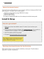
How do I get started?
1. Make sure you have Java installed, version 7.0 or later. (If you're not sure, go to
java.com).
2. Download Command Center for Windows from solartechnology.com. (If you need to run
Command Center on an Apple or Linux computer, contact customer service.)
3. Open the installer and follow the prompts.
4. Proceed to Running Command Center for the first time.
Tip: Supported assets include SolarTech arrow
boards, traffic cameras, and message boards
that run TRAFIX 2.7.3 or later.
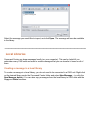
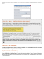
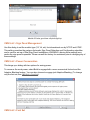
Running Command Center for the first time
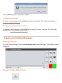
Start Command Center, and log in with the credentials you were given. This will include an
organization, username, and password:
Logging in
Check the box to remember this login for next time, if desired.
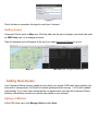
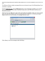
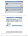
Getting around
Command Center opens in Map view. Click the tabs near the top to change to an Asset view such
as CMS Units view, or to manage accounts.
Tabs for individual units will appear at the top if you select Advanced Control for a unit.
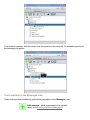
Map view
CMS Units view, one type of Asset view
Adding New Assets
Your Command Center account needs to know about your assets (CMS units, arrow boards, etc)
to be able to manage them. All SolarTech assets purchased after January 1, 2014 will be added
automatically. If you have other assets that do not appear when you start the Command Center
software, follow these directions to add the new assets to your account.
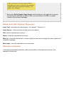
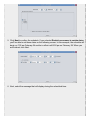
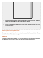
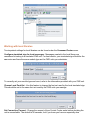
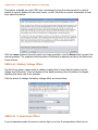
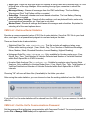
Adding a CMS Unit
In the CMS Units view, click Manage Units and then New.
Adding a new unit
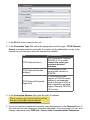
1. In the ID field, enter a name for the unit.
2. In the Connection Type field, select the appropriate connection type. TCP/IP Network
Secure is recommended for most units. If in doubt, use the table below, or refer to the
instructions you were given when the unit was first installed.
Use...
TCP/IP Network Secure
TCP/IP Network Standard
(Multiport)
TCP/IP Network Enhanced
(Single Port)
For connection...
All IP connections. Requires
TRAFIX© 2.1.0 or newer.
Choose this unless you
have been directed
otherwise.
IP connections to units
running older versions of
TRAFIX©
IP connections to older
versions of TRAFIX© where
Multiport is not supported
(such as through a VPN), or
when indicated by technical
support. Requires TRAFIX©
1.9.0 or later.
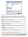
3. In the Connection Address field, enter the unit's IP address.
Tip: If needed, refer to the instructions below,
How do I find a CMS unit's IP address?
4. If your unit requires a password for access, enter that password in the Password field. (If
your unit does not use a password, leave this field blank.) Once connected, you can set or
change a password under CMS Unit > Set the Units Communications Passphrase.
5. In the Description field, describe the unit for easy identification. This field is searchable, so
choose a description that will help you as you are managing units, such as its location or
purpose.
6. If the unit is in a permanent location, you can set it here (for example, a sign that is installed
on a bridge or building.) Otherwise, leave Location unchecked, and the unit's GPS will keep
its location up to date.
7. Click OK to finish. Repeat these steps to add additional units.
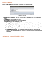
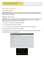
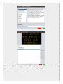
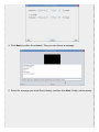
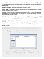
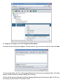
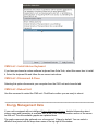
How do I find a CMS Unit's IP Address?
Note: You'll need physical access to the unit.
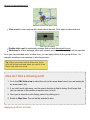
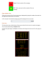
1. Log in to the CMS unit, powering it on first if necessary. (The main power switch is located
on the Energy Management System.) Touch the Information button at the bottom of the
screen. 2. On the Information screen (shown above), locate the IP Address assigned to the unit.
This will include four numbers separated by dots (example: 192.168.1.2). You will need
this IP Address to add a new unit in Command Center. When finished, touch the Log Out
button.
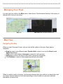
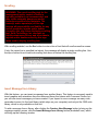
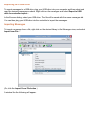
Managing Your Fleet
You can view your units on the Map view or Asset views. Click the tabs at the top of the screen to
change which view you are using.
Map view
CMS Units view, one type of Asset view
Map View
Navigating the Map
When you start Command Center, all your units will be visible on the map. Some tips for
navigation:
Drag the map to view different areas. Double click to zoom in (or use the Zoom In and
Zoom Out buttons).
Click a unit to view details; click again to select it (it will turn blue).
Shiftdrag to select units next to each other (a blue box will appear).
Click Recenter to return to the original map with all units visible.
Selected units are indicated in blue.
When you select a unit on the map, it will remain selected when you switch to an asset view, and
viceversa. Use this feature to find units depending on their location (in map view) and their
description (in asset view).
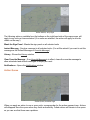
Selected units (including those you've selected in another view, such as CMS Units view) are
shown in blue. Otherwise, the color of each asset on the map indicates its status: green for normal
operations, yellow for a warning or if an override message is in effect, red for a problem, and gray if
the sign is blank.
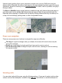
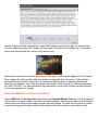
The Map and Satellite buttons toggle between a traditional map, with features like roads drawn in
and color coded, and a satellite view that provides an image of what the area actually looks like.
Especially when zooming in, Satellite view can help by showing features that may not show up on
a map, such as buildings, parking areas, or other recognizable terrain.
Map
Satellite
Power user navigation
There are some poweruser functions to navigate the map more efficiently:
Ctrldrag for a green rectangle; when you release, the screen will zoom to show only the
area in the rectangle.
Scroll your mouse wheel or touch pad (if you have one) to zoom in and out.
Use the Recenter button to bring all of your units into view, zooming out and recentering
the map as needed.
Navigation buttons, at right
Selecting units
You can select units with the map, using the following actions. (If you want to select units by other
criteria, such as their description, consider using CMS Unit view instead, or use the techniques in
How do I find a missing unit?)
Selected units are indicated in blue
Click a unit to view a popup with details about that unit. Click again to select that unit.
Click a unit for details
Doubleclick a unit to individually manage that unit with Advanced Control.
Shiftdrag for a blue rectangle; when you release, any units in the rectangle will be selected.
Once you have selected units, in either view, you can apply actions to the group of them for
example, sending a new message to all selected units.
Tip: When you select units in Map view, those
units will remain selected when you switch to an
Asset view and viceversa.
How do I find a missing unit?
1. Go to the CMS Units view to select the unit (or the arrow board view if you are looking for
an arrow board, etc).
2. If you don't see it right away, use the search function to find its listing. Don't forget that
you can choose to view active or inactive units, or both.
3. Once you've found the unit's listing, select it by clicking on it.
4. Switch to Map View. The unit will be selected in blue.
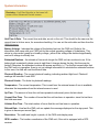
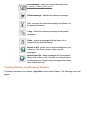
Applying Actions to Units
Action buttons, at top right
The following actions, available from the buttons on the righthand side of the map screen, will
apply to any units you have selected. (If no units are selected, the action will apply to all units
visible on the map.)
Blank the Sign Panel Blanks the sign panel on all selected units
Instant Message Sends a message to all selected units. (You will be asked if you want to set this
message as the Default Message or Override Message.)
Library Shows the Library window.
Clear Override Message If an Override Message is in effect, clears the override message to
allow scheduled and default messages to display as usual.
Notifications Opens the Notifications window.
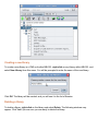
Action Queue
Action Queue, at bottom right
When you apply an action to one or more units, a progress bar for the action appears here. Actions
will disappear from the queue when they finish successfully. Failed actions will remain in the queue
so you can see that there was a problem.
The queue shows actions in progress (blue), and those that have failed (red).
Successful actions appear briefly in green, and then disappear.
Action Detail Window
Click an action in the queue to view the Action Detail Window for details on whether the action has
succeeded, failed, or is in progress on each unit:
Action detail window, showing Continue and Stop buttons.
Depending on the status of the action, the following buttons may be available:
Click Stop to stop the action (available if the action is still in progress).
Click Retry to retry the action (available if the action has failed on any units).
Click Clear to clear the action from the queue (available when the action has finished on all
units).
Click Continue to close this window while leaving the action in progress.
Asset Views
There is a view for each type of asset in your fleet, such as CMS units, arrow boards, etc. (All
types of asset are visible in the Map View). Each asset view contains actions and settings that
make sense for that type of asset.
CMS Units
The CMS Units tab includes features and functions for managing changeable message signs
("message boards").
Compact vs Expanded Views
How much detail would you like to see about each message board? To keep it short and sweet,
choose Compact View. For more information, choose Expanded View. (You can toggle between
them with the buttons at the top of the screen.) Here is the difference:
Compact and Expanded View
Compact view
Expanded view
Both views show:
The unit's name
Unit status (shown in green for normal, yellow when warnings or special conditions are in
effect, and red if there is a problem)
Title of the message currently showing (hover your mouse here for a preview)
Battery voltage, color coded (green for normal, yellow when low, red when critical)
Expanded view shows everything in Compact View, plus an extra row of information:
Description of board (under name)
Photocell readings and temperature (under status)
Uptime (time since unit was last rebooted, given in days)
Runtime (total number of hours the unit has been in operation, since the run timer was last
reset)
"Sparkline" showing battery voltage over time. Some variation is normal, but you don't want
to see a downward trend.
Selecting and Filtering CMS Units
As in Map View, actions apply to selected units, or if no units are selected, they apply to all units
that you can see on your screen.
Click a unit to select it.
Controlclick to select multiple units.
Active and Inactive Units
Active units are the ones that your organization currently uses; inactive units are ones that have
been retired, sold, or otherwise are not in use. Command Center still remembers them for history
and logging purposes.
In an Asset view, only Active units are shown by default; click the All Units button to see inactive
units as well.
Library
The Library window shows the messages in your organization's Library. Click the Library button
(on the righthand side of any Asset or Map view) to open and close the Library window.
The library window shows messages in your organization's library, while also leaving units visible.
Click a message to select it. A preview of the message appears at the top of the library window.
(You can only select one message at a time.)
Selecting messages in the Library window
Activate
sends that message to all selected units (or to all units currently visible on your screen, if none are
selected). You will be asked if you want to set this message as the Default Message or Override
Message.
New
creates a new message.
Edit
opens the selected message for editing.
Delete
deletes the selected message.
How do I change the message on a board?
Using an existing message
1. Select the unit(s) you want to display the new message.
2. Click the Library button.
3. In the Library pane, select the message you'd like to display.
4. Click Activate.
Clicking the Library button shows available messages for selected units, which you can preview and
activate.
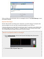
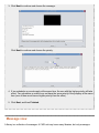
Creating a new message in a hurry (text only)
1. Select the unit(s) you want to display the new message.
2. Click the Instant Message button.
3. Type to create the new message. When you're done, click the green smiley face.
4. Decide if you want to set this as the Override message (it will display no matter what) or
as a Default message (to be displayed only when, for example, previously scheduled
messages aren't in effect.)
Creating a new message.
Each black rectangle is one page of the message.
Notifications
Notifications can be sent whenever some aspect of a unit's status changes: for example, when the
unit is moved, or when an error is detected. Notifications are sent to your email address, which you
can set or change in the Accounts tab.
All Units Notifications
Use this button to configure notifications for all units. You can select which events you want to
receive notifications for:
Notifications for specific units
Click the Notifications button (on the righthand side of any Asset or Map view) to open and close
the Notifications window.
Sliders show notification settings at a glance.
This window shows whether notifications apply to the boards that are selected (or all visible boards
if none are selected). You can switch between On/Off using the slider; if the slider is set at ``Some''
it means that notifications are currently on for some of the units you have selected, but off for
others.
Accounts and Permissions
Different people at your organization can have different permissions for example, some users
may only be allowed to change messages on certain boards, while others may be able to add new
accounts and change others' permissions.
You can authorize other people to manage some or all of your organization's assets. You'll do this
from the Accounts tab.
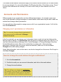
Changing users' permissions or information
Tip: You can only change others' permissions if
your own account is authorized for Manage
Units & Accounts
In the Accounts tab, you can change users' information (name, email, etc) just by clicking on the
field you want to change. The Permissions field will become a dropdown when you click on it. If a
user has limited permissions (Manage Units, Create Messages, or Change Messages Only) then
the last field will have a link. Click on it to restrict them to certain units. (Users who have
permission to Manage Units & Accounts cannot be restricted.) Make sure to click the Save
Changes button after making changes.
Users' other information, such as their name, can also be changed from this screen. Don't forget to
click Save Changes.
How do I change the email address that gets notifications?
1. Go to the Accounts tab.
2. Find the line with your own account information, and click on the email address.
3. Change the email address.
Tip:The settings you choose for notifications
(for example, from the CMS Units screen) apply
only to your account. Each user can set their
own email address and notification preferences.
Creating a New User
Click the Create New button. Here's the information you'll need to provide:
Creating a new user
Username and Password: The user will use these to log in, along with your organization
name.
Full Name: So you remember who this is.
Email address: Where they will receive notifications.
Permissions: What they are allowed to do:
Manage Units & Accounts: All permissions (including deleting accounts such as your
own!) This is obviously for trusted users only.
Manage Units: Users with this permission can do all unit management tasks (including
everything in Advanced Control).
Create Messages: Users with this permission can change and create messages, but
won't be able to change settings or other advanced tasks.
Change Messages Only: This is the lowest level of permissions; these users can
change a sign's message to another message in the library, but can't create their own
messages.
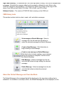
Advanced Control for CMS Units
Features of the Advanced Control Screen
1. Current Message Screen shows the message that is currently displayed on the CMS Unit's
sign panel (amber color).
2. CMS Schedule calendar for scheduling messages. Create timebased or eventbased
schedules with the tools in this section.
3. CMS Information and tools provides information about the CMS unit, including status of
hardware components, and version of software.
If your unit includes an intelligent Energy Management System, there will be a link here to view
advanced Energy Management Data
If your unit includes a GPS, there will be a map_it link here to view the unit's location in your
browser. (However, you can also view this unit in Map View without leaving Command Center.)
4. Quick Functions buttons for common actions. Read about Quick Functions.
5. Preview Message Screen shows messages in the library as you select them (blue color).
6. CMS Library Toolbar use this to select, create, and edit messages.
7. CMS Library shows all messages available in the CMS unit's Working Library
8. Status bar shows progress of operations (left) and link quality (right). A link quality of 10 is
ideal. Lower link qualities indicate a slower connection between your computer and the sign (but
the connection will still work). If you are using a secure connection, a padlock icon will be shown in
the status bar.
CMS Unit Status Information
In the lower left hand corner of the CMS unit screen (item 3, above), status information is available.
This information may be useful in managing and monitoring the unit.
Sign Status Whether the sign is running properly. This notification appears in green if the sign
status is Normal, orange for Sign Panel Blanked, and red for serious errors, such as an LED
module failure. The status is updated every 60 seconds.
Now Displaying the name of the message that is currently being displayed on the units sign
panel. This information is updated whenever the message changes.
Default Message the name of the Default Message. This is the message that will be displayed
when no schedules or events are in effect. This information is updated whenever the Default
Message changes.
Last Updated the time the information on this screen was last updated. Click the Update System
Status button to update the information.
Quick Functions
Blank the Sign Panel Blanks the sign panel.
Instant Message Creates a new message and sets it as the Default Message. (Same as Create
New Message as Default Message button in the library toolbar.) When you create a message with
this button, it will be named Instant Message.
Update System Status Updates the system status information shown on this screen.
Get Radar Statistics Provides commaseparated values (CSV) files of recorded radar statistics.
Save these CSV files to your hard drive, and open them in a spreadsheet program (or with an
appropriate analysis software package such as Houston Radar's Stats Analyzer) to read and
analyze the data.
Disconnect Disconnects from this unit.
Close Unit Closes the tab for this unit, returning to the main CMS Units tab.
Clear Override Message If an Override Message is in effect, use this button to remove the
Override Message. This button is only visible when an Override Message is in effect.
System information
Reminder: You'll find this info in the lower left
corner of the Advanced Control screen.
Unit Time & Date The current time and date, as set on the unit. This should be the same as the
current time in its time zone, for accurate scheduling. You can set the units date and time from the
CMS Unit menu.
Battery Voltage Indicates the voltage of the battery bank on the CMS unit. Refer to the
information that came with your CMS unit for the normal operating voltage of its batteries. This
status is colorcoded: green for a healthy voltage, yellow if the voltage has declined significantly,
and red if voltage is critically low.
Estimated Runtime An estimate of how much longer the CMS unit can continue to run. If the
battery bank consistently drains more at night than it charges during the day, this time may be
limited. Otherwise, the estimated runtime will appear as infinity (∞). For the first several days that
the CMS unit is in operation, there is not yet enough information to calculate the estimated runtime.
In this case, the field will read Insufficient data.
Photocell Reading The current photocell reading, indicating ambient light level. Photocell
readings fall between 0 and 4000.
Photocell Limits The limits for photocell readings.
Temperature The current temperature. This is read from the external sensor if one is available;
otherwise the temperature from the internal sensor is used.
UpTime The amount of time this unit has operated continuously since its last reboot.
Current RunTime The number of hours that the unit has been in operation, since the last time
this field was reset.
Lifetime RunTime The total number of hours that the unit has been in operation.
Refresh Rate How fast the CMS unit can update the message displayed on the sign panel. This
is given in frames per second (fps).
Resolution The width and height, in pixels, of the CMS units display area.
GPS Location The location coordinates of the CMS unit, if the unit is equipped with a GPS
receiver.
Sign Panel Heading The direction the CMS units sign panel is facing, if the unit is equipped with
a compass. (Note that the compass offset must be properly calibrated onsite. Refer to the
TRAFIX© manual for this procedure.) The direction is given as a number in the range 0360,
where 0 and 360 are both North, 90 is East, 180 is South, and 270 is West.
Software Version The version of TRAFIX© that is running on the CMS unit.
CMS library tools
This section includes tools to select, create, edit, and delete messages.
Set message as Default Message Select a
message from the list and click this button to
make the selected message the Default Message.
Create a New Message Click this button to
begin creating a new message.
Create a new message as Default Message
Click this button to begin creating a new message.
When the message is complete, it will be set as
the Default Message.
Edit Message Select a message from the list
and click this button to begin editing the selected
message.
Delete Message Select a message from the list
and click this button to delete the selected
message.
About the Default Message and Override Mode
The Default Message is the message that will be displayed on the sign when nothing else is
scheduled. If a schedule is currently in effect, the Default Message will not be displayed, on the
sign panel or on the Current Message Screen, until the schedule has completed.
If a schedule is in effect when you set a message as the Default Message (either with the check
plus button, the check button, or the Instant Message button), you will see this dialog:
To display the message in place of any scheduled messages, click Set as Override. To allow the
schedules to continue, and have the new message as a Default Message only, click Set as
Default.
For more information on scheduling messages, see Schedules and Events.
Common Tasks
Previewing a message
To preview a message without displaying it on the sign, select the message from the message list.
It will display, in blue, on the Preview Message Screen.
Changing the message that displays on the CMS unit
Select the message from the message list, and click the Default button (yellow checkmark). The
message will be set as the Default Message and as long as no schedule is in effect, the message
will be displayed on the CMS unit's sign panel and on the Current Message Screen.
Creating and displaying a new message
Click the Create a new message as Default Message button (checkmark/plus) to begin creating a
new message. When the message is created, it will become the Default Message and as long as
no schedule is in effect, the message will be displayed on the CMS unit's sign panel and on the
Current Message Screen.
Deleting a message
To delete a message, select the message from the message list and click the Delete button (black
X). You will see this warning:
Click the Delete button to confirm the deletion.
Creating a new message
To create a new message, click the New button (green plus sign). Then follow the directions in
Creating and Editing Messages.
Changing a message that already exists
To change or edit a message, click the Edit button (pencil, scissors, and glue). Then follow the
directions in Creating and Editing Messages.
Creating and Editing Messages
Creating messages
To create a new message, click the new message button (green plus sign). The following window
will appear:
Message Creation/Editing Tools
Copy Creates a duplicate of the current page.
Insert text page Inserts a new text page in the
message.
Create graphic page Allows you to create a graphic
image and insert that image as a page into the
message.
Insert dynamic data page Inserts a page with
dynamic data such as temperature, time, radar, etc.
Insert message from library Inserts a message
from another library.
Delete page from message Deletes the current
page (selected with red border) from the message.
Move page left Moves the currently selected page
to the left (earlier in the message).
Move page right Moves the currently selected page
to the right (later in the message).
Fx Special effects: activate signal lights, flash page,
or apply line effects such as moving arrows and
chevrons.
Scr Scrolling (Not recommended for road safety
applications) enter a scrolling message.
Cancel Aborts creation of the message.
OK Finish, name and confirm creation of the new
message.
Page display time
Change the amount of time the message page is displayed by typing the number of seconds into
this input area at the bottom of the screen:
In this example, the selected message page will be displayed for two seconds.
Font size
The dropdown menu at the bottom of this screen selects the font size to be used in text pages.
The recommended setting is Adaptive Text.
As typed text gets longer, the Adaptive Text feature will change the font size to fit on the page, as
shown:
Adaptive Text is the recommended setting, but if you need a particular size of font, choose it from
the menu at the bottom of the screen:
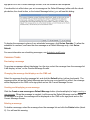
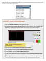
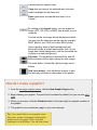
How do I create a new message?
1. Click the Create New Message button (green plus sign).
2. When the Message Creation Window appears (as shown above), click the Insert Text
Page button. A blank text page will appear, with a cursor in the middle, as shown:
Note: The page you are working on is
outlined in red.
3. Type the text you want to appear in this page of the message.
4. To add another text page, click the Insert Text Page button again.
5. To add a graphic, click the Create Graphic Page button.
6. To add dynamic data such as time or temperature, click the Insert Dynamic Data Page
button.
7. Click the OK (smiley face button) when finished. After naming and saving the new
message, it will be available in the CMS Library screen.
Creating a graphic
To create a graphic in your message, click the Create Graphic Page button within the Message
Creation Screen. A window like the following will appear.
Tip: The box at the top of the graphics editing
screen shows a smaller version of your graphic
(as it would look from a distance).
Graphics Editing Tools
Selection tool allows you to make rectangular
selections. Use this with the Cut, Copy, and Paste
tools, or the Flip tools (see below). To stop selecting
an area, click anywhere outside the selection.
Pencil tool use this to draw freehand. Holding down
the Shift key on your keyboard allows you to quickly
draw lines with this tool.
Line tool To draw lines, click at the position you
would like to start, then select the Line tool. A white
guideline will appear starting at the position of your last
click. Click again at the desired endpoint to create the
line.
Circle tool To draw circles, select the Circle tool and
click where you would like the center of your circle to
be. Hold the mouse button down. As you drag the
pointer away from the center, a guide circle will
appear. Release the mouse button when the circle is
the desired size.
Text tool To add text to your graphic, select the Text
tool and then click where you would like the text to
begin. Type the text, select the desired font size, and
click Draw. The text will be added to the graphic, inside
of a rectangular selection that can be dragged into
place.
Pixel Selection The default behavior is to draw lit
pixels. To erase, change to dark pixels. All of the
above tools work with dark as well as lit pixels.
Brush Selection Select the desired size to draw thin,
medium, or thick sized lines with the Pencil or Line
tools.
Undo and Redo After completing an action (such as
drawing a line), the Undo button, shown here at top,
will become available. Click Undo to undo an action.
After you have undone an action, the Redo button
will be available, should you choose to redo that
action.
Cut, Copy, and Paste To use these tools, make a
selection with the Selection tool (described above).
Cut removes the selected area.
Copy does not remove the selected area, but does
make it available for the Paste tool.
Paste reproduces an area that has been Cut or
Copied.
By clicking on the Import button, you can import an
image (JPG, GIF, PNG, or BMP) from a folder on your
computer.
For best results, the image should be black and white
(no gray) and the same size as the sign (for example,
48x27 pixels if your CMS unit is also 48x27 pixels).
Upon importing, white or light colored pixels will
become lit pixels, and dark pixels will be unlit. (If your
image has a white background, it will be converted into
lit pixels on a dark background.)
Flip tools The top button is Horizontal flip, and will
flip the selection lefttoright (making a mirror image).
The lower button, Vertical flip, flips the image topto
bottom.
Grid Lines button click this button to show or hide
the faint gray grid lines on dark areas of the graphic.
How do I create a graphic?
1. From the message creation screen, click the New Graphic Page button.
2. Begin drawing your graphic. The pencil tool is selected by default, but you can use other
tools.
3. When you are done, click the Finished button (in the lower right) to complete creation of
the graphic.
4. The graphic is now created as a page in your new message.
Tip: If you would like to use a graphic more
than once, create a message containing the
graphic as its only page. Then, save this
message in a local library. You can then insert
the graphic page into other messages with the
Insert message from library button.
Special Effects (Fx button)
The special effects include:
Activate Signal Lights turns on the signal lights while this message is being displayed. Signal
lights, present on some CMS units, are extra lights attached to the sides of the message board to
draw attention to the message.
Flash Page flashes the page
Line Effects When using a fixed font (not compatible with Adaptive Text) you can apply effects to
each line of a message: flashing the line, arrows, moving arrows, and chevrons. Arrows and
chevrons replace any text you have entered for that line.
> is a static (nonmoving) arrow that points to the right.
> > is a moving arrow that points to the right.
> > > > is a series of chevrons pointing to the right. The chevrons appear onebyone.
(Leftpointing arrows and chevrons are also available.)
The example below shows a three line message. The first two lines are text, and use a flashing
effect; the third line is a moving right arrow.
Scrolling
WARNING: The use of scrolling text for the
management and/or control of traffic is
typically prohibited, not recommended, and
may create extremely dangerous and/or
hazardous conditions for motorists. The
owner(s) and/or operator(s) of this sign
assume all responsibility and liability for any
and all accidents, injuries and/or deaths
caused by this sign when displaying scrolling
text. Solar Technology, Inc. assumes no
liability whatsoever for any and all accidents,
injuries and/or deaths caused by this sign
when used to display scrolling text.
With scrolling enabled, use the Scr button to enter a line of text that will scroll across the screen.
If only the center line is specified (as below), the message will display a single scrolling line. Use
the top or bottom lines to add nonscrolling text above or below the scrolling line.
Insert Message from Library
With this feature, you can insert a message from another library. This feature is commonly used to
insert graphics and animations from the reference library that comes with Command Center, but
you can also insert messages you have created. If you expect to use a message on many units,
remember to save it in the local library (which stays on your computer) and not just the CMS units
library, which is only available on that unit.
To add a message from a library, after clicking the Create a New Message button to bring up the
message creation screen, click the Insert Message from Library button (bookshelf icon), which
will bring up the following window:
Click on a folder to open that folder; click on a message to select it. Click Select Message to insert
the selected message.
Dynamic Data Pages
Dynamic data includes such things as time, temperature, and radar readings. The dynamic data
sources available to you will vary with the equipment available on your CMS unit.
A dynamic data page can include both text and dynamic data. For example, a page displaying the
time might include the words "The time is ", followed by the time. When editing a dynamic page,
use the Insert Source and Insert Text buttons to build the message.
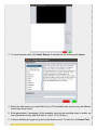
How do I use dynamic data in a message?
1. When creating a message, click the Insert Dynamic Data Page button (thermometer
image).
2. You'll see the Edit a Dynamic Page screen:
3. To insert dynamic data, click Insert Source. A window like the following will appear.
4. Select the data source you would like to use. (The available data sources may be different
from those shown here.) 5. Enter parameters, if necessary. In this example, since we are counting down to a date, we
use a parameter to say what that date is (July 4, 2014, at 9pm.) 6. Continue building the page using text and/or data sources. To add text, click Insert Text.
Tip: Remember to include spaces before
and after your text, so that the text and data
reading will not be squished together. ("10
days", not "10days")
7. Back at the Edit a Dynamic Page Screen, use the buttons on the right side to arrange
and edit the text and data as desired. When you are finished, click OK to complete
creation of the dynamic data page.
Buttons in the Edit a Dynamic Page screen
Insert Text insert plain text (non dynamic for example, "The time is ".)
Insert Source choose and insert a data source (see below).
Edit edit the selected text or source.
Delete delete the selected text or source.
Move up move the selected text or source up (this can be used to change the order of portions of
a dynamic message).
Move down move the selected text or source down.
Data source parameters
A few data sources take parameters, which are described on the data source screen. One
example is shown here:
The data sources that take parameters include the following:
DaysSince Counts the number of days since a specified date. (Example use: It has been __
days since the last accident). To provide the date, enter it in the parameters field in the format
DATE=MM/DD/YYYY. In our example, if the last accident was on December 3, 2009, the parameter
would be DATE=12/03/2009 .
DaysUntil Counts the number of days until a specified date. (Example use: Road work begins in
__ days). Use the same date format as above.
Weekday Displays the current weekday, but requires a parameter for the language. To display
the weekday in French, for example, set this parameter to language=french.
Wkdy Displays an abbreviation for the name of the weekday (for example, Mon for Monday). It
takes a language parameter as above.
CountdownDays Like DaysUntil, but counts down to a specific date and time in the format
DATE=MM/DD/YYYY:hh:mm. Designed to be used with CountdownHours and CountdownMinutes (see
example below).
CountdownHours Counts down the hours until a given date and time. Designed to be used with
CountdownDays, and uses the same date format.
CountdownMinutes Counts down the minutes until a given date and time. Designed to be used
with CountdownDays and CountdownHours, and uses the same date format.
How do I display a countdown to an event?
1. To count down to a fireworks display on July 4, 2014, at 9:00pm, create a dynamic message
using CountdownDays, CountdownHours, and CountdownMinutes all with a parameter of
DATE=07/04/2014:21:00 At noon on July 3, this message would read "Fireworks begin in 1 day 9 hours and 0 minutes."
2. To count down to a day without specifying a time, use DaysUntil:
Schedules and Events
Schedules can be used to display a message at a particular date and time. Similarly, a datadriven
event can be used to display a message when a certain event occurs (for example, a radar reading
above a certain speed).
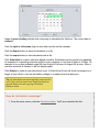
The calendar on the left side of the main screen shows the current date along with any timebased
schedules that may be in effect. In the example below, the current date is the 24th and there is a
schedule in effect part of each day from today until Sunday.
Areas of green shading indicate that a message is scheduled for that time. The current date is
outlined.
Click the right or left arrows (top) to view other months on the calendar.
Click the Export button to save all schedules to a file.
Click the Import button to load schedules from a file.
Click Schedules to create a new timebased schedule. Schedules can be onetime or repeating.
An example of a repeating schedule might be every weekday in July from 9:00am to 5:00pm. An
example of a onetime schedule might be from August 28 at noon to August 29 at noon. After a
onetime schedule is finished, it will not display again.
Click Events to create a new datadriven event. A DataDriven Event will show a message on a
trigger of your choice, such as low battery voltage or a reading from the radar gun.
Tip: All schedules are automatically saved on the
unit. Only use the Import and Export buttons for
special tasks such as copying schedules
between units.
How do I schedule a message?
1. From the main screen, click the Schedules button. You'll see a window like this. 2. Click the Add button to add a new schedule. Select Onetime schedule and then click
Next.
3. In the next screen, indicate when you would like the message to be displayed. In this
example, the message will be displayed from 7:00 am November 14 until 5:00 pm on
November 20.
4. Click Next to confirm the schedule. Then you can choose a message: 5. Select the message you would like to display, and then click Next. Finally, set the priority: 6. If two schedules or events apply at the same time, the one with the higher priority will take
effect. Two schedules or events may not have the same priority if they display at the same
time (one of them must higher priority than the other).
7. Click Next, and then Finished.
How do I schedule a repeating message?
A repeating message is a type of scheduled message that has the ability to turn on and off on a
regular basis: for example, a message that only displays during the evening rush hour.
1. To begin, click the Schedules button from the main screen, click Add, choose Repeating
Schedule, and click Next. 2. In the next screen, give a start and end date for the schedule.
3. 4. In the next screen, indicate when you would like the message to be displayed. You can
give a start or stop time, and the type of repeat (daily, weekly, monthly). In this example,
the message will be displayed from 7:00 am until 5:00 pm.
If you want the schedule to only apply during a certain time period (for example, during a
road work project), check the box for Restrict recurrence to certain dates and on the
next screen you can set start and end dates.
5. Click Next to confirm the schedule. If you selected Restrict recurrence to certain dates,
you'll be able to set those dates on the following screen. In this example, the schedule will
begin on 7:00 am February 24 and be in effect until 5:00 pm on February 28. When you
are finished, click Next.
6. Next, select the message that will display during the scheduled time:
7. Finally, set the priority:
8. If two schedules or events apply at the same time, the one with the higher priority will take
effect. Two schedules or events may not have the same priority if they display at the same
time (one of them must higher priority than the other).
9. Click Next, and then Finished.
Data sources for events
Events can be based on data from different equipment that might be part of or connected to your
unit. Commonly used sources include the following:
Battery Voltage in tenths of a volt. A reading below 110 (11.0 volts) typically indicates very low
battery power. Your particular battery may vary.
ExtTempC, ExtTempF If your CMS unit is equipped with an external temperature sensor, these
sources will provide readings from it in degrees Celsius (ExtTempC) or Fahrenheit (ExtTempF).
The external sensor is typically more accurate than an internal sensor. See also the TempC and
TempF sources.
IntTempC, IntTempF Temperature readings from the internal sensor.
TempC, TempF These sources read the temperature from an external sensor if one is available,
and from the internal sensor if it is not.
PhotoCell The raw photocell reading, which may range from 04000. In typical conditions, this
reading is below 400 at night and above 3000 during the day. Location, light pollution, and other
conditions may all affect this reading.
Radar The radar gun reading. This may be in miles per hour (MPH) or kilometers per hour (KPH)
depending on how your radar gun is configured. To change the units, go to the CMS Unit menu
from the main screen and select Set Radar Units.
SwitchClosure1 SwitchClosure6 Use these sources for custombuilt equipment. (See the
TRAFIX© manual for information on connecting and using this type of equipment). The source will
read 1 when the switch is closed and 0 when it is open. To display a message when the switch is
closed, for example, set both the maximum and minimum values to 1. There may be up to six
switches available.
How do I trigger a message from data such as radar gun readings?
1. From the main screen, click the Events button, then click Add to add a new datadriven
event. The following window will appear: 2. Select the data source you'd like to use on the left side of the screen, then set minimum
and maximum values. In this example, our message will be displayed when the radar
reading is between 45 and 100 mph. (See Data Sources for Events to learn more about
these settings.)
3. Click Next to continue and choose the message: Click Next to continue and choose the priority.
4. If two schedules or events apply at the same time, the one with the higher priority will take
effect. Two schedules or events may not have the same priority if they display at the same
time (one of them must have a higher priority than the other). 5. Click Next, and then Finished.
Message view
A library is a collection of messages. A CMS unit may have many libraries, but only messages
from the Working library (and a special library called Quick Picks) are available for use on the CMS
unit.
The Reference library contains messages that you can choose to copy to the Working library if you
would like to use them.
From the CMS Units view, click the Messages button to see the libraries available to you, both on
your computer (shown as the folder Command Center) and on all CMS units to which you are
currently connected.
Click the name of a CMS unit to open it and view the libraries available on that unit. In the example
below, the unit called MB001 has the two standard libraries: Reference, containing messages
shipped with the unit, and Working, for messages that you create.
Click a library to view the messages inside that library.
To preview a message, hold the cursor over its name for a few seconds. An animated preview of
the message will appear:
Tools available in the Messages view
These tools are also available by rightclicking anywhere in the Messages view.
Add message adds a message to the selected
library (see Creating and Editing Messages).
Edit message edits the selected message (see
Creating and Editing Messages).
Delete message deletes the selected message.
Cut removes the selected message and allows it to
be pasted elsewhere.
Copy allows the selected message to be pasted
elsewhere.
Paste inserts a message that has been cut or
copied into the selected library.
Export to file saves one or more messages to your
computer. Use this to share or back up your
messages.
Import from file loads messages into the selected
library from a file on disk. Use this to restore backed
up messages or to begin using messages that others
have shared with you.
Creating, Deleting, and Renaming Libraries
To perform operations on a library, rightclick on the desired library. The following menu will
appear. Creating a new library
To create a new library in a CMS unit called MB001, rightclick on any library within MB001, and
select New Library from this menu. You will be prompted to enter the name of the new library.
Click OK. The library will be created, and you will see it in the list of libraries.
Deleting a library
To delete a library, rightclick on the library and select Delete. The following windows may
appear. Click Yes if you are sure you are ready to delete the library.
Renaming a library
To rename a library, click on the librarys name, and then click on it a second time. The librarys
name will change to an editable text box.
Type the library's new name in this box, and then click outside of the box (in any blank space on
the screen) to finish the renaming process.
How do I move a message from one sign to another?
The Messages view also allows you to move messages and libraries between CMS units. In this
example, we will copy a message called "buckle up" from the Command Center Library to the
Working Library on the CMS unit called MB001.
Tip: When copying or moving messages
between CMS units of different sizes,
messages will be resized to fit the new CMS
unit if possible. Be sure to preview the
messages after copying to be sure they display
the way you expect.
1. First, rightclick on the message you would like to copy, and select Copy.
2. Then, rightclick on the library you would like to copy the message to, and select Paste.
3. To copy the message into other libraries (for example, on multiple CMS units), Copy the
message once and Paste it into each of the destination libraries.
4. To move a message without duplicating it, simply Cut the message and then Paste it into
the destination library.
Exporting and Importing Messages
Messages can be exported (saved to a file) and can be imported into Command Center. This can
be useful to share or back up your messages.
Exporting
To export a message (save a message to a file on your computer), select the desired messages
and Copy them with the button or menu. Then rightclick and select Export to File... Or, Copy the messages and click the Export to File button.
A window like the following will appear. Choose a folder, type in a name for the file, and click Save.
In the example above, the file is being named Buckle Up in the saved_messages folder. The folder
already contains another message called Deer Crossing.
The file will be saved as the type SolarTech Message Bundle with the extension .stb. This file can
be used by any other user of Command Center.
Exporting to a USB drive
To export messages to a USB drive, plug your USB drive into your computer and then select and
copy the desired messages as above. Rightclick on the messages and select Export to USB
drive for controller import....
In the file save dialog, select your USB drive. The file will be saved with the name messages.stb.
You can then plug your USB drive into the controller to import the messages.
Importing Messages
To import a message from a file, rightclick on the desired library in the Messages view, and select
Import from File....
(Or, click the Import From File button.)
A window like the following will appear:
Select the message you would like to import, and click Open. The message will now be available
in the library.
Local Libraries
Command Center can keep messages locally (on your computer). This can be helpful if you
administer many CMS units and want to create messages that you can transfer to some or all of
them.
Creating a message in a local library
To create a message in a local library, you do not need to be connected to a CMS unit. Rightclick
on the desired library under the Command Center folder and select New Message... (or click the
New Message button). You can also copy messages from the local library to CMS units with the
Copy and Paste functions.
Working with local libraries
Two important settings for local libraries can be found under the Command Center menu.
Configure simulated sign for local messages Messages created in the local library are
considered to belong to a simulated CMS unit. For best results, your simulated sign should be the
same size and have the same module type as the CMS units you administer.
To correctly set your module type and count, refer to the information provided with your CMS unit.
Choose Local FontSet Use this feature to change the font set used by the local simulated sign.
This should be set to the same font set used by the CMS units you manage.
Set Connection Timeout Change the amount of time Control Center waits before deciding the
unit is unreachable. The default is 90 seconds, but if you know you have an especially slow
connection, use this feature to set a longer timeout.
Set Language Change the language used by Control Center.
Use Background Images Uncheck this option for slightly faster performance, for example if you
access Control Center via remote desktop.
Background Image Select a different background image for the main screen.
Check for Updates Check for updated versions of the Control Center software.
Managing your CMS unit
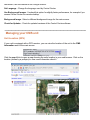
Unit Location (GPS)
If your unit is equipped with a GPS receiver, you can view the location of the unit in the CMS
Information area of the main screen
Click the map it link to open a map showing the units location in your web browser. Click on the
location (shown by a pushpin) to view more information about it.
From this page, you can use any features of Google Maps, such as zooming in and out, or getting
driving directions to the unit.
Energy Management
If your unit is equipped with an Energy Management System (EMS), detailed information about the
unit's energy usage is available by clicking the link in the CMS Information area.
CMS Unit Menu
Under the CMS Unit menu, there are many tools that allow you to manage the unit:
CMS Unit > Manage Quick Picks
On the CMS unit, a Quick Picks menu may contain up to six messages for easy access. Use
Manage Quick Picks to add messages from the active library to Quick Picks, as shown:
To move a message into Quick Picks, select the message in the list on the left, and click the right
arrow button to move it into the Quick Picks list. To remove a message from Quick Picks, select
the message in Quick Picks and click the left arrow button.
CMS Unit > Set Date/Time
Use this to set the date and time on your CMS unit's clock. If your computer's clock is correct, just
click Set Time From This Computer's Clock. Otherwise, set the time manually:
The location listed at the top (here, America/New_York) is a simple way to indicate the time zone;
just choose the city nearest you.
CMS Unit > Set Module Intensity Curve
For closer control over the signs brightness, CMS units with newer module types (V3 HD, V4 HD,
and V6) can respond to an intensity curve. Command Center© comes with several curves
programmed in; you can also create a custom curve.
WARNING: Custom module intensity curves are not recommended and, if used
improperly, may cause extremely dangerous and/or hazardous conditions for
motorists. Custom module intensity curves may render sign illegible during
periods of high ambient light levels and/or may cause sign panel to temporarily
blind motorists during periods of low ambient light levels. The owner(s) and/or
operator(s) of this sign assume all responsibility and liability for any and all
accidents, injuries and/or deaths caused by this sign when operated with a
custom module intensity curve. Solar Technology, Inc. assumes no liability
whatsoever for any and all accidents, injuries and/or deaths caused by this sign
when operated with a custom module intensity curve. Controller will NOT reset the
curve upon a restart.
To use a programmed curve, select it from the menu at the top of the window. Solar Powered, the
default, is appropriate for most installations. Line Powered options are available for high and low
light pollution areas, as well as indoor installations.
To create a custom curve, select Custom from the menu. A window like the following will appear.
Drag the points of the curve as desired. The numbers along the bottom of the chart represent
intensity levels from the photocell, from 1 to 16. The numbers along the side represent LED
brightness, as a percentage of maximum brightness. The higher a point, the brighter the sign will
be at the given intensity. In the example above, at a photocell intensity of 9, the LEDs will operate
at 30% brightness.
CMS Unit > Override Photocell Intensity Control
Photocell limits govern how bright the sign is in response to ambient light level. If the display is not
bright enough, lowering the limits may help. If the sign is too bright, raising the limits may help. For
most signs, the default setting works well.
WARNING: Manual selection of photocell set points is not recommended and, if
used improperly, may cause extremely dangerous and/or hazardous conditions for
motorists. Manual selection of photocell set points may render sign illegible
during periods of high ambient light levels and/or may cause sign panel to
temporarily blind motorists during periods of low ambient light levels. The
owner(s) and/or operator(s) of this sign assume all responsibility and liability for
any and all accidents, injuries and/or deaths caused by this sign when operated
with improperly selected manual photocell set points. Solar Technology, Inc.
assumes no liability whatsoever for any and all accidents, injuries and/or deaths
caused by this sign when operated with improperly selected manual photocell set
points. Controller will automatically restore system to automatic photocell set
point selection and operation upon a restart.
CMS Unit > Solar Array Debris Clearing
This feature, available on some CMS units, will attempt to lower the solar panel into a vertical
position to remove debris such as snow, leaves, or dust. Read the onscreen information to learn
more about this feature.
Click the Lower button to lower the panel into cleaning position, and the Raise button to raise it for
normal operation. The expected current position of the panel is reported just above the Raise and
Lower buttons.
CMS Unit > Battery Voltage Offset
Use this if long power cables result in a battery reading that is lower than the batterys actual
voltage due to line drop. If the unit displays a low battery warning when the battery is charged,
adjusting this offset may fix the problem.
Click the arrows to change the battery voltage offset, as shown below.
CMS Unit > Temperature Offset
If your temperature probe is known to read too high or too low, the temperature offset can be
adjusted to provide a correct reading. Click the arrows to change the temperature offset, as shown
below.
How do I test a malfunctioning sign panel?
Since your sign panel is made of blocks of pixels called modules, it's possible that a pixel fails
(does not light) or that a module fails (does not communicate properly with the rest of the sign).
Command Center includes tools to test the sign in both cases.
These sign tests are meant to be performed
when you can see the unit. Do not perform
them remotely; they won't help.
Pixel failure If a pixel has failed, the sign will still display messages but one or more pixels
aren't functioning. In Command Center, a red box will be shown around the failed pixels in
Advanced Control mode. If you'd like to test the pixel directly, proceed to the Individual Module
Test.
Module failure If a module has failed, the sign will probably be blank and the console will
display a module display failure message. In Command Center, the sign status will read "LED
Module Failure" in red. To figure out which module has the problem, proceed to the Sign Panel
Test.
CMS Unit > Test Sign Panel...
In case of a pixel or module failure, two tests are available. You must be able to see the sign panel
to run these tests; do not perform them remotely.
Sign Panel Test (for module failure)
Select CMS Unit > Test Sign Panel. The test will start automatically. Control Center will attempt to
send the right test pattern for your module type, but if you know your module type, you can choose
it, as shown below:
Control Center will send a test pattern to each LED display module in the sign, as shown below.
The first module that does NOT display the test pattern is likely to be the failed one. (In the photo
below, this would be the 5th module in the second row).
Remove the module in the bottom right corner of the sign, connecting the Bypass Plug in its place.
Then, replace the failed module with the module you removed from the corner. (If the problem
persists, the failed module may be the one before the blank module. If replacing that module
doesn't fix the problem, more than one module has failed. Call the factory for technical assistance
at 18004755442.) You can operate the sign temporarily in this mode, placing the failed module
in the corner position for storage.
Individual Module Test (for pixel failure)
Select CMS Unit > Test Sign Panel and select the Individual Module Test tab. This test lights all
of the pixels on a single module, as shown in the photo below. Use the arrow buttons at the bottom
of the screen to change which module's pixels are being tested. This test can be useful to confirm
a malfunctioning pixel (it will be dark even though the rest of the pixels on the module are lit).
Module 23 looks good here: all pixels light up.
CMS Unit > Sign Panel Management
Use this dialog to set the module type (V3, V4, etc) for informational use by NTCIP and UTMC.
This setting overrides the systems Automatic Sign Panel Detection and Configuration algorithm
and is used for setup of Dual Sign Panel installations. WARNING: altering these settings may
render the sign panel inoperable. Please consult the factory for assistance prior to changing any of
these settings.
CMS Unit > Power Conservation
This brings up a dialog with two options for saving power.
To conserve the most power, select Both to engage both a more economical font set and the
Adaptive Blanking feature. You can also choose to engage just Adaptive Blanking. (To change
only the font set, see CMS Unit > Font Set.)
CMS Unit > Font Set
Use this menu item to change the font set used by the CMS unit.
CMS Unit > NTCIP Control
If this is set to Disabled, NTCIP Central Command cannot be used with this CMS unit. When this
field is set to Enabled and Central, the unit will communicate with NTCIP Central Command and
not be usable with Control Center 3000©. When the field is set to Enabled and Local, Control
Center 3000© can be used, but NTCIP Central Command will be able to take over communication
with the sign. It is only possible to use either Control Center 3000© or NTCIP Central Command to
control the CMS unit at a given time. For more information on using NTCIP with a SolarTech CMS
unit see the SolarTech NTCIP Integration Guide.
CMS Unit > Blanking Between Pages
When set to Automatic, the CMS unit will insert short blanks (less than 1 second) between
message pages if needed to save battery life. When set to On, blanks of 300ms will always be
added. When set to Off, no blanks will be added.
CMS Unit > Dynamic Pixel Failure Detection
Your CMS unit tests itself during operation to make sure all pixels are working properly. (If a failure
is detected, you will see the defective area highlighted with a red box on the main screen). These
tests light up pixels for a few microseconds at a time and are normally not detectable by the human
eye. Note: turning off Dynamic Pixel Failure Detection means that you will not be automatically
notified of dead pixels.
CMS Unit > Scrolling Messages
Enable or disable the ability to scroll text in messages (have it move sideways across the screen).
WARNING: The use of scrolling text for the management and/or control of traffic is typically
prohibited, not recommended, and may create extremely dangerous and/or hazardous conditions
for motorists. The owner(s) and/or operator(s) of this sign assume all responsibility and liability for
any and all accidents, injuries and/or deaths caused by this sign when displaying scrolling text.
Solar Technology, Inc. assumes no liability whatsoever for any and all accidents, injuries and/or
deaths caused by this sign when used to display scrolling text.
CMS Unit > Set Radar Units
Use this menu item to set your radar gun reading to miles per hour (MPH) or kilometers per hour
(KPH).
CMS Unit > System Reset
The options in this submenu will erase certain settings from your CMS unit. Use with caution; this
cannot be undone.
RunTime Counter Resets the runtime counter (the Current RunTime field in CMS
Information). Like a trip odometer, this may be reset at any time. Lifetime RunTime readings
are not affected.
Sign Type Reset the sign type when the console is being used with a different sign, or if the
physical size of the sign changes. After resetting the sign type, remember to reboot the
controller.
Message Library Erases all messages from the CMS units library. The Low Battery
Warning and Pixel Test Pattern will be recreated.
Schedules Erases all calendar and eventbased schedules. The Low Battery Warning
event will be recreated.
Restore Factory Settings Resets all other settings, such as photocell limits, radar units,
communications passwords, etc. Sign type is not reset.
Master Reset Resets all settings and erases all messages and schedules. Equivalent to
selecting all of the reset options above.
CMS Unit > Retrieve Radar Statistics
Provides a commaseparated values (CSV) file of radar statistics. Save this CSV file to your hard
drive, and open it in a spreadsheet program to read and analyze the data.
There are three kinds of radar statistics:
Statistical Data File, radar_statistics.csv This file includes all readings, taken every
250ms while tracking a target. (Year, Month, Day, Time, Number of Detections/Readings,
Mean, Median, Mode, Standard Deviation, Lowest Reading, Highest Reading)
Histogram Data File, radar_histogram.csv Only available for Houston radar guns. (Year,
Month, Day, Time, Total Number of Vehicles Detected and Number of Vehicles Detected
within Each Speed Bin in 5 MPH intervals)
Houston Stats Analyzer File, hr_analyzer.csv Suitable for analysis using Houston Stats
Analyzer. Only available for Houston Radar Guns. (Year, Month, Day, Time, Total Number of
Vehicles Detected and Number of Vehicles Detected within Each Speed Bin in 5 MPH
intervals
Choosing "All" will save all three files (if available) to the folder you select.
After saving the radar statistics, you can choose to clear the existing statistics from the CMS unit:
If you click Yes, the radar statistics will be cleared from the CMS unit. If you are unsure, it is safe to
click No.
CMS Unit > Set the Unit's Communications Password
Set the password that authorizes communication with Command Center©. Your saved password
(under File > Manage CMS Units) will be updated to match.
CMS Unit > Set the Unit's Web Interface Password
Set the password that authorizes a user to communicate with the web interface. If the username
and password are blank, the web interface is disabled.
CMS Unit > Set the Unit's NTCIP/UTMC Password
Set the NTCIP Password for the CMS unit. For more information on using NTCIP with a SolarTech
CMS unit, see the SolarTech NTCIP Integration Guide.
CMS Unit > Manage TouchTone ControlXXX still relevant?
Enable TouchTone Control, or change the unit's Message Board Number. When TouchTone
Control is enabled, you can control the unit by telephone by calling the phone number listed (+1
866 439 4522), entering the Message Board Number, and following the prompts. Available
functions are:
Check battery status and projected runtime
Find out what message is currently being displayed
Display a message from the Quick Picks menu
TouchTone Control is not available on units that use a dialup modem.
CMS Unit > Check for Updates
Check for available updates to the software (TRAFIX©) on your CMS unit. (To update Control
Center itself, use Command Center > Check for Updates.) Control Center will also automatically
check for updates when you connect to the unit.
CMS Unit > Provision Unit
Typically for factory use only. Provisions are used to customize a unit for specific applications,
such as meeting particular DOT requirements. If you know you need to use a provision, select the
appropriate one from the menu, as shown below, and click Apply Provision. (If you need to
provision a unit that is not connected to the internet, click Download Provision to save the
provision file on a USB drive.)
CMS Unit > Install Addon Keyboard
If you have purchased a custom software keyboard from SolarTech, select this menu item to install
it. Select the keyboard file and follow the onscreen instructions.
CMS Unit > Disconnect & Close
Selecting this option disconnects your computer from the CMS unit and closes its tab.
CMS Unit > Reboot Unit
Use this command to restart the CMS unit. Click Yes to confirm you are ready to reboot.
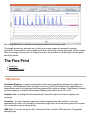
Energy Management Data
If your unit is equipped with an intelligent Energy Management System, detailed information about
energy usage and generation is available from a link in the CMS Information section of the screen
for that unit. The nine available graphs are explained here.
The graphs represent data gathered over a time period, 14 days by default. You can select a
different time period with the dropdown menu at the top right of the window.
Dashboard
Battery Voltage
Solar Voltage
Combined Voltage
Energy Generation
Energy Usage
Combined Energy
Energy Averages
Net Energy Generation
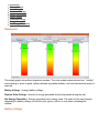
Dashboard
This simple graph shows three important numbers. The colorcoded scales indicate how ``healthy''
each reading is: green is good, yellow indicates a possible problem, and red indicates that action is
required.
Battery Voltage Average battery voltage.
Daytime Solar Voltage Amount of energy generated by the solar panels during the day.
Net Energy Generation Energy generated minus energy used. The scale for this one changes
depending on battery voltage, so use the color (green, yellow, or red) when evaluating this
number.
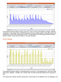
Battery Voltage
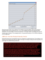
This graph shows the battery voltage over time. The line rises as the battery charges, and falls
during use. In the graph above, the lefthand side shows a healthy pattern, rising during the day
and falling at night, with no downward trend. The righthand end of the graph shows declining
battery voltage, a sign that the battery is not being charged.
Solar Voltage
This graph shows the voltage in the solar panels, over time. In the graph above, the 5th and 8th
days show a healthy ``batman cowl'' double peak; this shows that the batteries are charging all
day.
The triple peaks indicate that the equipment is functioning, but the batteries are not charging in the
middle of the day (in this case, because the batteries are full and the sign is using very little
power).
Nights, of course, show zero voltage.
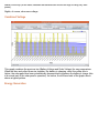
Combined Voltage
This graph combines the previous two (Battery Voltage and Solar Voltage) for easy comparison.
When the blue and yellow lines rise together, the battery is charging; when the yellow line is
higher, the solar panel has been automatically disconnected to preserve the battery's charge (this
is a normal part of the solar panel's operation). As before, the lefthand side of the graph above
shows a typical pattern.
Energy Generation
This graph shows the energy being generated by the solar panel that is used to charge the battery.
The first four days shown in the example have a double peak, typical of sunny days; the fifth shows
a typical cloudy day.
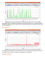
Energy Usage
This graph shows energy that is being used by the sign. In this example, energy usage is low, such
as when the screen is blank or showing a message that uses little power.
Combined Energy
This graph combines the previous two (Energy Generation and Energy Usage) for easy
comparison. The example shown here is typical of a low energy usage situation, such as a blank
screen.
Energy Averages
This graph shows a rolling average, each data point representing an average of the previous 24
hours. This makes for a smoother line than the Combined Energy graph. As above, green shows
energy generation and red shows energy usage.
Net Energy Generation
Net energy generation is defined as energy generated minus energy used.
This graph provides an alternate way of looking at energy usage as compared to energy
generation. Green sections of the graph show when net energy is being generated, and red shows
when net energy is being used. In a typical scenario, the amounts of red and green on the graph
should be similar.
The Fine Print
Definitions
License Agreement
Definitions
Automatic Blanking a powersaving feature that inserts short blanks between the pages of a
message. The blanks are all less than one second long (300750 milliseconds), depending on
battery status and on the batterys health as measured by nighttime voltage. If the battery is healthy
and near capacity, no blanks will be added. Blanking can also be set to On or Off.
Adaptive Text a setting that will automatically choose the right size of font to display your
message.
Animation a series of graphic pages that will be displayed one after another, to give the
appearance of motion. For example, an animation might show an arrow moving across the screen,
or a construction worker waving a flag.
CMS Unit Your sign, the device that Command Center controls. CMS stands for Changeable
Message Sign.
Communications Password Authorization to connect to the CMS unit via Control Center
3000©. If this password is blank, or the unit has never been communicated with, no password is
required to connect.
DataDriven Event see Event.
Default Message the message that is displayed when no schedules or events are in effect. If a
schedule is in effect, the Default Message will be displayed as soon as the schedule ends.
Dynamic Data data received from equipment attached to the CMS unit. Temperature, battery
voltage, and radar gun readings are examples of dynamic data.
Energy Management System On a CMS unit, the part that connects to the battery, solar panels,
etc. The on/off switch is located here.
Event or EventBased Schedule Displays a predetermined message, instead of the Default
Message, when certain conditions are met. For example, the Low Battery Warning Event is
activated when the battery voltage is low.
Font Letters of a certain size and appearance. For example, a 12pixel font is larger than a 9
pixel font. The Adaptive Text setting chooses a font size for you.
Font Set A group of fonts that are available to you. For example, a French font set may have
fonts with accented letters available, while the US DOT font set includes only fonts that have been
approved for use on US highways.
Graphic a message page that contains a picture.
IPAddressable refers to a CMS unit that can be assigned an IP address. This includes all units
except those that are equipped with a dialup modem.
Library a collection of messages. Libraries are stored on CMS units or on your local computer.
Read about libraries.
Local Libraries libraries that are stored on your computer (rather than on a CMS unit). If you
store messages in your local library, you can easily transfer them to one or more CMS units. The
Messages tab allows you to see and work with all available libraries.
Message a series of pages (text, graphics, or both) that can be displayed on the CMS unit. See
page to learn how to create a message.
Module a block of LEDs making up part of a sign panel.
Override Message A message, usually temporary, that is displayed instead of the normally
scheduled message. Use the Clear Override Message button to return to the scheduled message.
Page a component of a message. A page is the text or graphic that is displayed on the sign panel
for a period of time.
Pixel a dot making up part of a letter, number, picture, etc. Pixels may be on (lit LEDs) or off
(dark).
Quick Picks up to six messages that are available from the Quick Picks button on the CMS unit.
Runtime Total number of hours the unit has been in operation. This timer can be reset at any
time, like the trip odometer on a car. Not to be confused with Uptime, the time since the unit was
last rebooted.
Schedule A schedule specifies that a certain message will be displayed at certain times, instead
of the Default Message. A Onetime Schedule has a start time and end time; after the end time,
that schedule will not be displayed again. A Repeating Schedule also has a start and end time,
but can be repeated, for example every weekday or on a certain day of the month. If you need to
display a temporary message while a schedule is in effect, see Override Message.
TouchTone Control a way of interacting with your CMS unit by telephone. This feature is
available for any IPaddressable unit by calling +1 866 439 4522 and entering your Message
Board Number.
Working Library the main library of messages on your CMS unit.
Reference Library an additional library that typically contains graphics and other useful
messages. To use these messages, you will need to move them to the Working library.
TRAFIX© The software running inside your CMS unit.
Uptime Time since the unit was last rebooted. Uptime cannot be reset (but Runtime can).
License Agreement
SOLAR TECHNOLOGY, INC.
CONTROL CENTER 3000
SOFTWARE LICENSE AND LIMITED WARRANTY
PLEASE REVIEW THE FOLLOWING TERMS AND CONDITIONS CAREFULLY BEFORE USING THE SOFTWARE
PROVIDED ON THIS COMPACT DISK, WEBSITE, OR OTHER MEDIUM. BY USING THIS SOFTWARE YOU INDICATE
YOUR ACCEPTANCE OF SUCH TERMS AND CONDITIONS, WHICH CONSTITUTE THE LICENSE AGREEMENT (the
``Agreement'') BETWEEN YOU (the ``Licensee'') AND SOLAR TECHNOLOGY, INC. (``SolarTech''). IN THE EVENT THAT
YOU DO NOT AGREE WITH ANY OF THESE TERMS AND CONDITIONS, DO NOT DOWNLOAD, COPY, OR USE THIS
SOFTWARE; IF YOU HAVE RECEIVED A COPY ON COMPACT DISK OR ANOTHER MEDIUM, PLEASE PROMPTLY
RETURN THE SOFTWARE UNUSED TO SOLAR TECHNOLOGY, INC.
1. GRANT OF LICENSE
SolarTech, as Licensor, grants to you, the LICENSEE, a nonexclusive and nontransferable license to use this SOFTWARE
on a single COMPUTER at a single location so long as you comply with the terms of this License. Each workstation upon
which the SOFTWARE is used, whether such workstation is a standalone computer, networked computer or a terminal on
a multiuser computer must have a separately licensed copy of the SOFTWARE. SolarTech grants no other rights in the
SOFTWARE or documentation and retains the right to terminate this Agreement at any time should you violate any of its
terms.
2. GRANT OF SITE AND CORPORATE LICENSE
If you acquired a SITE LICENSE or a CORPORATE LICENSE, SolarTech grants to you the right to use the number of
copies of the SOFTWARE for which you have paid. For singleuser computers attached to a network (``Network
Workstations''), the quantity of the SOFTWARE in use is considered to be the maximum number of Network Workstations
on which the SOFTWARE is either loaded in memory or virtual memory or stored on a hard disk or other storage device at
the same time. For a multiuser computer, a use is counted for each occurrence of the SOFTWARE running on the
computer. If the anticipated number of users of the SOFTWARE can exceed the number of applicable licenses for which
you have paid, you must have a process in force to assure that the number of concurrent users of the SOFTWARE does
not exceed the number of licenses.
3. OWNERSHIP OF SOFTWARE
SolarTech retains exclusive copyright, title and ownership of the SOFTWARE and any associated written materials and any
subsequent or derivative copies of either regardless of their form. You may make one (1) copy of the SOFTWARE solely for
backup purposes. You must reproduce and include the copyright notice on the backup copy. SolarTech's ownership and
rights are protected by United States patent, copyright laws, and international treaty provisions. SolarTech is not aware of
any patent, copyright or other rights which may be infringed upon by your use of the SOFTWARE or documentation.
4. TRANSFERS
You may physically transfer the SOFTWARE from one computer to another provided that the SOFTWARE is used on only
one (1) computer at a time. You may not transfer, assign, lend, rent, lease, license, sublicense, sell, distribute or otherwise
dispose of the SOFTWARE or the documentation or the right to use the SOFTWARE or documentation to any other party
without the prior written consent of SolarTech. The individual files that are created during the execution of the installation
process or during normal operation of the SOFTWARE may not be distributed separately in any way.
5. USE RESTRICTIONS
You may not adapt, modify, decompile, disassemble, reverse engineer, translate or otherwise create any derivative works
based upon the SOFTWARE or the documentation. However, if you are located in a member nation of the European
Community or other nation that permits limited reverse engineering, you may perform reverse engineering, but only after
giving notice to SolarTech and only to the extent permitted by the European Community Software Directive or other
applicable law.
6. TERMINATION
This license is effective until terminated. This License is granted to you on the express condition that you will only use the
SOFTWARE and documentation in accordance with the terms of this License Agreement. If you fail to comply with any
provision of this License, this License will terminate automatically without notice from SolarTech. Upon termination, you
may no longer use the SOFTWARE or documentation, and all copies of both must be destroyed or returned to SolarTech.
You must also return or destroy any and all modified or derivative copies.
7. U.S. GOVERNMENT RESTRICTED RIGHTS.
The SOFTWARE and any accompanying materials are provided with Restricted Rights. Use, duplication or disclosure by
the Government is subject to restrictions as set forth in subparagraph (c)(1)(ii) of The Rights in Technical Data and
Computer Software clause at DFARS 252.2277013 or subparagraphs (c)(1) and (2) of the Commercial Computer Software
Restricted Rights at 48 CFR 52.22719, as applicable. Manufacturer is Solar Technology Inc., 7620 Cetronia Road,
Allentown, Pennsylvania, 18106 and its licensors.
8. LIMITED WARRANTY
SolarTech warrants the media on which the SOFTWARE is furnished to be free of defects in material and workmanship,
under normal use, for a period of ninety (90) days following the date of delivery to you. In the event of defects, SolarTech's
sole liability shall be to replace distribution media shown to be defective which is returned to SolarTech or the supplier with
your dated invoice. Any replacements will be warranted for the remainder of the original warranty period. In the event that
SolarTech is unable to replace defective media, SolarTech shall refund your purchase price upon your termination of this
license. THIS WARRANTY SHALL NOT APPLY TO ANY FAILURE OR NONCONFORMITY IN THE SOFTWARE
RESULTING FROM ACCIDENT, MISUSE OR MISAPPLICATION.
9. DISCLAIMER OF WARRANTIES
THE LIMITED WARRANTY, WHICH APPEARS ABOVE, IS IN LIEU OF ALL OTHER WARRANTIES, EXPRESS OR
IMPLIED, INCLUDING, BUT NOT LIMITED TO, ANY IMPLIED WARRANTY OF MERCHANTABILITY OR FITNESS FOR
A PARTICULAR PURPOSE. SolarTech DISCLAIMS WITHOUT LIMITATION ALL OTHER WARRANTIES. THE
SOFTWARE AND DOCUMENTATION ARE PROVIDED ``AS IS'' WITHOUT ANY OTHER WARRANTY CONCERNING
THE USE, OR THE RESULTS OF USE, OF THE SOFTWARE OR THE DOCUMENTATION, AND WITHOUT ANY
WARRANTY THAT THE FUNCTIONS CONTAINED IN THE SOFTWARE WILL MEET YOUR REQUIREMENTS OR THAT
THE OPERATION OF THE SOFTWARE WILL BE UNINTERRUPTED OR ERROR FREE.
10. NO OTHER WARRANTIES
YOU AGREE THAT NO ORAL OR WRITTEN REPRESENTATION, DEMONSTRATION, STATEMENTS, ADVICE OR
ADVERTISEMENTS BY SolarTech, ITS AGENTS, DEALERS, DISTRIBUTORS OR EMPLOYEES CONSTITUTES ANY
WARRANTY OR MODIFICATION OF THIS STATED DISCLAIMER AND LIMITED WARRANTY.
11. NO LIABILITY FOR CONSEQUENTIAL DAMAGES
NEITHER SolarTech NOR ANY OTHER PERSON OR ENTITY INVOLVED IN THE DEVELOPMENT, PRODUCTION,
MARKETING OR DELIVERY OF THE SOFTWARE SHALL BE LIABLE FOR ANY DIRECT, INDIRECT,
CONSEQUENTIAL, INCIDENTAL OR SPECIAL DAMAGES (INCLUDING DAMAGES FOR LOSS OF BUSINESS
PROFITS, BUSINESS INTERRUPTION, LOSS OF BUSINESS INFORMATION, INFRINGEMENTS OF PATENT,
COPYRIGHT, TRADE SECRET OR OTHER INTELLECTUAL PROPERTY RIGHTS, OR FAILURE TO REALIZE
SAVINGS) OR LIKE DAMAGES, REGARDLESS OF THE LEGAL BASIS FOR SUCH LIABILITY, RELATED TO THE USE
OR THE INABILITY TO USE THE SOFTWARE OR DOCUMENTATION, EVEN IF SolarTech HAS BEEN ADVISED OF
THE POSSIBILITY OF SUCH DAMAGES, AND EVEN IF THE CUSTOMER REMEDY IDENTIFIED IN THIS AGREEMENT
IS DEEMED TO HAVE FAILED OF ITS ESSENTIAL PURPOSE. BECAUSE SOME STATES DO NOT ALLOW THE
EXCLUSION OR LIMITATION OF LIABILITY FOR CONSEQUENTIAL OR INCIDENTAL DAMAGES, THE ABOVE
LIMITATION MAY NOT APPLY TO YOU.
12. LIMITATION OF LIABILITY
Should any other warranties be found to exist, such warranties shall be limited in duration to ninety (90) days following the
date of delivery to you. In no event will SolarTech's liability for any damages to you or any other person exceed the amount
paid for the license to use the SOFTWARE.
13. LEGAL DOMAIN
This Agreement is entered into for the benefit of SolarTech and its licensors and all rights granted to you and all obligations
owed to SolarTech shall be enforceable by SolarTech and its licensors. If you have any questions concerning this
Agreement, including software maintenance or warranty service, you should contact Solar Technology, Inc., 7620 Cetronia
Road, Allentown, PA, 18106. This Agreement shall be governed and construed by the laws of the Commonwealth of
Pennsylvania. You agree to submit to the jurisdiction of the courts in the Commonwealth of Pennsylvania for the resolution
of any dispute or claim arising out of or relating to this Agreement. The prevailing party in any legal action or arbitration
arising out of this Agreement shall be entitled to reimbursement for its expenses, including court costs and reasonable
attorneys' fees, in addition to any other rights and remedies such party may have.
BY USING THE LICENSED PROGRAM(S) YOU ACKNOWLEDGE THAT YOU HAVE READ THIS AGREEMENT,
UNDERSTAND IT, AND AGREE TO BE BOUND BY ITS TERMS AND CONDITIONS. YOU FURTHER AGREE THAT IT
IS THE COMPLETE AND EXCLUSIVE STATEMENT OF THE AGREEMENT BETWEEN YOU AND SOLAR
TECHNOLOGY, INC. WHICH SUPERSEDES ANY PROPOSAL OR PRIOR AGREEMENT, ORAL OR WRITTEN, AND
ANY OTHER COMMUNICATIONS BETWEEN YOU AND SOLAR TECHNOLOGY, INC. RELATING TO THE SUBJECT
MATTER OF THIS AGREEMENT. Command Center User's Guide. © 2014 Solar Technology, Inc.
Need to talk to Tech Support? Call 6103918600 or visit the Solar Technology website.